

Page 1
LORD QUICKSTARTGUIDE
V-Link®-200
Wireless 8 Channel Analog Input Sensor Node
The V- Link - 200 wireless sensor node features eight analog input channels
designed to accommodate a wide range of Whea tstone bridge and analog
sensors, including strain, load cell, torque, pressure, acceleration, vibration,
magnetic field, displacement, and geophones. There are four channels for singleended sensor measurement, four channels for differential sensor measurement,
and an on-board internal temperature sensor.
To acquire sensor data, the V- L ink- 200 is used with a LORD Sensing data
gateway such as the WSDA-101 or WSDA-1500 Base. V-Link-200 sensor nodes
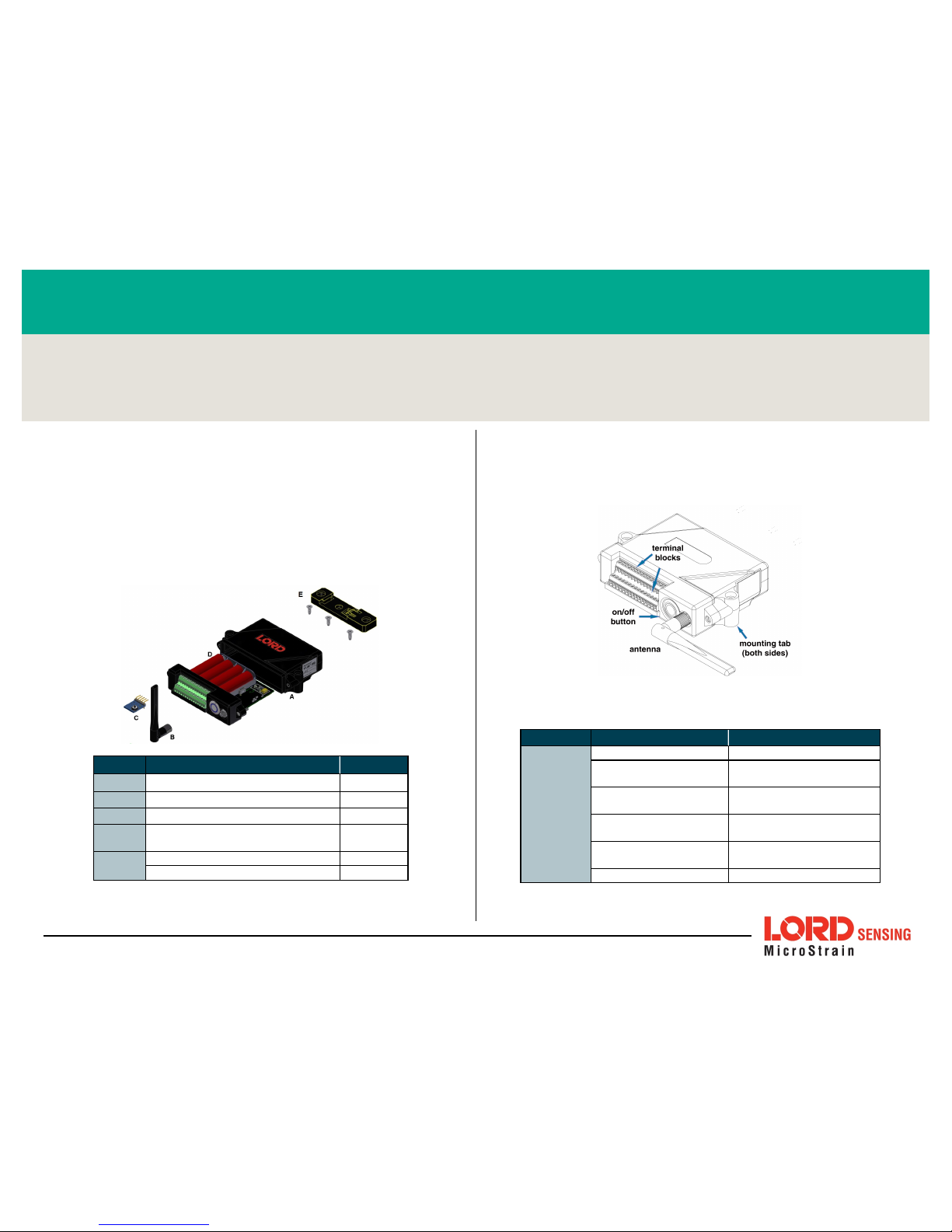
come with the following components.
Item Desc ri ption Quantity
A
V-Link-200 1
B
Antenna with right angle adapter 1
C
Node tester board 1
D
AA Lithium batteries (3.6 V dc, 2.4
Ah)
4
E
DIN rail clip 1
#6-32 x 3/8" Thread forming screws 3
The V-Link-200 LEDs indicate operational modes showing when the node
is booting up, idle and waiting for a command , sampling, resynchronizing,
or if the re is an error.
Figure 1 - Interf ace and Indicators
Indicator Behavior Node Status
Device
status
indicator
OFF Node is OFF
Rapid green flashing
on start-up
Node is boo ting up
1 (slow) green pulse
per second
Node is idle and waiting
for a command
1 green blink every 2
seconds
Node is sampling
Blue LED during
sampling
Node is resynch ronizing
Red LED Error or low battery
Wireless Simplicit y, Hardwired Reliab ilit y™
Page 2
SYSTEM OPERATION
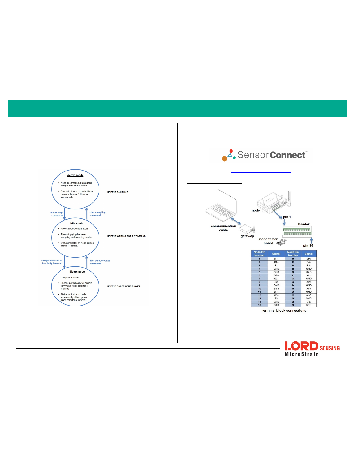
Sensor no des have three ope rational modes:
active,sleep
, and
idle
. When the
node is sampling, it is in active mode. When sampling stops, the node is switched
into idle mode, which is used for configuring node settings, and allows toggling
between sampling and sleeping modes. The node will automatically go into the
ultra low- power slee p mode after a user- determined period of inactivity. The
node will not go into sleep mode while sa mpling.
Figure 2 - Node Operat ional Modes
1. I nstall So ftware
Install the SensorCo nnect software on the host computer before connecting any
hardware. Access the free software download on the LORD Sensing w ebsite at:
http://www.microstr ain.c om/software
2. Make System Connect ions
2
V-Link®-20 0 Wireless Sensor Node QuickStar t Guide
Page 3

3. Est ablish G ateway Communication
Drivers for the USB gateways are included the SensorConnect software
installa tion. With the software installed, the USB gateway will be detected
automatically whenever the gateway is plugged in.
1. Power is applied to the gateway through the USB connection. Verify
the gatewa y status indicator is illuminated, showing the gateway is
connected and powered on.
2. Open the Se nsorConnect software.
3. The gateway should appear in the Controller window au tomatically
with a communication port assignment. If the gateway is not
automatically discovered, verify the port is active on the ho st
computer, and the n remo ve and re-insert the USB connector.
Figure 3 - USB G ateway Communication
4. Connect t o Nodes
Several methods can be used in Sen sorConnect to establish communication with
the nodes: the automatic node discovery feature, manually entering the node
address, and scanning transmission frequency and node address ra nges.
A. Add Node Via Node Discovery
If the base and node are on the same operating frequency, the node will
populate below the Base Station listing when powering on the V-Link-200.
Figure 4 - Node Disco vered On Same Frequency
If a red circle with a number a ppears next to the Base Station, the node is
operating on a separate radio channel (see Connect to Nodes on page 3.).
Figure 5 - Node On Other Frequency
3
V-Link®-20 0 Wireless Sensor Node QuickStar t Guide
Page 4
B. Add Node Manually
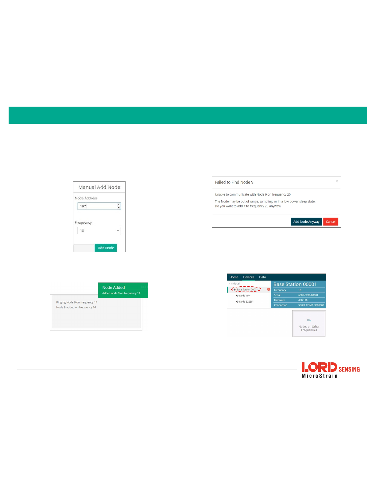
Adding a node manually requires entering the node address and its
current frequency setting.
From the Base Station, select the Manual Add Node tile, enter the Node
Address, last known Frequency (factory default is 15), and select Add
Node.
Figure 6 - Add Node By Address
If the node was successfully added, two confirmation messages will
appear and it will be listed under the Base Station.
Figure 7 - Add Node Confirmation
If the node failed to be added, a failure message will appear. This means
the node did not respond to the base station which could indicate the
node is not in idle mode or it may be on another frequency. If "Add Node
Anyway" is selected, it will associate that node with the channel entered
but it is likely there will be a communication error. If the node was not in
idle, move the base station to the frequency of the node and issue a "Set
to Idle" command.
Figure 8 - Failure to Add Node
C. Move Node t o Base Station F requency
If a red circle with a number appears next to Base Station, the node is
operating on a separate radio chann el. Select the Base Station and then
select the Nodes on Other Freq uencies tile.
Figure 9 - Nodes On Other Frequencies
4
V-Link®-20 0 Wireless Sensor Node QuickStar t Guide
Page 5
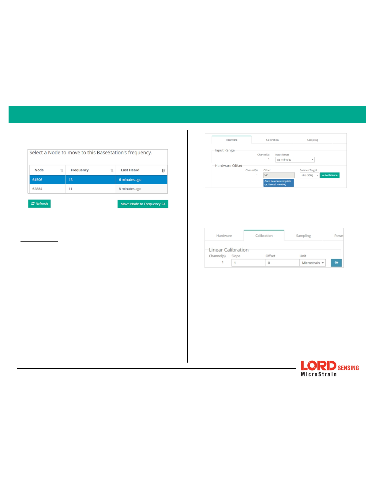
Highlight the new node being added and select Move N ode to Frequency
(#).
Figure 10 - Move No de
5. Configure Node
Node settings are stored to non- volatile memory and may be configured using
SensorConnect. The configuration menus show the channels and configuration
options available for the type of node being used.
For this e xample the V-Lin k-200 tester board is on channel 1.
1. Select Hardware > Input Range for channel 1, select +/-2 mV from
the drop down me nu.
2. Under Hardware Offset, select Balance Target for channel 1, select
Mid (50%) from the drop down menu.
3. Select Auto- Balance. When auto- balance is complete, a blue
information window will indicate the balance result.
Figure 11 - Auto-Balance
4. Select Calibration.
5. Select Microstrainfrom the Unit drop do wn menu , and select the
Shunt Cal button enabled on the right.
Figure 12 - Node Configurat ion Menu
6. Use the following settings:
a. Calibration Mode: Internal
b. Number of Active Gauges: 4
c. Gauge F actor: 2
d. Gauge Resistance: 1000
e. Shunt Resist ance: 499000
7. Select Start Shunt Cal for Slope and Offset calibrations.
8. Select Accept Calibration.
5
V-Link®-20 0 Wireless Sensor Node QuickStar t Guide
Page 6
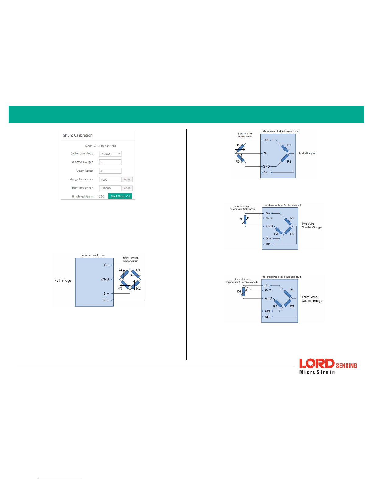
Figure 13 - Channel Settings
9. When the calibration is complete, the Wireless Nod e Configuration
window will a ppear.
10. Select Apply Configuration to write to node memory.
See below for wiring of other strain gauges.
Figure 14 - F ull-Bridge (Standard)
Figure 15 - Half-Bridge *
Figure 16 - T wo Wire Quarter-Bridge *
Figure 17 - T hree Wire Quart er-Bridg e *
* Requires optional on-board bridge completion
6
V-Link®-20 0 Wireless Sensor Node QuickStar t Guide
Page 7
6. Configure Sampling Sett ing and St art Data Acquisit ion
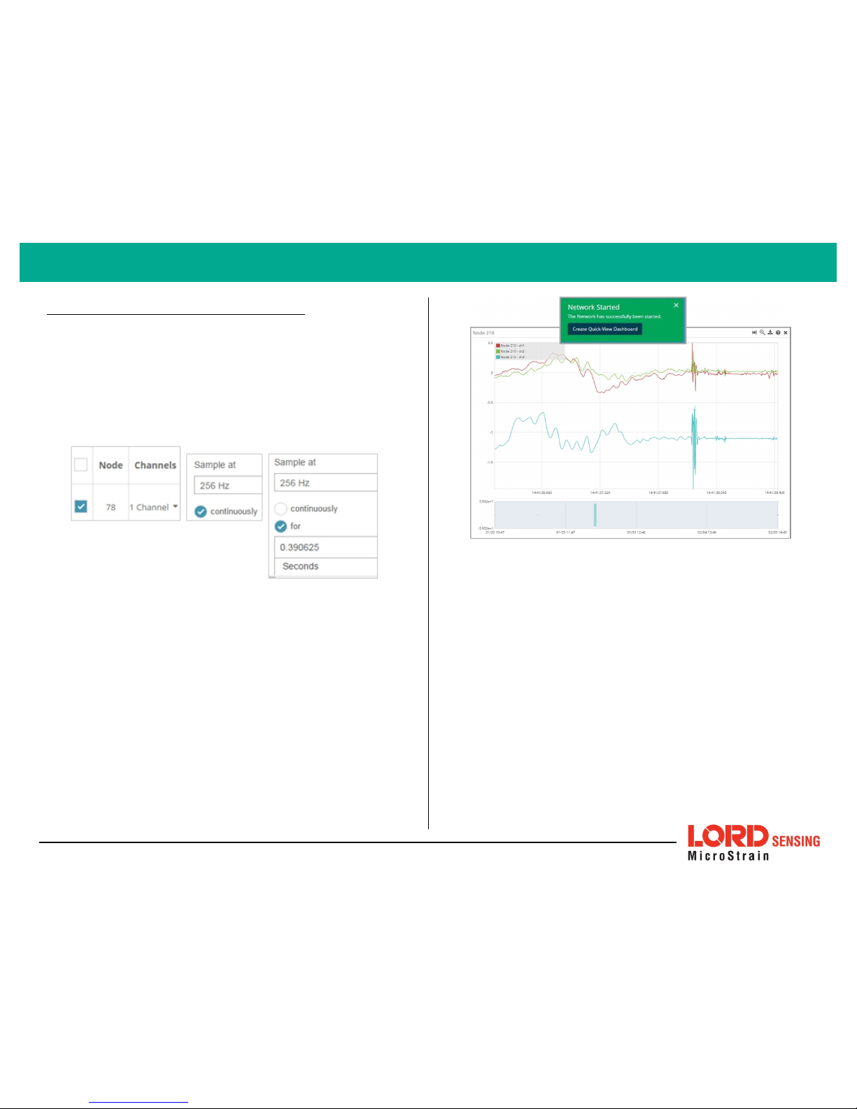
1. Left click on the Base Station > Sa mpling, and indicate the nodes to be
sampled by checking the box to the left of each node.
2. Under 3 Channels, select Raw Channels, ch1, ch2 and ch3 from the
drop down menu.
3. Under Sampling, select Sample Rate from the drop down menu, select
Continuously to sample indefinitely, or For to set a limited time for
sample sets.
Figure 18 - Sampling Set tin g
4. Select Apply and Start Network.
5. Select Create QuickView Dashboard in the pop up window immediately
to create a dashboard of the new data.
Figure 19 - Q uick View Da shboard
7
V-Link®-20 0 Wireless Sensor Node QuickStar t Guide
Page 8

V-Link®-20 0 Wireless Sensor Node QuickStart Guide
7. Replacing Batteries
1. Remove the screws on both sides of the face plate to open the V-Link-
200.
2. It is importan t to replace all four of t he batteries at t he same time,
observing the correct polarity orientation. The positive polarities are
indicated on the batteries and the node by a "+" symbol.
3. Reassemble.
Figure 20 - Replace Bat teries
8. Battery Hazards
The V- Link - 200 contains internal, non- rechargeable
lithium batteries . Lithium batteries are a fire and
explosion hazard. Do not store or operate the node at
temperatures above 212°F (100°C). Do not
disassemble, short circuit, crush, puncture, o r otherwise
misuse the battery.
Lithium b atteries contain toxic chemicals that are
harmful to humans and the environment. Disposal is
subject to federal a nd local laws. Do not discard the
battery or the node in the trash. Follow proper battery
disposal protocol, or contact LORD Sensing Technical
Support for information on extracting the battery or
returning the product for proper recycling and disposal.
9. Power Supply
Apply only the input voltage range specified for the VLink-200 . Connect to a p ower source that is near the
device, is accessible, and adheres to all n ational wiring
standards. Compliance with wiring standards is
assumed in the installation of the power source an d
includes pro tection against excessive currents, short
circuits, and ground faults. Failure to do so could result
in personal injury and permanent damage to the
device.
LORDCo rpo ratio n
Micro Strain®Sensin g Systems
459Hurri caneLane, Suite 102
Willi ston, VT 05495USA
ph: 802-862-6629
Copyright© 2017LORD Corporation
Document 8501-0073Revision G. Subjectto changewithoutnotice.
www.microstrain.com
 Loading...