

Page 1
LORD QUICKSTARTGUIDE
G-Link®-200-OEM
High-Speed Triaxial Accelerometer Node
The G-Link-200-OEM wireless accelerometer node features an on-board triaxial
accelerometer that allows high-resolution data acquisition at noise levels as low
as 25 or 80 µg√Hz.The G-Link-200-OEM can output continuous waveform data,
or one of four derived channels, including Velocity (IPS
G
) and Crest Factor, allowing long-term monitoring of key performance
pk- pk
indicators while maximizing battery life. To acquire sensor data, the G-Link-200OEM is used with a LORD Sensing WSDA gateway, and comes with the following
configuration options.
), Amplitude (G
rms
rms
and
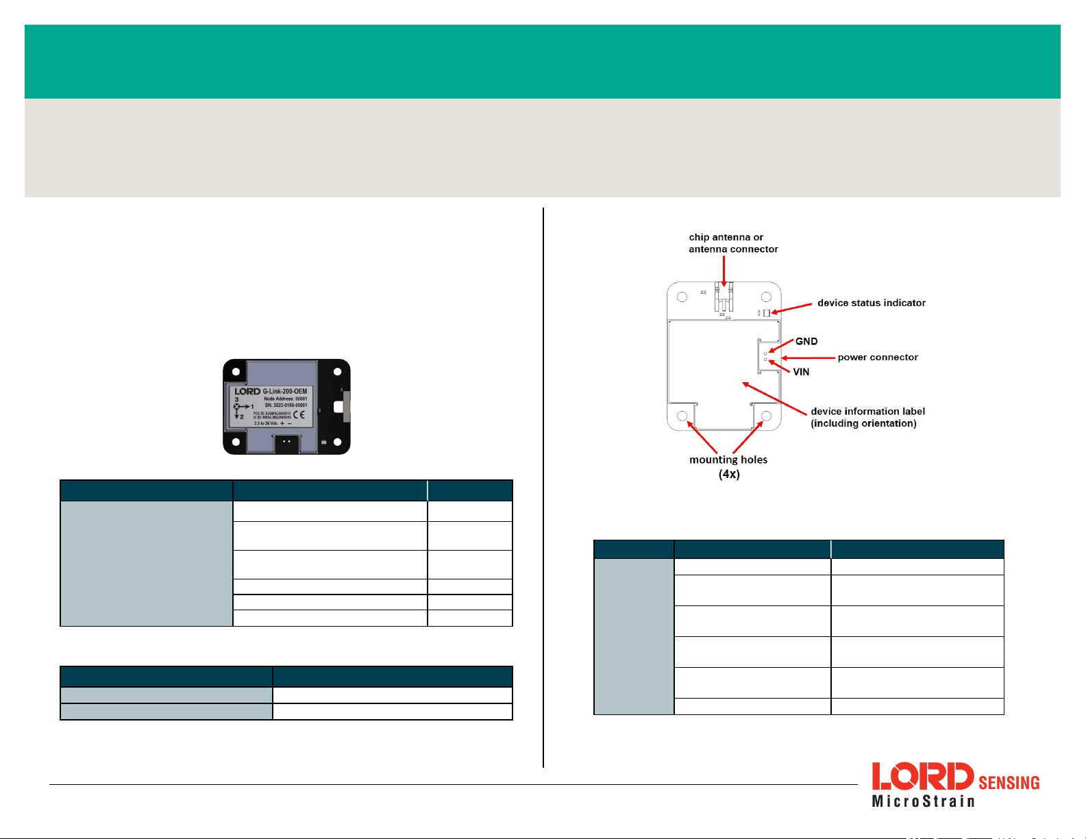
Configuration Option Antenna Gain
Integrated chip antenna 1.5 dBi
MMCX interface:IP67 rated whip
antenna, 1 m cable
G-Link-200 OEM PCB
Table 1 - G-Link-200-OEMConfiguration Options
Part Description
Power Interface Kit
Mounting Kit
Wireless Simplicity, Hardwired Reliability™
MMCX interface: Indoor rated whip
antenna, 12" cable
U.FL interface:Flag antenna, 4" cable 2.5 dBi
U.FL interface: Stub antenna, 2" cable -0.9 dBi
Calibration Certificate --
Power connector and matingcable
Mounting board, 4 screws
Table 2 - G-Link-200-OEM Parts
2.0 dBi
2.5 dBi
Figure 1 - Interface and Indicators
Indicator Behavior Node Status
OFF Node is OFF
Device
status
indicator
Rapid green flashing
on start-up
1 (slow) green pulse
per second
1 green blink every 2
seconds
Blue LED during
sampling
Red LED Built-in test error
Table 3 - Indicator Behaviors
Node is booting up
Node is idle and waiting
for a command
Node is sampling
Node is resynchronizing
Page 2
G-Link®-200-OEM Wireless Accelerometer Node QuickStart Guide
SYSTEM OPERATION
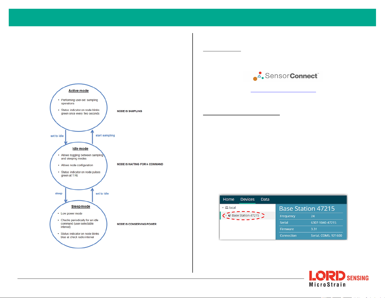
Sensor nodes have three operational modes:
node is sampling, it is in active mode. When sampling stops, the node is switched
into idle mode, which is used for configuring node settings, and allows toggling
between sampling and sleeping modes. The node will automatically go into the
ultra low- power sleep mode after a user- determined period of inactivity. The
node will not go into sleep mode while sampling.
active,sleep
, and
idle
. When the
1. Install Software
Install the SensorConnect software on the host computer before connecting any
hardware. Access the free software download on the LORD Sensing website at:
http://www.mic rostrain.com/software
2. Establish Gateway Communication
Drivers for the USB gateways are included the SensorConnect software
installation. With the software installed, the USB gateway will be detected
automatically whenever the gateway is plugged in.
1. Power is applied to the gateway through the USB connection. Verify
the gateway status indicator is illuminated, showing the gateway is
connected and powered on.
2. Open the SensorConnect™ software.
3. The gateway should appear in the Controller window automatically
with a communication port assignment. If the gateway is not
automatically discovered, verify the port is active on the host
computer, and then remove and re-insert the USB connector.
Figure 3 - USB Gateway Communication
Figure 2 - Node Operational Modes
2
Page 3
G-Link®-200-OEM Wireless Accelerometer Node QuickStart Guide
3. Connect to Nodes
Several methods can be used in SensorConnect to establish communication with
the nodes: the automatic node discovery on the same frequency, automatic node
discovery on a different frequency, and add node manually.
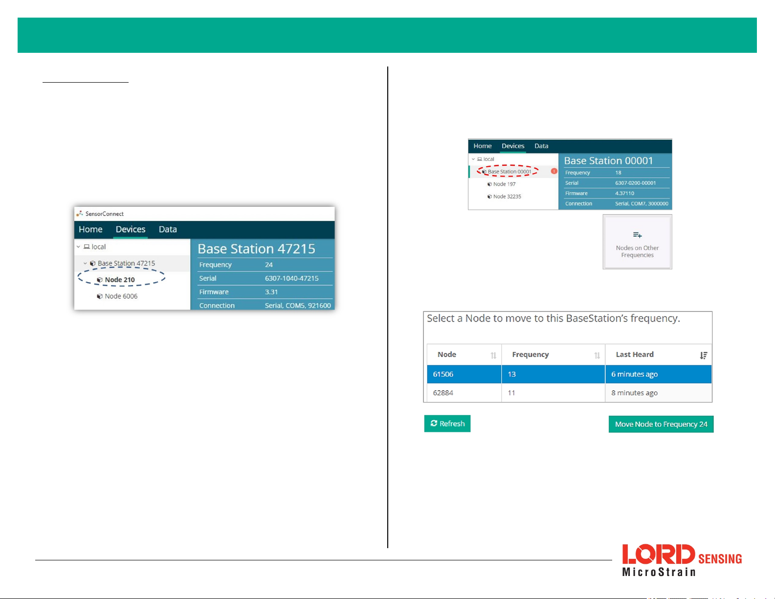
A. Automatic Node Discovery on Same Frequency
If the base and node are on the same operating frequency, the node will
populate below the Base Station listing when powering on the G-Link-200OEM.
B. Automatic Node Discovery on Different Frequency
If a red circle with a number appears next to the Base Station, the node is
operating on a separate radio channel. Select the Base Station and then
select the Nodes on Other Frequencies tile.
Highlight the new node being added and select Move Node to Frequency
(#).
3
Page 4
G-Link®-200-OEM Wireless Accelerometer Node QuickStart Guide
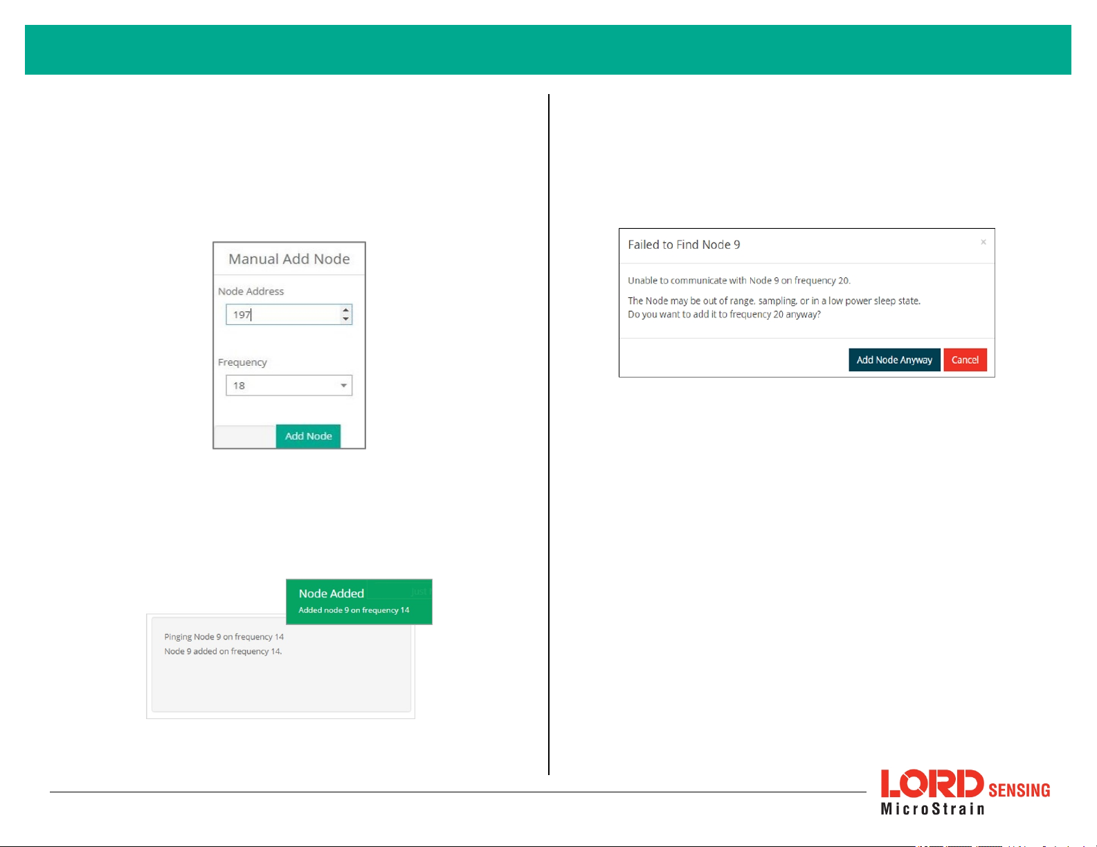
C. Manually Add Node
Adding a node manually requires entering the node address and its
current frequency setting.
From the Base Station, select the Manual Add Node tile, enter the Node
Address, last known Frequency (factory default is 15), and select Add
Node.
If the node failed to be added, a failure message will appear. This means
the node did not respond to the base station which could indicate the
node is not in idle mode or it may be on another frequency. If "Add Node
Anyway" is selected, it will associate that node with the channel entered
but it is likely there will be a communication error. If the node was not in
idle, move the base station to the frequency of the node and issue a "Set
to Idle" command.
If the node was successfully added, two confirmation messages will
appear and it will be listed under the Base Station.
4
Page 5
G-Link®-200-OEM Wireless Accelerometer Node QuickStart Guide
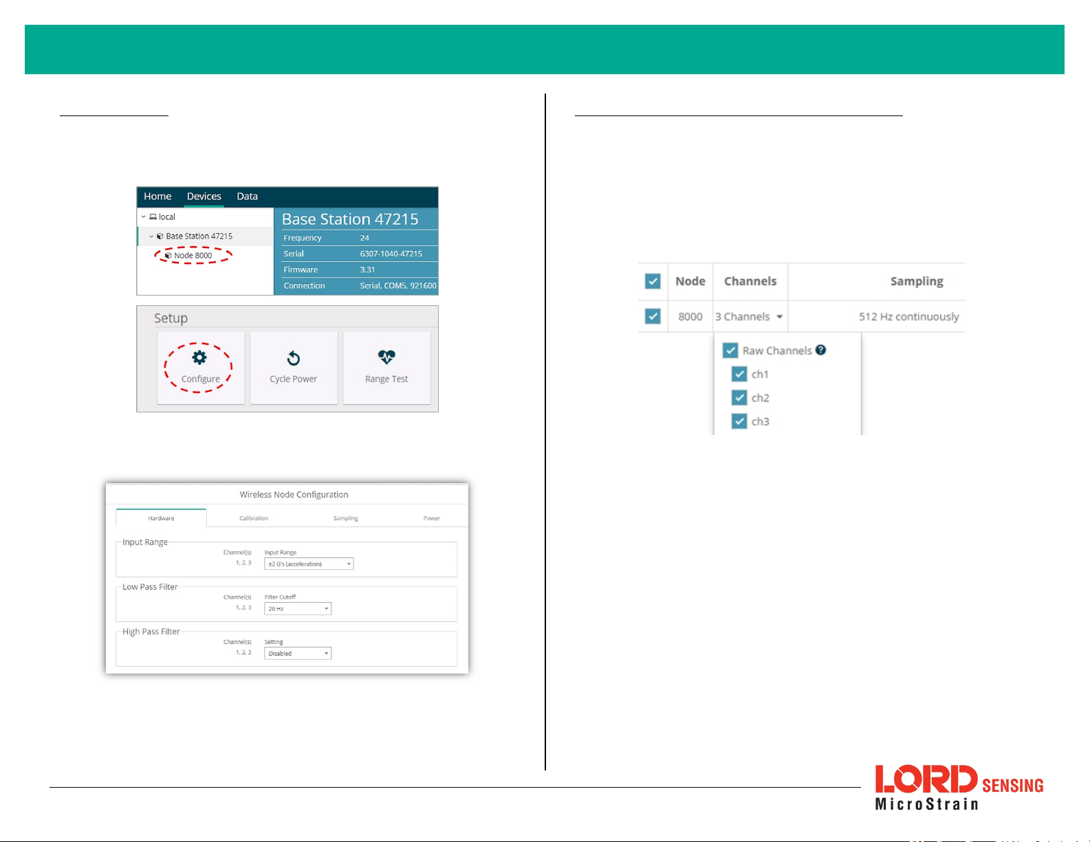
4. Configure Node
Node settings are stored to non-volatile memory and may be configured using
SensorConnect. To access the node configuration menu,under Devices select
the node and then the Configure tile.
The configuration menus show the channels and configuration options available
for the type of node being used.
5. Configure Sampling Setting and Start Data Acquisition
1. Left click on the Base Station > Sampling, and indicate the nodes to be
sampled by checking the box to the left of each node.
2. Under 3 Channels, select Raw Channels, ch1, ch2 and ch3 from the
drop down menu.
3. Under Sampling, select Sample Rate from the drop down menu, select
Continuously to sample indefinitely.
Figure 5 - Sampling Setting
4. Select Apply and Start Network.
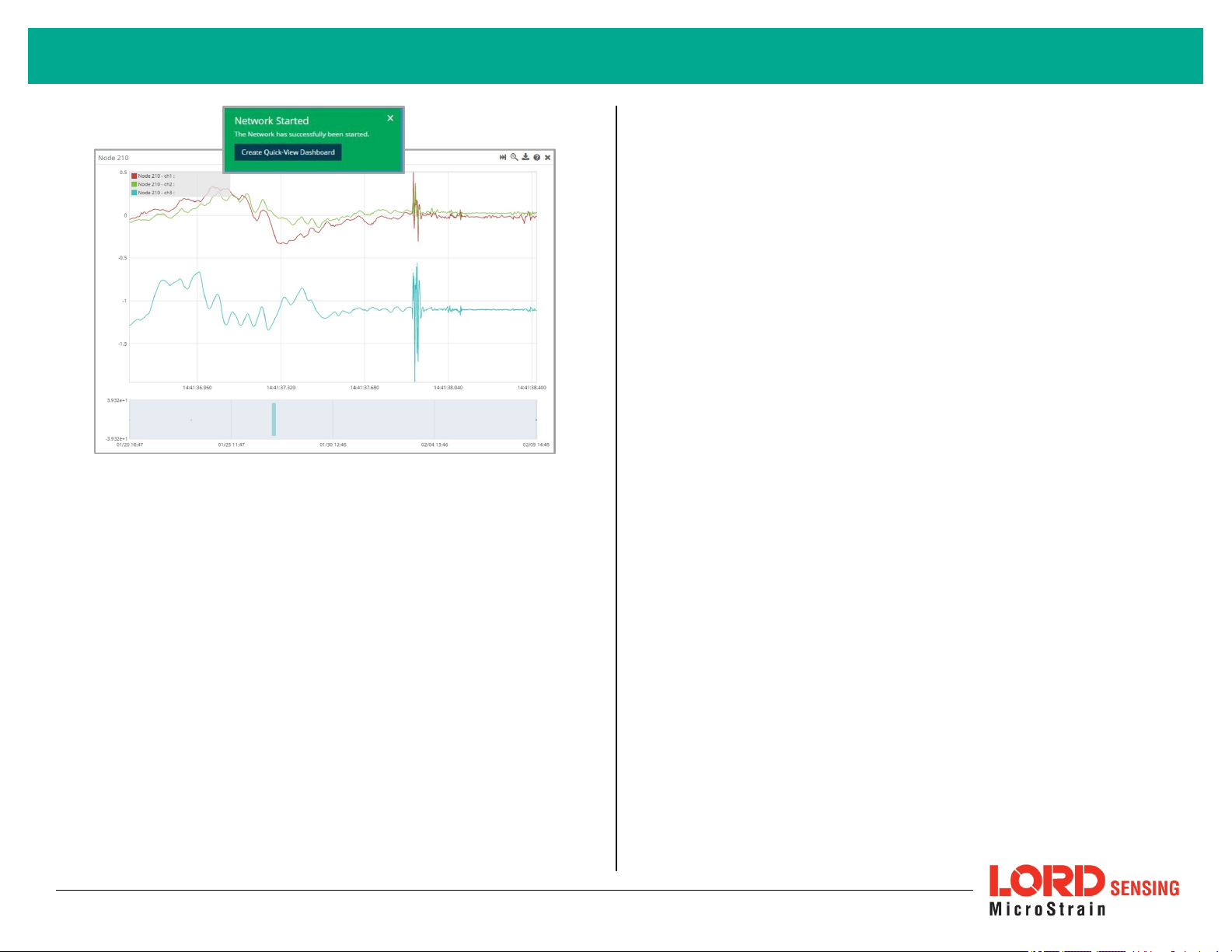
5. Select Create QuickView Dashboard in the pop up window immediately
to create a dashboard of the new data.
Figure 4 - Node Configuration
5
Page 6
G-Link®-200-OEM Wireless Accelerometer Node QuickStart Guide
Figure 6 - Quick View Dashboard
6
Page 7
G-Link®-200-OEM Wireless Accelerometer Node QuickStart Guide
Radio Specifications
The G- Link- 200- OEM employs a 2.4GHz IEEE 802.15.4- compliant radio
transceiver for wireless communication. The radio is a direct-sequence spread
spectrum radio and can be configured to operate on 16 separate frequencies
ranging from 2.405 GHz to 2.480 GHz. Following the 802.15.4 standard, these
frequencies are aliased as channels 11 through 26. For all newly manufactured
nodes, the default setting is 2.425 GHz (channel 15).
G-Link-200-OEM
FCC ID: XJQMSLINK0010
IC ID: 8505A-MSLINK0010
This device complies with Part 15 of the United States FCC Rules, and
Industry Canada’s license-exempt RSSs. Operation is subject to the
following two conditions: 1) This device may not cause interference, and
2) This device must accept any interference, including interference that
may cause undesired operation of the device. Changes or modifications,
including antenna changes not expressly approved by LORD
Corporation could void the user’s authority to operate the equipment.
Cet appareil est conforme à la Partie 15 des Règles de la FCC des
États-Unis et aux RSSS exempts de licence d'Industrie Canada. Le
fonctionnement est soumis aux deux conditions suivantes: 1) Cet
appareil ne doit pas causer d'interférences et 2) Cet appareil doit
accepter toute interférence, y compris les interférences pouvant
entraîner un fonctionnement indésirable de l'appareil. Les changements
ou modifications, y compris les changements d'antenne non
expressément approuvés par LORD Corporation, pourraient annuler
l'autorisation de l'utilisateur d'utiliser l'équipement.
ESD Sensitivity
The G-Link-200-OEM is intended to be integrated in to an application appropriate
housing to protect it from environmental elements, impact, and electrostatic
discharge (ESD), which can disrupt operation or damage the PCB.
The G-Link-200-OEM is susceptible
to damage and/or disruption of
normal operation from Electrostatic
Discharge (ESD). ESD may cause
the device to reset, which may
require user intervention to continue
data acquisition.
LORDCo rp oration
Micro Strain®Sensing System s
459 HurricaneLane , Suite 102
Williston, VT 05495 USA
ph: 802-862-6629
Copyright © 2018 LORD Corporation
Document 8501-0094RevisionA. Subject to change without notice.
www.microstrain.com
 Loading...