

Page 1

200 Series Radio Module Integration Guide
1. Overview
The 200 Series Radio Module is an OEM device used to acquire data from LORD Corporation wireless sensing
devices. It is designed to be embedded in other products to provide radio communication and data passthrough capabilities in a modular format. It is designed to be used with LORD data acquisition software or
user software developed using the LORD MSCL code library.
The module includes an integrated microcontroller/radio transceiver that communicates to LORD devices in
the 2.4 GHz band. There are two radio transmission protocols that are available on the radio module – the
standard 802.15.4 protocol (LXRS) and a LORD proprietary protocol (LXRS+). The modes are selectable in the
LORD software. Both are capable of lossless transmission of continuous, burst, and other sampling modes,
depending on sensor node capabilities.
2. Integration
The radio module requires a PCB carrier board for proper integration. This board can be designed by LORD,
or by an OEM customer with the information provided in this document. The carrier board provides power
(+5 Vdc +/- 2%, 50mA) to the radio module, as well as the serial and input/output interface to connect the
microcontroller to the larger communication system. The microcontroller code required to control the radio
module is proprietary and is developed at LORD.
The following section describes physical layout and pin configuration of the module. The module is 0.98” x
0.53”. It has either an internal antenna on one end of the board or an MMCX connecter used to interface
with specified external antennas and cables. The interface to the carrier board is through solder pads around
the three other sides of the board. For exact layout dimension of these pads, contact LORD Technical Support
for an engineering file.
The radio module is an OEM circuit board intended to be housed in an enclosure of the type suitable for the
final product. It has no environmental protection by itself. Operating temperature range is -40 to +85 °C.
LORD Corporation 1/15/2018 Revision A Prepared by J. Dunklee
Page 2
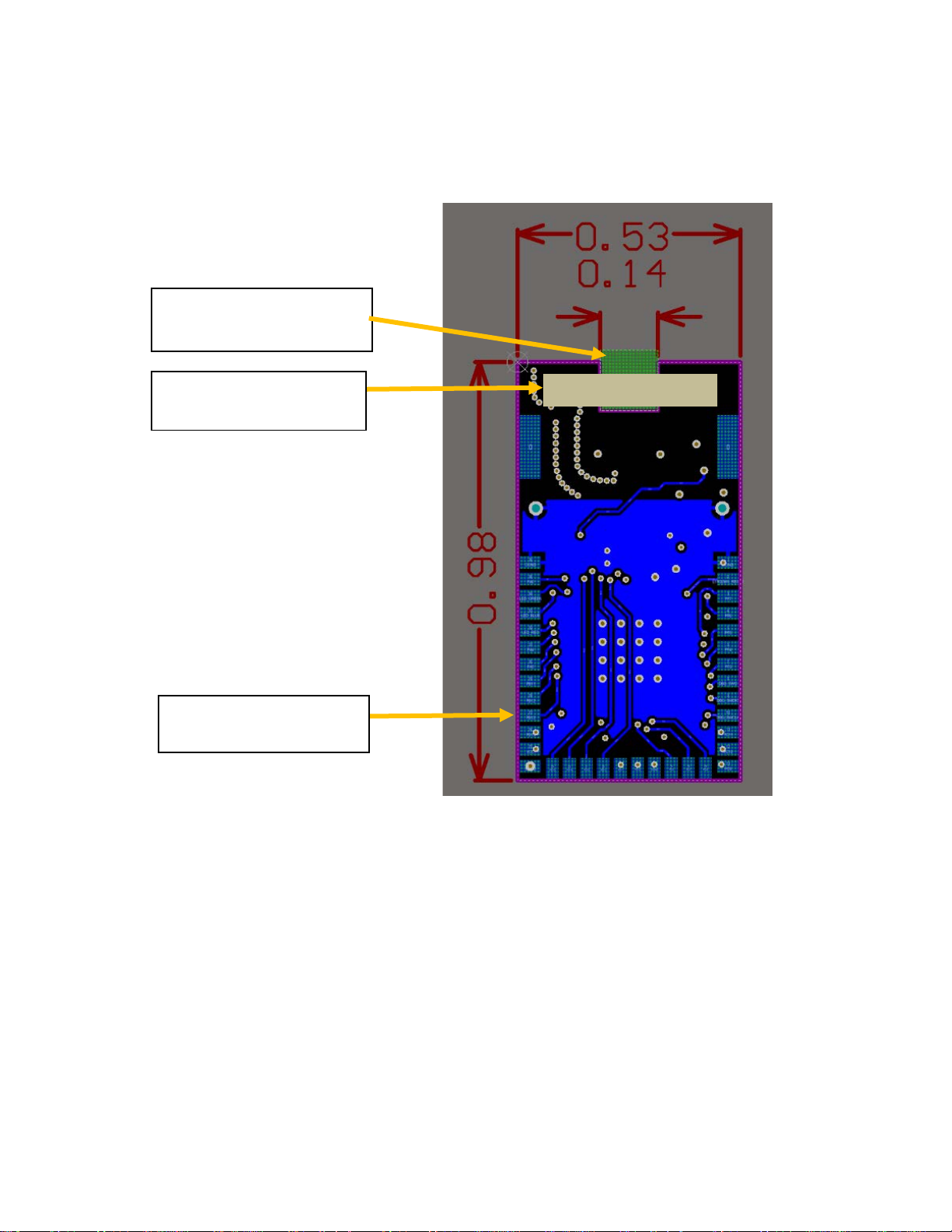
Dimensions in inches
Physical Interface
External antenna connector
location (if applicable)
Internal antenna location
(if applicable)
Carrier board solder pads
(around board edge)
LORD Corporation 1/15/2018 Revision A Prepared by J. Dunklee
Page 3

Pin Interface
Radio Module
Signal name
Description
1
DGND
Digital ground
2
EFR32MG RESET
Microcontroller reset
3
PF7
Microcontroller general purpose I/O
4
PF6
Microcontroller general purpose I/O
5
PF5
Microcontroller general purpose I/O
6
PF4
Microcontroller general purpose I/O
7
PF3
Microcontroller general purpose I/O
8
DBG_SWO
Serial Wire Debug trace data output
9
DBG_SWDIO
Serial Wire Debug data in/out
10
DBG_SWCLK
Serial Wire Debug clock
11
PC11
Microcontroller general purpose I/O
12
PC10
Microcontroller general purpose I/O
13
PC9
Microcontroller general purpose I/O
14
PC8
Microcontroller general purpose I/O
15
PC7
Microcontroller general purpose I/O
16
PC6
Microcontroller general purpose I/O
17
DGND
Digital ground
18
PD10
Microcontroller general purpose I/O
19
PD11
Microcontroller general purpose I/O
20
PD12
Microcontroller general purpose I/O
21
PD13
Microcontroller general purpose I/O
22
PD14
Microcontroller general purpose I/O
23
PD15
Microcontroller general purpose I/O
24
DGND
Digital ground
25
VCC
Module power input +5V dc
26
PB15
Microcontroller general purpose I/O
27
PB13
Microcontroller general purpose I/O
28
PB12
Microcontroller general purpose I/O
29
PB11
Microcontroller general purpose I/O
30
PA5
Microcontroller general purpose I/O
31
PA4
Microcontroller general purpose I/O
32
LED_RED
Status LED red
33
LED_BLUE
Status LED blue
34
LED_GREEN
Status LED green
35
PA0
Microcontroller general purpose I/O
36
DGND
Digital ground
pin number
LORD Corporation 1/15/2018 Revision A Prepared by J. Dunklee
Page 4
3. Approved Antennas and Cables
Model Description
Number
Option Description
Antenna Mfg PN
Gain
Integrated chip
JOHANSON
Laird Technologies
RPTNC standard antenna
L-COM HG2403RD-RTF
3.0 dBi
Linx Technologies
MMCX antenna
Data Alliance A9
1.5 dBi
LORD Model
antenna
External antenna 3022-0021 RPTNC outdoor rated antenna
RPSMA, standard antenna
3022-0017 (not applicable)
2450AT45A100E
001-0042
ANT-DB1-RAF-RPS
Antenna
1.5 dBi
2.0 dBi
2.5 dBi
Cables up to one meter in length are approved to connect these antennas to the 200 Series Radio Module.
Cables must be 50 ohm RF cable types, such as RG-178 and LMR-100, with applicable connectors.
4. Regulatory Marks
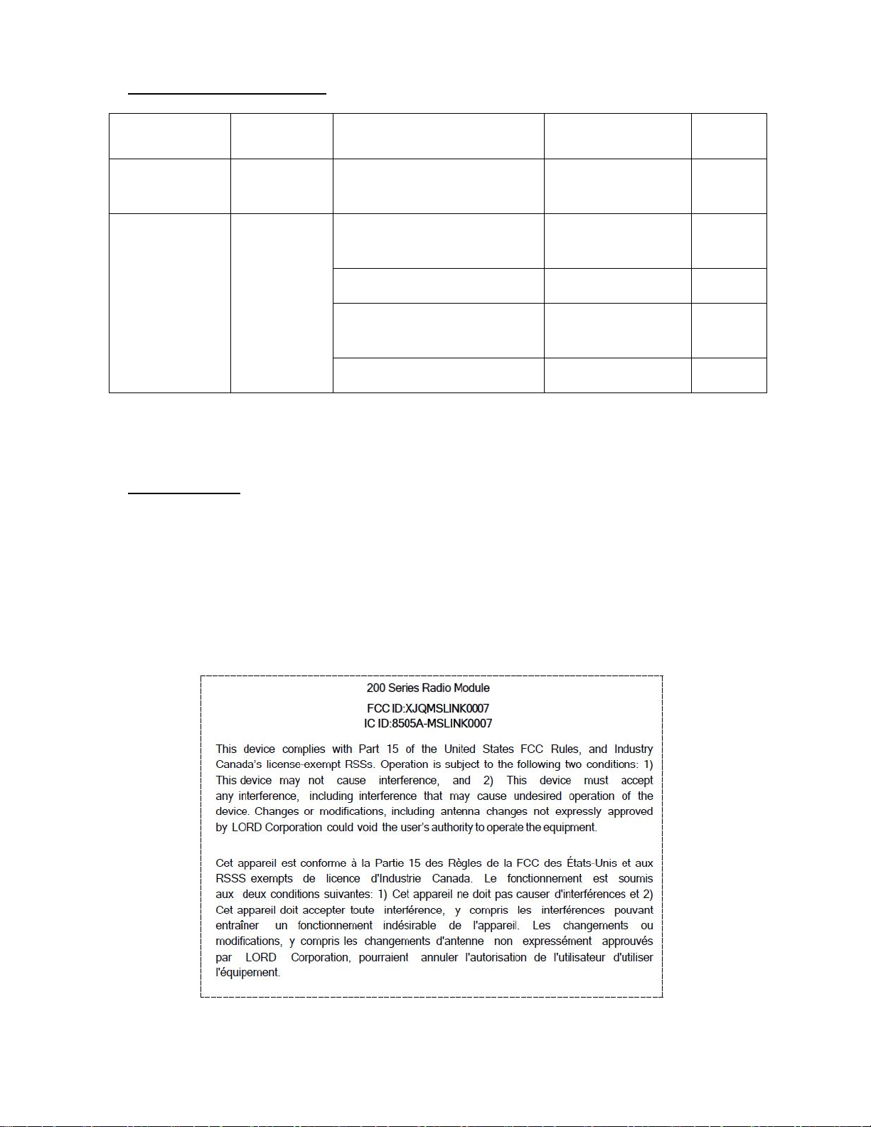
a. Radio modules are labeled with the following FCC/IC ID number.
b. Product assemblies with radio modules in them must be labeled “Contains 200 Series Radio
Module” followed by the FCC/IC ID.
c. The following notice applies to the radio module and must also appear in its entirety in the final
product user manual. In addition, based on the antennas and power parameters specified for this
device, it must be operated at least 2.52 cm from the operator to ensure RF levels do no exceed
what is considered healthy for human exposure.
LORD Corporation 1/15/2018 Revision A Prepared by J. Dunklee
 Loading...