

Page 1
LORCH
LORCH
SchweiBtechnik
GmbH
Im
Anwander
24 -26
D-71549
Auenwald
Telephone:
+49
(0)
71911503-0
Fax:
+49
(0)
71911503-199
Website:
www.lorch.biz
Email:
Operation
Manual
MX
350
EU
909.1900.1-03
Page 2
LORCH
Publisher
LORCH SchweiBtechnik GmbH
Im
Anwander 24 -26,
D-71549 Auenwald, Germany
Telephone: +49(0)7191/503-0
Telefax:
+49 (0)7191 503-199
Website:
E-mail:
www.lorch.biz
[email protected]
Document
number
909.1900.1-03
Issue date 16.10.2013
Copyright
© 2012, LORCH SchweiBtechnik GmbH
This documentation including all its parts is protected by copyright. Any use or
modification outside the strict limits of the copyright law without the permission
of
LORCH SchweiBtechnik GmbH is prohibited and liable to prosecution.
This particularly applies to reproductions, translations, microfilming and storage and
processing
in
electronic systems.
Technical changes Our machines are
in
a constant state of further development, and the right is
reserved to make
technical changes without notice.
Page 3

Table
of
contents
1
2
Machine
elements
......
.
.....
. . 4
Explanati
on
of
symbols
.....
....
4
2.1 Meaning
of
the symbols in the operation
manual . .
......
. .
......
. .
.....
. . . . . . . . . 4
2.2 Meaning
of
the symbols on the machine
...
. . . 4
3 Safety
precautions ... . . ......
..
5
4
Ambient
conditions
.............
5
5
General regulation
of
use ......
. . 6
6
UW
inspecti
on
.......
.....
....
6
7
Unit
protection
. . . .
.....
. .... . . . 6
8 Noise
emission ...
...
. . .
....
. . . 6
9 Electromagnetic
compa
tibility
(EMC) ...........
.....
. .
......
6
10
Transport
. .
...........
. . .
...
. . 6
11
Before start-up .............
...
. 7
11.
1 Fasten transportation belt. . . . . .
...........
. 7
11.2 Fastening accessories bel
t.
. .
.....
. .
.......
7
11.3 Electrode
we
lding process
...
. . . . .. . .
......
8
11.4 T
IG
welding process
...
. . . . . . .
...
.........
8
11.5 MIG welding process . . .. .. .
..............
9
11
.6 Connecting
th
e ground cable
..........
.....
9
11
. 7 Connecting the power supply
...
...
. . .
......
9
12
Start-up
......................
10
12
.1
Electrode welding process . . .
............
. 11
12.2
TIG welding process . . . . . . . . . . . .
........
. 12
12
.3 MIG wel ding process (MIG/MAG}
......
. .
...
12
12.4 Calling up the seconda
ry
parameters
......
..
13
12.5 Special funct ions . . . . . . . . . .
.....
. .
...
. . . 14
13 Graphs . .
.. ........
.........
. 15
13.1 El
ec
trode . . .
....
. . .
...•....
. . . . ..
...
..
15
13.2 TIG
......
......
. ........... . . . .. .
....
15
13.3 MIG (MIX,
C0
2
) . • • •
••.••..•.•.•
.
••••••.
15
14
Messages .
....
. . .
......
.... . .
16
14.1 Status messa ges
........
. . . . . . . . . . . . .
..
16
14.2 Error mes sages .
.....
. .... . . . .. .
.......
16
15
Welding bas
ics
. .... . ....... . . 18
15.1 Stick electrode welding .
...•...
. . . . .
...
...
18
15.2 TIG welding
....
. . . . .. ..
....
. . . . .... .
..
18
16
Fundamentals of the MIG/MAG
welding process
......
.
.......
20
LORCH
16.1 Principle
of
the MIG/MAG welding process . . .
20
16.2 Arc types. . . . . .
........
.... .
.........
20
17
Techn ical data . . .... . ....... . . 22
18
Maintenance and
repair
. .
......
24
19
Disposal ....
.........
........
24
20
Service ......
..
....
. .........
24
21
Declaration
of
conformity
...
....
24
22 Ersatzteilliste I
spa
re parts
list
I
Cm1coK
,a,eTan
ei::t
.............
.
25
22
.1
MX
350
EU ...
....
. .. .. .. .. . . .
...
......
25
23
Stromlaufplan I schematic
I
CxeMaT
HYeCKHH ..............
28
23.1 MX 350 EU . . . . . . . . . . . . . .
...
. . . . . . . .. 28
23.2 Orahtvorscl1ubkoffer I
wire feeder/
6
1101(
no.Qa
Y"1
npOB
OJlOKl-1
MF-07 (EURO)
....
...
. . . . .
...
.
30
24
Anschlussbelegung
I terminal
as
signment
I CxeMa
KOHTaKToe
pa3beMa . .
....
. ......
. . .
...
.
31
10.13 - 3 -
Page 4

LORCH
1 Machine elements
Fig.
1:
Machine elements
1 Mains cable holder
3 Handle (hoisting poi
nt)
4 Operati
ng
field
6 Main swit
ch
7 Remote control connecting socket
8 Connecting socket
plug socket plus/minus (burn-
er/electrode
holder/ground cable)
2.1
- 4 -
Meaning
of
the
symbo
ls
in
the
opera-
tion
manual
Danger
to life
and limb!
If
the
danger warnings are disregarded,
this can cause slight or severe injuries or
even death.
Danger
of
property damage!
Disregardi
ng
danger warnings can cause
damage to workpieces. tools,
and
equip-
ment.
General note!
Indicates usef
ul information about
the
product
and equipment.
Explanation
of
symbo
ls
9 Mains
cab
le
10 Connecting socket wire feed case 7 pin (versi
on
E
U)
CD
Some
depicted or described accessories
are not included
in
the scope
of
delivery.
Subject
to
change.
2.2 Meaning
of
the
symbo
ls on
the
machine
&m
Danger!
Read
the user informati
on
in the operation
man
ual.
Disconnect the
mains
plug!
Pull
out the mains plug before opening
the
housing.
10.1
3
Page 5

Ambient conditions
LORCH
3 Safety precautions
~~~~~~~~~~~~~
Hazard-free working with the machine is
only possible if you read the operating and
safety instructions
co
mpletely and strictly
observe them.
Please obtain practical training before
using the machine for the first time. Heed the
safety regulation
(UVV").
Remove all solvents, degreasers. and other
flammable materials from the weld
in
g area
before welding. Non-movable flammable
materials must be covered.
Only weld
if
the
ambient air contains no high
concentra-
tions
of
dust, acid vapours, gases or flam-
mab
le substances. Special care must
be
taken during repair work on pipe systems
and tanks which contain or have contained
flammable liquids
or
gases.
Never
touch live parts inside
or
outside
of
the housing. Never touch welding electrod
es
or live welding current parts in a
machine that is on.
Do
not
expose the machine
to
rain ; do not
clean with sprays
or
steam jets.
Always use a protection shield when
we
ld-
ing. Warn anyone in the work
area about
th
e dangers or arc rays .
Plea
se
use a suitable extraction system for
gases
and cutti
ng
vapours.
Always
wear
breathing apparatus when-
ever there is a risk
of
inhaling welding or
cutting fumes.
If the power cable is damaged or severed
while working, do not touch the cable, but
im-
mediately pull out the mains plu
g.
Never use
a machi
ne
if the mains cable is damaged.
Keep a fire extinguisher near the welding
area .
Check
the
weldi
ng
area for fire after weldi
ng
(see UW '
).
Never t
ry
to disassemble the pressu
re
reducer. Replace the pressure reducer
if
faulty.
The machine must be transported
or
set up
only on
firm, level surfaces.
T
he maxi
mum admissible angle
of
inclina-
tion for se
tt
ing up or transporting is 1 o
·.
0 Service and
re;pair work may only be carried out by a
trained electrician.
0 Ensure that the
re
is good direct contact
for
the ground
cable immed
iat
ely beside the weld poin
t.
Do not pass
10.
13
the welding current through chains, ball bearings ,
steel cabl
es,
grounding conductors, etc., as it could
cause these to melt.
0 Secure yourself and the welding machine
wh
en work-
ing in elevated or inclined areas.
0 The m
ac
hine should be co n
nec
ted only to a properly
grounded mains suppl
y.
(Three-phase four-w ire sys-
tem with grounded neutral conductor or single phase-
thr
ee-wi
re
system with grounded neutral conducto r)
socket and extension cable must have a functional
protective conductor.
D Wea r protective clothing, l
eat
her gloves and leather
apron.
D Protect the
we
lding area with curtains or
mob
ile
screens.
D Do not use welding equipment to
th
aw out frozen wa-
ter pipes or lines.
D In closed
co
ntainers, under cramped conditions, and
in high electrical risk areas, only use machines with
the
S sign.
0 When taking a break, switch off the machine and
close the valve on the gas
cy
linder.
D Secure the gas cylinder with a chain lo prevent it fall-
ing ove
r.
D Disconnect the mains plug from the mains before
changing the place
of
installation or making repairs
to
the machine.
*) Only appli
ca
ble for German
y.
Can be ordered from
Carl Heymanns-Verlag, Luxemburger Sir. 449, 50939
Koln.
Please heed the safety regulati
ons
which apply to your
country.
Subject
to
change.
4 Ambient conditions
Temperature range of ambient air :
in operation: -20 °C
..
. +40 °c (-4 °F
..
. +104 °F)
transport and storage: -25 •c
..
. +55 •c (-13 "F
..
. +131
"F)
Relative humidity:
up to
so
% at 40 •c
(1
04 "F)
up to 90 % at 20 "C (68 "F)
~
Operation, storage and tra nsport may only
be carries out within the ranges indicated!
Use
outside of this range is co nsidered not
used with its intended purpose. The
manu-
facturer is not liable
for
damages cause by
misuse.
Am
bient air must be free of dust, acids, corrosive gases
or other damag
in
g substances!
-5 -
Page 6

LORCH
5 General regulation
of
use
This machine is intended for use in the commercial and
industrial sector.
It is portable and is suitab
le
for opera-
tion on the mains
supply or also on a power generator.
D The machine is intended for DC electrode welding
of
- unalloyed stee ls, low and high-alloy steels,
-
ni
ckel and its alloys,
D Together with a T
IG
welding torch. the machine is
suitable for TIG welding with direct cur rent
of
- unalloyed steels, low and high-alloy steels,
- copper and its
alloys,
- nickel and its alloys,
- special
metals like titanium, zirconium and tanta-
lum.
D Together with a
wi
re feed case , the machine is suit-
able for MIG welding with
-
solid wire (MIG/MAG),
flux-cored wire.
6
UW
inspection
Operators
of
commercially-operated welding systems
are
obliged to have regular safety inspections
of the
equipment carried out in accordance with EN 60974-4.
Lorch recommends inspections
al
12 month intervals.
A safety i
ns
pection must also
be
carried out if
mod
ifica-
tions or repairs have been made to the system.
G
Improper
UW
inspections can destroy the
system. For more information on
UVV in-
spections
of
welding systems, please con-
tact your authorised Lorch service centre.
7 Unit protection
This machine is protected electronically against overloading. Do not use fuses
of
higher amperage than print-
ed on the identification
plate.
8
Noise
emissi
on
The noise level
of
the unit is less than 70 dB(A}, meas-
ur
ed
under standard load
in
accordance with EN 60974-
1
in
the maximum working poin
t.
- 6 -
Trans
port
9 Electromagnetic compatibility
(EMC)
This product is manufact ured
in
conformance with the
current
EMC standard. Please note the followin
g:
D Due to their high power consumption, weldi
ng ma-
chines can cause
problems in t
he
public power grid.
The mai
ns
connection is therefore subject to requ i
rements with rega rd to the maximum permissible system impedance. The maximum
permissible system
impedance
(Zmax)
of
the interface to the power grid
(mains
con
nection) is indica
ted
in the technical data.
If
in
doubt, please contact your power grid operator.
D The machine is intended for we
ld
ing
in
both commer-
cial and industrial applications (CISPR
11
cl
ass A).
Use in other surroundings (for example
in
residential
areas)
may
disturb other electronic devices.
D Electromagnetic problems during start-up can arise
i
n:
- Mains cables, control cab les, signal and telecom-
munication lines near the weldi
ng
or cutting area
- TV/radio transmitters/receivers
- Computers and other control devices
- Protection equipme nt such as
alarm systems
- Pacemakers and hearing ai
ds
- Measurement and calibration devices
- Equipment with too
little protection against inter-
ference
If other equipment is disturbed, it may
be
necessary to
provide additional
shieldin
g.
D The affected area may go beyond the boundaries of
the property concerned. This depends on the
layout
of the building, and the other activities that may
be
going on there.
Please u
se
the machine
in
compliance with the manufacturer's instructions. The operator of the equipment is
responsible for the installation and use
of
the machine.
Furthe
rm
ore, the owner is responsible (if necessary with
technical assistance from the manufacturer) for
eliminat-
i
ng
the interference caused by electromagnetic fields.
10 Transport
For
tran
spo
rt
usi
ng
mec
hanical l
iftin
g
gear (e.g. cra nes etc.)
only th e handle
may be used as the
hoisting poin
t. Use
suitable load-bearing equipment.
Do
not us
e a
fork-l
ift 1ruck
or sim
ilar
de-
vice
to
li
ft
the
mach
ine
by
its
housing.
The c
ar
rying strap
is
exclusive
ly
for
the
transpo
rt
by a pe
rson
.
10.
13
Page 7

Before start-up
LORCH
11
Before start-up
---------------------------------~~~---------------~-----------------------------
11
.1 Fasten transportation belt
2
Fig.
2:
Transporta
tion belt
2 Ca
rry
ing belt
12 Plas
tic
sli
der
13 Velcro fastener
11
.2 Fastening accessories belt
r1
_ _
~
I
L·
'
~~
, / I / 1
I
~/
'
_,
I
Fig. 3: Accessories belt
5 Accessories belt with fastener
12 Plastic slider
14 Closure
10.13
13
~ Thread the transportation
be
lt into the welding ma-
chine and plastic slides.
See sequence of the num-
bering in
th
e picture.
14
~
Thread
the
accessories belt into the handle and plas-
tic slides.
See sequence
of
the numbering
in
the pic-
ture.
~
Plug the belt fasteners together.
- 7 -
Page 8

LORCH
11.3 Electrode
welding
process
Connecting
the
electrode
welding
cable
:>
Connect the electrode welding cable to the minus
or plus socket 8 and secure the cable by rotating it
clockwise.
The polarity
of
the electrode depends
on
the type of electrode and the welding pro-
cess.
Please follow
the
manufacturer's
instructions on the electrode packaging for
this purpose.
11.4
TIG
welding
process
For TIG weld ing you require
a TIG valve
torch (Type L
TV2600) for this device
Installing electrodes
21
20
:>
Unscrew the clamping cap 17.
:>
Remove the electrode 16 from the collet 18.
:>
Gri
nd
the end
of
the electrode 16.
:>
Slide the electrode 16 into the collet 18.
:>
Insert the electrode 16 into the tor
ch
and firmly tight-
en the clamping cap 17.
Do not
dismantle the collet body 20 and the
gas nozzle 21.
When converting the torch to a different
electrode diameter, please pay attention to
the following.
0 The collet 18, collet body 20 and electrode 16 must
have the same diameter.
0 The gas nozzle
21
must be matched to the electrode
diameter.
Connecting the
TIG
torch
:>
Connect the TIG torch to the minus 8 connection
socket and secure it by turning it
clockwi
se.
- 8 -
Before start-up
Connecting the
inert
gas
cylinder
23
28'\<
I
Fig. 4:
Gas
connection
:>
Place the inert gas cylinder
28
in a suitable location
and secure to prevent it from falling over.
D The cylinder can
be
secu
red
using a wall bracket or
cylinder
trolley.
:>
Briefly open the gas cylinder valve 27 several times
in
order to blow out any dirt particles that are presen
t.
:>
Connect the pressure reducer 22 to the inert gas cylinder 28.
:>
Screw the inert gas hose
24
to pressure reducer 22
and open the gas cylinder
valve 27.
Setting
the
inert
gas
quantity
:>
Open the valve 19
on
the TIG welding torch .
./
Inert gas flows out.
./
The flow met
er
23 indicates the gas quantity, and
the content pressure gauge 26 indicates the cylinder
content.
:>
Close the valve 19 on the TIG welding torch when the
torch is not being used
in
order to prevent unneces-
sary use
of
gas.
10.13
Page 9
Before start-up
11.5
MIG
welding process
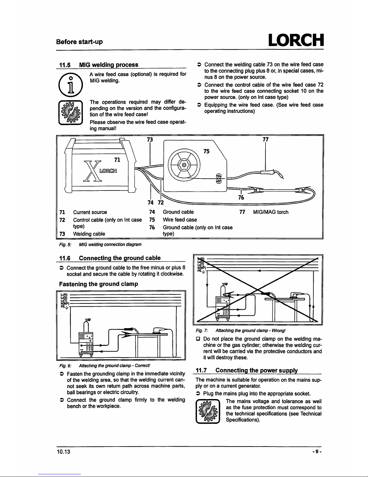
71
A wire feed case (optional) is required for
MIG welding.
The operations required may differ depending on the version and the configura-
tion
of
the wire feed case!
Please observe the wire feed case operating manual!
Current source
74
Ground cable
LORCH
:>
Connect the welding cable 73 on the wire feed case
to the connecting plug plus 8
or,
in special cases, mi-
nus 8 on the power source.
:>
Connect the control cable
of
the wire feed case 72
to the wire feed case connecting socket 1
O on the
power source. (only on lnt case type)
:>
Equipping the wire feed case. (See wire feed case
operating instructions)
77
MIG/MAG torch
72
Control cable (only
on
lnt case
75
Wire feed case
type)
76
Ground cable (only on lnt case
73
Welding cable
type)
Fig.
5:
MIG welding connection diagram
11.6
Connecting the ground cable
:>
Connect the ground cable to the free minus or plus 8
socket and secure the cable by rotating it clockwise.
Fastening the ground clamp
~~~~~~~~~-
~!>""T----------------,,...-
Fig.
6: Attaching the ground clamp - Correct!
:>
Fasten the grounding clamp in the immediate vicinity
of
the welding area, so that the welding current cannot seek its own return path across machine parts,
ball bearings or electric circuitry.
:>
Connect the ground clamp firmly to the welding
bench or the workpiece.
10.13
Fig.
7:
Attaching the ground clamp - Wrong!
a Do not place the ground clamp
on
the welding machine or the gas cylinder; otherwise the welding current will be carried via the protective conductors and
it
will destroy these.
11.7
Connecting the power supply
The machine is suitable for operation on the mains supply or
on
a current generator.
:>
Plug the mains plug into the appropriate socket.
•••
·I
J .
..
The mains voltage and tolerance as well
as the fuse protection must correspond to
the technical specifications (see Technical
Specifications).
-9-
Page 10

LORCH
12 Start-up
51
~--=
~~
:=;;---__,,
50
~
~======:=::-~
49
~,......,...=:
~~fk,
Start-up
38
39
40 41 42
43
~
46
+ -
45
Fig.
8: Control
penel
MX
350
30
The Fault LED
~
ights
up continuously, and the
38
The Synergy LED light sup
if
the Synergy function
fault co
de
is displayed in the 7 segment display
is selected.
35.
39
The MIX LED lights up if MIG welding operating
31
The Remote control LED lights up when a remote
mode with mixed gas is
selected.
control
is connected.
40
The
C02 LED lights up
if
MIG welding operating
Control knob
48
specifies
the
maximum value for
mode with
C02 is selected.
the
control range
of
the remote control.
If
1
OOA
41
The TIG LED lights up if TIG operating mode is
has been set,
for
example, 1
OA
- 1
OOA
can be
called up using the remote control.
selected.
Lights up when wire feed case (case type ln
t)
is
42
Electrode LED
connected
lights up if Electrode operating mode is selected.
32
LEDVRD
43
Electrode CEL LED
lights up continuously with active VRD function
lights up with operating
mode
Electrode CEL
(reduction in idle running voltage) flashes if the
sel
ec
ted (Electrodes w
ith
cellulose-containing
output voltage exceeds the value permitted by
encapsulation,
suitable for vertical downward
the standard (e.g. in welding mode or
if
operating
welding)
mode MSG welding LED 39, 40 selected)
flashes
if gouging operating
mode
selected.
33
The Seconds LED lights up when a value is dis-
44
welding process selector switch
played in the 7 segment
display 35 in
sec
.
serves for
selecting the TIG operating mode,
34 The % LED lights up when a value is displayed in
MIG welding with mixing gas
the 7 segment display
35
in percent.
MIG welding with
C0
2
•
MMA or CEL electrode.
35
7-Segment-Display
If
you hold the button down f
or
longer than 2
indicates the
selected power level, weld voltage
sees
.,
if the MIG (MIX/CO,) operating mode has
or
wire feed speed .
been
selected, the Synergy operating mode is
If
the secondary parameters are activated, the
switched
on
(LED Syner
gy
38
lights up).
code and the set
value are shown alternately.
If
you hold the button down
for
longer than 2
36
Welding volta
ge
LED lights up when the welding sees., if the Electrode (MMA/CEL) operating
voltage is
displayed in the 7 segment display 35 mode has been selected,
the
gouging opera!-
in volts.
ing mode is switched on (LED Electrode CEL 43
37
The Welding current LED lights up when the
flashes).
welding
current is displayed in the 7 segment
45
Polarity indication
display 35 in amps.
46
Polarity indication
-10
·
10.13
Page 11

Start-up
47
Selection button 2
cyc
le/4
cyc
le/cr
ate
r filling
/gas
t
est serv
es for selec
tion
of
2 cycle, 4 cycle
and
cra
ter filling.
If
the button is pushed for longer th
an
2 sees., the
gas test
is
started for approx. 30 sees.
48
The menu I
wel
ding curre
nt
control knob is used
for
:
•
The selection
of
welding current,
wel
ding voltage
and
the
wire fe
ed
rate (press).
•
The setting of welding current, welding voltage
and
the
wire feed rate (turn).
• Calling up
the
secondary parameters (press fo r
2 sees.)
• sel
ect
ing
the seco
ndary parameters (rotate).
• selecting
the
secondary parameters (press).
• setting the secondary parameters (rotate).
49 The Crat
er filling LEDlights
up
if
the Cr
ater
filling
function is
sel
ected
50
LED 2-stroke lights
up
if
you sele
ct the 2-stroke
mode
.
51 LED 4-stro
ke
lights up if
you select
the
4-stroke
mode
.
12.1 El
ectro
de
welding
process
~~~~~~
~~
Switch
on
the
system
:>
Switch on the
sys
tem at the main switch
6.
:>
Keep pressing button 44 until th e desired electrode
operating fun
ct
ion is selected.
./
The ele
ctrode
MMA
or
CEL
(LED 42 or 43) li
ghts up.
:>
Use control
kno
b 48 to set the desired welding cur-
rent.
Electrode 0 [mm]
Recommended current
In·
tenslty [A]
1.5 20
..
.40
2.0
35 .
..
60
2.5
45 ...
100
3.2 75 ... 140
4.0
13
0 .
..
190
5.0 180
...
280
6.0
230
...
370
80
290 .. .420
Tab.
1:
Electrode diameter - Electrode
CD
Please follow the electrode manufacturer's
instructions
Electrode welding cur-
Range
Factory set-
rent
ting
Welding
current
11
10
to 350A 100
Tab
. 2: Electrode welding current
LORCH
Arc
ignition
:>
Briefly touch the workpiece at the point
to
be
welded
us
ing
the
electrode and li
ft
the
electrode a little.
./
The arc burns between t
he
workpiece and the elec-
trode.
Hotstart
0 Ignition performance is
improve
d by increasing t
he
welding current (Hotstart).
:>
Press the
ope
rating button
48
for 2 sees. to call up
the sec
ondary parameters.
:>
Selec
t the secondary parameter Hotstart (Code "ISt")
by
rotating
the
control
kno
b 48.
:>
Confirm the secondary parameter
by
pressing
the
con
trol knob 48.
:>
Set the
des
ired value
by
rotating the
con
trol knob 48.
:>
Confirm t
he
setting by pressing the control knob 48.
:>
Repeat the ope rations for setting the Hotstart ti
me
''
tSt
" secondary parameter.
:>
Exit the secondary parameters by pushing the oper-
ating button
48
for
2 sees.,
or
by
pressing
the
selec-
tion button 44.
Arc
dynamics (Arc
Force)
0
The
electro
de
is prevent
ed
from burning in in the
weld pool
by
means
of a br
ief current increase with
a
short
arc.
:>
Press the operating button
48
fo
r 2 sees. to call up
the secondary parame t
ers
.
:i
Select the Arc dynamics secondary parameter (Code
"dAF")
by turning the control kn
ob
48.
:>
Confirm
the
sec
ondary parameter by pressing the
control knob
48
.
:>
Set the desired
value
by rota
ting t
he
control knob 48.
:>
Confirm t
he
setting
by
pressing the control knob 48.
:>
Ex
it the secondary paramet
ers
by push
ing the
ope
r-
ating button 48 for
2 sees
..
or
by pressing t
he
selec-
ti
on
button 44.
10.13 -11 -
Page 12

LORCH
12.2
TIG
welding
proces
~
Switch on the
system
:>
Switch
on
the system at the main switch 6.
:>
Keep pressing button 44 until the desired MIG oper-
ating function is
selected.
./
The TIG symbo l (LED 41) lights up.
:>
Use control knob 48 to set the desired welding current.
TIG
welding current
Range
Factory
setting
Welding current
11
10
to
350A 100
Tab.
3:
TIG
welding current
Arc
ignitio
n
:>
Open the valve
19
on the TIG welding torch.
CD
(
~
( p
'//////////////
'///
///////////
:>
<D
Briefly touch the workpiece with the tip
of
the elec-
trode
at
the point to be welded.
:>
@
Lift
the electrode a littl
e.
./
The
arc burns between the workpiece and the elec-
trode.
Ups lope
O A short-circuit current of 60 A
is
used for igniting during
the
TIG welding proc
ess.
The upslope takes place with
115
Ns
unt
il
the set welding current is reached.
Guideline values
for
the
current
intensity
and
the
gas
quantity
Tungsten electrode Current in-
Gas quantity
diameter [mm]
tensity [A]
[Vmin]
1.0 3 .. .40
4
1.6 15
...
130
5 ... 6
2.0
45 .
..
180
5 ... 8
2.4
70 ... 240 6 ... 10
3.2 140 .
.. 320
6
...
12
4.0 220 .. .450
6 .
..
14
-12
-
Start-up
12.3
MIG
welding
process
(MIG/MAG}
__
Switch
on
the
system
:>
Switch on the system at the main switch 6.
Selecting the
welding
process
:>
Kee p pressing button 44 until the desired MIX
or
C0
2
operating function is selected.
./
The MIX
or
C02 symbol (LED
39
or
40) lights up.
Selecting the
wire
feed
case
CD
The type
of
connected wire feed case can
be
selected at the welding unit.
0 If you are using a wire feed case with its own contro l
system you must set the case type
lo
external (EXI).
O If
you a
re
using a wire feed case without its own con-
trol system (with 6
or
7 pole connection plug) you
must set the case type
to
internal
(lnt).
:>
Press the operating button
48
for 2 sees. to call up
the secondary para meters.
:>
Select the case type secondary parameter (Code
"Fdt") by turning the control knob 48 .
./
The
parameter
code
and
the
correspon
ding
setting are
displayed alternately
in
the
7-Seg
ment
display 35.
:>
Confi
rm
the
secondary
parameter
by
pressing
the
control knob 48 .
:>
Set the desired case type by
rot
ating the control knob
48 .
./
"lnt" or "
EXt"
is displayed
in the
7 segme
nt
display
35.
:>
Confirm the setting by pressing the control knob 48.
:>
Exit the secondary parameters by pushing the oper-
ating button 48 for 2 sees
.,
or
by
pressing the selec-
tion button 44.
Operating mode EXt case
type
O Only the 2 cycle operating mode is possible in the
case type
E.Xt
operating mode.
:>
Set the welding voltage by rotating the control kn
ob
48
.
:>
Press the operating button 48 to display the welding
current.
O The welding current is only displayed during welding.
Operating mode
lnt
case
type
:>
Keep pushing the button 47 until the desired operating mode 2
cycle or 4 cycle an
d/or
crater filling func-
tion is selected .
./
The
LEDs
50
or
51
and/or 49 light up.
:>
Set the desired welding vol
tage
by rotating the knob
on the feed case.
:>
Set the desired wire feed speed by rotating the knob
on the feed case.
10.13
Page 13

Start-up
O Press the operating button 48 to sw itch between the
display
of welding voltage, welding current and wire
feed speed.
./
The
rel
eva
nt parameter value is displayed
in
the
7 seg-
ment
display 35.
0 The welding current is only displayed during welding.
Synergy
~
Press the selector button 44 for 2 sec. with the oper-
ating mode
MIG
selected.
./'
The Synergy
38
LED lights up.
CD
The set wire diameter is displayed for approx. 5 sees. after switching on or
selecti ng
the Synergy operat ing
mode
.
:>
Select the wire diameter parameter as follows
- Press the operating button 48, whilst the wi
re
di-
ameter
"d" is displayed in the 7 segment display.
(immediately
after switching on or selecting the
Synergy operating mode)
- or select the secondary para
meter
wire diam-
eter during subsequent operation (see
"13.3 MIG
(MIX,
C02)"
on Page 15)
:>
Set the wi
re
diameter by rotat ing the control knob 48.
:>
Confirm the setting by pressing the control knob 48 .
:>
If necessary, press the control knob 48 for 2 sees., or the
sele
ct
ion button 44
to
exit the secondary parameters.
:>
Set the desired weldi ng voltage by rotating the kn
ob
on the feed case.
:>
Set the wire feed rate on the rotary knob on the feed
case to
the mid
dle position (0).
D
In the operating mode Synergy, the wire feed rate is
automatically matched to the set welding voltage.
:>
Correct the wire feed rate, if necessary, on the feed
case by
tu
rning
to"+" or"-"
.
12.4 Calling up
the
secondary parameters
:>
Press the opera ting button 48 for 2 sees. to call up
the secondary parameters.
:>
Set the desired secondary parameter by rotating the
control k
nob
48
.
./
The
parame
ter
code
and
the corresponding setting
are
displayed alternately
in
the 7-
Segment
display 3
5.
:>
Confirm the secondary parameter by pressing the
control knob
48
.
:>
The setting
ea
n be adjusted by rotating the control
knob 48.
:>
Confirm the setting by pressing the control knob 48.
:>
The previous
or
next secondary paramet
er
is dis-
played by rotating the control knob 48.
D Different secondary parameters are
available de-
pending on
the
selected operating mode and func-
tion.
:>
Press the contro l knob 48 for 2 sees.,
or
the selection
bulton 44 to ex:it the secondary parame
te
rs.
10.13
LORCH
Cl)
Mode
::J
Cl)
iii
en
~
c
ea
Cl>
>
ea
Cl>
::J
..
e
Parameter
'8
"E
c
en
(!)
c
ea
0
Cll
c
~
i=
;;;
:::!:
"C
=
c
0
(!)
Cll
G>
iii
-
"'
i
i
"'
Start current
I t Sll:I
50 %
5
..
. 200 % x
Start current
tim
e
fTSlB
0.1 s
O.O
to
x
2
0s
Hots tart
LJjSLt_
1
25% 5 ...
200 % x
Hotstart time
~TSlf
1.
0 s
O.Oto
x
20 s
Arc dynamics
ld
lA1F
100 %
0 ... 200 % x
The weld
ing current increases automatically as the weld-
ing
voltage is reduced. The arc dynamic indicates the ratio
between the
welding current and the automatic increase.
Arc end detection
RlEJdJ
100%
0 ... 200 %
x x
Yo
ur welding machine switches the welding current o
ff
al
a certain arc length.
(We
ld
end
detection). The maxim
um
length of the arc can be adapted using the "AEd" paramet er.
Inductor effect
I ll
nd
I
100%
0 .
..
200 % x x
Time
bum back
!:b
ib
100 % 1 ..
.2
00 % x x
Crater filling energy
1
i(if
50 % 0 ... 100 %
x
Crater filling voltage
UJll
20V
10 to 40
x
v
Crater filli
ng
feed
tf_iE
5 0 .
..
18
x
ra
te
m/min m/min
Crater filling lime
It
Flt
1 s 0
to
10 s x x
(on
ly with 2 cycle)
Case
ty
pe (feeder
f
ldlf
lnt ln
t...
EXI
x x
type)
Cre
ep in speed
_C
ISIP
2 2 ... 18
x x
mlm
in
m
/m
in
Wire diameter
di
I
~~
0.8 .
.. 1.2
mm
x
Tab.
4:
Secondary parameters
D The factory setting values a
re optimised thanks to
automatic parameters.
You
can use these factory settings unchanged for
most
we
lding jobs.
-
13
.
Page 14
LORCH
12.5 Special functions
Gouging
Cl
Gouging is used for working out the roots
or
faulty
points and serves for preparing the weld seam.
Cl
A special torch
is
required for gouging that has car-
bon electrodes and compressed air connection.
:>
Keep pressing button 44 until the desired electrode
operating function (MMA or CEL)
is
selected .
./
The electrode MMA or CEL (LED 42 or 43) lights up.
:>
Press and hold the electrode button 44 for at least 2
seconds .
./
The Electrode CEL LED 43 flashes.
:>
Set the desired current by rotating the control knob
48.
Master reset
CD
Warning! All personal settings will
be
lost
All welding and secondary parameters are
reset to their factory settings (master reset
function).
:>
Press buttons 44 and 47 simultaneously for at least
3 seconds .
./
The 7 segment display and the control panel indicators light up briefly as confirmation.
Switching the Function lock on I
off
:>
Press the control knob 48 and the button 44 simultaneously for at least 3 seconds .
./ 0--
11
is briefly displayed
in
the 7 segment display 35
as confirmation .
./
All buttons on the control knob are blocked. If it is
operated,"--"
is displayed.
Cl
The control knob 48 and button 44 must be pressed
again for at
least 3 seconds
in
order to disable the
function lock.
-14-
The function lock setting is saved! If the
machine is switched off with the function
lock activated, the control panel is still
blocked when the machine is switched
back on.
Start-up
10.13
Page 15

Graphs
13
Graphs
13.1
Electrode
I Current
11
Welding
current
ISt
Hots tart
t
Time
tSt
Hotstart time
13.2
TIG
I Current
11
Welding current
ISt
Start current
Iz
Ignition current
t Time
tlu Upslope
tSt
Start current time
13.3
MIG (MIX,
C0
2
)
tbb
Tim
e burn back
CF
Crater filling energy
I
Current
11
Welding current
IC
FU
Current (crater filling voltage}
t Time
tCFt
Cra
ter filling time
v Speed
vCFF Speed crater filling
feed
rate
vCSP Creep in speed
t
I
;
I
S!
'
!S
t
Fig.
9: Electrode current routing diagram
t
I
I
!lz
IS!
I
'
:
l
'
'
tlu
:
'
tSt
I
'
,•
~:·
~
·
'
'
Fig.
10:
TIG
current routing diagram
t
I
(A)
11
!I
(mfmin)
vCS
P
'
11
LORCH
11
ICFU
!CF
t
-+
t-+
ICFt i I-+
: (
s)
'
~
:
tbb
.....___.____,;
vCFF
t-+
(s)
Fig.
11: Current development diagram MIG (MIX, CO.)
10.13
·15·
Page 16

LORCH
14 Messages
14.1 Status messages
'--
~~~~~~~~~-
0
An
enror code
is
displayed in t
he
7-segment display
in the event
of
a malfunction. You
can
switch
over
between error code and sub-error (sub code) in
the
7
segme
nt display
by
pushing the button 44.
Code
Note
Cause
HOS
Short-circuit Short-circuit in the output circuit
Messages
After
the
message
has
been output, the
machine
will only function to a limited ex-
tent; the error
must
be corrected
as
quick
ly
as
possible.
The status message can
be delet
ed by
pressing
the
control knob 48.
P
ossJb
le
remedy
Eli
minate the short-circuit (pick up
electrode holder, ... )
H30 Configuration
Component group recogniti
on
faulty Inform Service
H31
Communication CAN bus communication faulty
Check connected devices and CAN
connections
H34 Fans Fan curre
nt
faulty Inform Service
Tab.
5: Status messages
14.2
Error
messages
0
An
error
cod
e is displayed in the 7-segm
ent
displ
ay
in
the
event of a malfunction. You can switch
over
between error code and sub-error (sub
code) in the 7
segmen
t displ
ay
by
pushing a
ny
button.
CD
As
long
as
there is
an
error
code
on
dis-
play
weld
ing is not possible.
Code.
E11ror
Cause
Possible
remedy
E01
Excessive temperature Duty cycle exceeded Allow switched-on machine to cool
down for a few minutes
Dust
fi
lter contaminated Replace dust filter
E02
Overvoltage
Mains
voltage too high Check mains voltage
E04-1 Protective earth conductor
Fault
current to protective earth con- Connect the welding earth lead
monitoring ductor
E06
Overvoltage secondary Initial voltage too high
Inform Service
E07 EEPROM
Communication with EEPROM defec-
Switch machine
off
and on again, ex-
tive ecute master reset
E08-1
Excess motor voltage
Motor voltage too high
Inform Service
E08-2
Motor power supply
Err
or
in motor power supply Inform Service
E08-3
Overcurrent
on
motor
Motor current continuously t
oo
high Reduce motor load
EOS
-10 Torch connection
Torch/torch connection error
Check torch and torch connection.
Switch the equipment off and
on
again
E08-11
VII
acquisition
Voltage/current measuring systems
Inform Service
faulty
E09
Vo
ltage detection
Voltage measuring system
faulty Inform Servi
ce
E12 Power section
Power section start-up
fa
ulty
Inform Service
E13
Temperature sensor Temperatu
re
sensor not ready for
Inform Service
operation
E14
Supply voltage
internal supply voltage too low Check mains voltages
E15
Current detection
Error during curre
nt
measurement Inform Service
E18
I Overload protection
Safety switch device to protect elec-
Inform Service
trical
components
•
16.
10.13
Page 17

Messages
LORCH
Co
de
Error
Cause
Possible
remedy
E
22
Mains undervolta9e
Mains voltage
on
power unit is t
oo
Check mains voltag
es
low
E25
Idle generator Idle generator raulty Inform Servi
ce
E30
Error config uration
Faulty or wrong
pc-
board, wrong
Inform Service
software
system
installed
E
31
Communicat ions fault CAN bus
commu
nication faulty Switch the equipmen t off and on again
E32
FP
GA
FP
GA
faulty Inform Service
E
33
Power section
Power
module
not
symmetrical Inform Service
E34
Fans
Fan current
fa
ulty Info
rm
Service
E40
Voltage detection
Voltage measurement faulty
at
the Inform Service
socket
Tab
. 6. Error messages
10.13 - 17 -
Page 18

LORCH
15 Welding basics
15.1
St
ick
electrode
wel
din
g
<-------
Coated stick electrodes are used for the widely-used
manual metal arc welding process (stick electrode
weld-
ing). The coating
of
the electrode melts off during the
weldi
ng
process together wi
th
the co
re
wire. T
he
coating
gene
ra
tes the shielding gas. Additionally the burningoff coating compensates alloy elements. which are destroyed
in
the molten pool. A slag layer forms on top
of
the welding seam. which covers and protects the cooling
welding se
am
against the air.
The coatings
of
the electrodes differ according to thick-
ness and type, i.e. chemical composition. This results
in
different welding properties and con
seq
uently different
applications for t
he
e'lectrodes. Types a
nd
nomenclature
a
re
defined in DIN EN 499 (formerly 1913) .
-'---
Stick electrode
Base
metal
15.2
TIG
weld
ing
The TIG welding process is a universally-applicable process which creates high quality joint
s.
T
he
electrode
of the
TIG process consists
of
non-melting
tungsten, t
he
shielding gas is an inert gas. In English
usage we
sp
eak
ofTIG
welding ("Tungsten" = Wolfram
).
Inert gas is chemically neutral and does not react with
the weld meta
l.
Inert gases are, e.g. argon, helium and
their mixtures.
Usually pure argon (99.9%) is used. The
welding g
as
must be dry. DIN 32 526 defines the differ-
ent types of shielding gas.
TI
G wel
ding
process basics
A non-melting tungsten electrode is clamped with a collet into a
gas
or water-cooled torch . The arc burns between the tungsten electrode and the workpiece in an
inert
shielding gas atmosphere. Thus the tungsten electrode acts as an arc carrier. The arc melts the workpiece
point by point and forms the weld pool. The shieldi
ng
gas
escapes through the gas nozzle. This gas protects the
tungsten electrode, the arc and t
he
molten pool against
t
he surrounding air. This prevents undesired oxidation.
Con
seq
uently, poor welding results may occur due to
tro
ub
le with the shielding gas supply.
In case additional filler material is required. filler
~1\re
is supplied either manually, as
in
gas name weldin
g,
or
-18
-
We
lding
basics
automatically
by
means of a cold wi
re
feeder. The filler
wire must be equally or mo
re
highly alloyed than the
base mater
ia
l.
Fla
nge and corner welds can be created
easily without filler wire.
Sh
ieldi
ng
gas
B
as
ically, both DC and AC may be used for TIG welding.
The current mode and pol
ar
ity depend on the material to
be welde
d.
No
n or low-alloyed steel, high-alloyed steel and copper,
as
well as titanium a
nd
tantalum are welded with DC.
The electrode is connected at the minus pole because of
the stronger
cu
rrent loading.
When we lding aluminium and nnagnesium as well
as
their alloys,
AC
must be used in order to tear up the high-
melti
ng
and tough oxide skin which forms on the molten
pool or which is present on the base
metal. If t
he
oxide
skin is missin
g.
e.g. there has been welding on the same
part for a longer tim
e,
the arc can
be unsta
ble or break
up from time to
time.
Shape of the electro de
tip
Tungsten electrodes always have to be ground lengthwi
se
because crosswise grind
ing marks cause an un-
steady arc.
10
.13
Page 19

Welding basics
Weldi
ng
current [A]
10-
50
50-
200
> 200
10.13
Electrode
angle
15
°-30
°
30°
-45
°
45
° - 75°
LORCH
The shape
of
the electrode for DC welding has to be
and remain as sharp as a penc il. The angle
of
the point
depends on the
we
ldi
ng
current. When AC welding, ii is
suffici
en
t to sharpen the edge
of
the electrode slightly.
After a short time, a round to slightly convex form is built.
If the electrode tip is polluted due to dipping into the weld
pool or touching the filler wi
re
, the respective part
of the
electrode must be completely ground off. Restore t
he
original, pointed shape. Grind in longitudinal direction.
- 19 -
Page 20

LORCH
Fund
amentals
of
the MIG/MAG welding process
16 Fundamentals of the MIG/MAG welding process
-~"'--'"~~~~~~~~~~~~~~~~
16.1
Princip
le
of
the MIG/MAG
welding
process
The wire feed rollers feed the wire electrode from the
reel to the contact tip.
An
arc is created between the wire
electrode
and
the workpiece. The wire electrode thus
becomes the arc carrier. The arc
melts the workpiece
point by point and forms the
weld pool. The wire elec-
trode melts a
nd
drips into the weld pool, thus formi
ng the
filler metal. The inert gas flows from the gas nozzle and
protects the arc and
weld pool from atmospheric gases.
Wire electr
od£--
-
-:
G
as
noz
--
-
---"
~Bntact
ti~:-=~
~~~
Sh
ielding
-,..--
-===--
___,.~
gas
Welding
,._flem
Fig. 12: MIG/MAG welding process
es
(!>
Powe
r source
t:I
There a
re
two types
of
metal shielding-gas welding
that are different
iated
by
the type
of
shielding
gas
that
is used:
metal inert gas welding (MIG), inert shielding
gas) and metal active gas weldi
ng
(MAG, active shield-
ing gas
).
Welding
Shielding
gas
process
inert
active
MIG
Helium
(He) Argon
(Ar)
mixture
of
Ar/He
MAG-C
Carbon dioxide
100 %
C02
MAG-M
Mixtures of Ar/
C02Ar/02
Tab.
7:
MIG/MAG welding processes
The welding processes are further differentiated by arc
type. T
his
means that there are differences
in
the form of
the arc, short circuit tendency and
metal transfer mode.
Selection
of
the type
of
arc is only possible to a limited
extent e. g. when short arc welding. Short arc welding is
possible using all metal shielding gas welding processes
by the
selection of the suitable current intensity and the
associated arc
voltage, although the short circuit frequency and drop size are very different, according to the
shielding gas being use
d.
- 20 -
16
.2
Arc types
Short
arc
This type of arc is particularly suited to the welding
of
thin sheets, in root layers and for welding in restricted
locations because
of
its relatively "cold" weld flow.
In this
case, the
weldi
ng
takes place with a very short arc. at
low arc voltage and
at
low cu
rre
nt intensity. Due to the
su
rf
ace tension of the melt pool, t
he
drop is drawn into
the
molten
metal and the arc is reignite
d.
This recurring
cyc
le
creates a continuous alternation between the short
circuit and the arcing period.
CD
The transition from short to spr
ay
arc is de-
pendent upon the gas mixture and the wire
diameter.
Transiti
on
arc
A transi
ti
on arc is used for medium plate thickness and
for vertical down
welds. The materi
al
transfer tales place
both in short ci
rcu
it and in free flow. This produces a re-
duced short circu
it index and a slightly "hotter" mol
ten
pool than
in
the short arc. Transition arc welding has a
higher
melting rate than short arc, a
nd
is therefore more
economical.
Long
arc
Lo
ng arcs are typically used for welding under carbon
dioxide and under high
C0
2 containi
ng
gas mixtures
in
the upper performance range. Long arc welding is not
re
ally suitable for welding in tight spaces. Larger drops
fall into the molten pool largely by gravi
ty.
This some-
times involves short circuits whic
h,
al
the point or the
short circuit,
ca
n produce spatter when the arc ignites
again. because of the
upslope.
Spray arc
Due to the thinness
of
the melt pool, spray arc welding
is not suitable for welding
in
tight spaces. It is used for
welding in the high
er
power range using inert gases or
gas mixtures with high argon conten
t.
The spray arc has
a very fine dro
p,
short-circuit free material transfer.
10.13
Page 21

Fundamentals
of
the MIG/MAG welding
proce
ss
LORCH
W
ire elec
-
L
ong
ar
c/
Tr
ansitio
n
tr
ode di-
S
hort
arc
a
meter
spray
arc
arc
mm
A
v A
v A v
0.8 1
40
...
23
...
110
..
18
...
50 ...
14
..
180
28 150
22
130 18
1
.0
180 ...
24 ...
130 ...
18 ... 70 ... 16 ...
250
30
200
24
160 19
1.2
220 ...
25
...
170
...
19
... 120
...
17 ...
320
32
250
26
200
20
1.6 260 ... 26 ... 200
...
22 ...
150 ...
18
...
320
34
300
28
200
21
Good
weld qualities are only achieved if the voltage and
cu
rrent are well balan
ced
.
VVhen
using
C02
an arc voltage whi
ch
is a
rou
nd
3 V larger
than required when u
sing
argon-
rich
gas mixtures.
Tab
. 8: Working ranges for MAG welding
Hol
ding
and
guid
ing the torch
CD
With metal shielding gas welding, you can
n
o work in all posi
ti
ons: level, horizontally,
vertically
from top to bottom, vertically from
bottom to to
p,
overhead and in lateral posi-
tion.
For
level and horizontal and level welds, hold the torch
vertically (neutral torch position)
or
pushing
at
up to 30°.
On
thicker layers you can also drag the torch slightly.
The neutral torch position produces the best penetration
depth and inert gas coverage. Take care not to
tilt t
he
torch too much, otherwise air could
be dra
wn in
to
the
inert
gas
shie
ld
by the injection effect.
If you are welding vertically and overhead then you
should push the torch slightly. Down welds are used
mainly for welding thin plates. In this case, hold the torch
in as
neutral or slightly dragging position. This technique
requires specially trained and experienced
welders,
since there are dangers from incomplete fusion due to
the forward melt
pool. This danger increases wi
th
thicker
materials, or
if
the melt pool is very thin because the volt-
age is too high.
We
ld direction pushing
We
ld directi
on dra
ggi
ng
Fig. 13:
Torch
position
Avoid larger oscillating movements in order
to
prevent
the melt pool from buildi
ng
up
in
front of the arc. This can
lead to incomplete fusion due to the forward melt pool.
Exc
ept
in the vertical up position. you should oscillate
laterally only
as
far necessary to cover both edges
of
the
10.13
seam.
If
the seam is sufficiently wide, weld two beads
alongside each other.
If you are welding in the vertical up position, your oscilla-
tions should be in
the
shape of an open tri angl
e.
Arc length
The longer the arc. the shallower is the penetration
depth, the wid
er
and flatter the weld bead and the great-
er
the tendency to spatter. The weld metal
is
transferred
in
slightly larger drops compared with a shorter arc. Use
a longer
arc
when fillet welding, in order to produce a flat
or concave
weld bead.
A shorter arc increases the penetration depth (at t
he
same current intensity), the weld bead is narrower and
the tendency to spatter is reduced. The weld metal is
tra
nsf
erred in finer drops until the short a
rc
is
reached.
Lo
ng
arc
Short arc
Fig. 14: Arc length
Electrode
wire
length
In general, the distance between
the
torch
and
the work-
piece is 10-12 times the wire diamete
r.
You can also
change the torch distance to affect the length of
the
free
end of
th
e electrod
e.
A longer fre e end
of the
electrode reduces the current
intensity and the pe netration dept
h.
A shorter free end of the electrode increases the current
intensity
while maintaining the same wire feed rate.
Lo
ng
electrode end Short electrode end
Fig.
15: Electrode wire length
-
21
-
Page 22

LORCH
Technical data
17
Technical data
Technical data
1
'
Units
MX35
0AS
/
MX3SOVRD
EU
EU
TIG weldlng
A
10
...
350
Welding range min - max
v 10.4 ... 24.0
Idle voltage (peak value
in
accordance with EN 60974-1) V/DC <113 -
Idle voltage VRD (in accordance with
rocr
12.2 007.8) V/DC
-
12
Current setting Infinitely variable
Slope characteristic falling
Welding
current
at
ED 100% A 250
Weldi ng current at ED 60% A
300
ED at maxim
um welding current
%
40
Current consumption 11 (at ED 100
%)
A
12.3
Current consumption I, (at ED
60
%)
A 15.7
Current consumption I, max A 19.6
Ma
ximum effective mains current
(I
,.")
A
12.
4
Power consumption S, (at ED 100%)
kV
A 8.5
Power consumption S1 (at ED 60%)
kVA 10.9
Power consumption S, """'
kVA 13.6
Electrode welding
A
10
... 350
Welding range min - max
v 20.4 ... 34 0
Idle voltage (peak value
1n
accordance with EN 60974-1) V/DC
<1
13
-
Idle voltage VRD (in accordance with
rocr
12.2 007 .8)
V/DC
-
12
Current setting
Infinitely variable
Slope characteristic falling
Weld ing curr
ent
al
ED
10
0%
A 230
Welding current at
ED
60%
A 280
ED at maximum welding current
%
35
Current consumption I, (at
ED
100%) A 16.0
Current consumptio n 1, (at ED 60%) A
20.7
Current consumption 11 max A
27.5
Maxim
um
effective mains current (I 1eff )
A
16
.3
Power consumption S, (at
ED
100%) kVA
11.1
Power consumption
s,
(at ED
60
%)
kVA
14.3
Pow
er
consumption
s,
max kVA 19
.1
Weldable electrodes
mm
1.5
...
8.0
MSG welding process (MIG/MA
G)
A
10 ... 350
Welding range min - max
v
14
.5 ... 31.5
Idle voltage (peak value in accordance with EN 60974-
1)
V/DC
<1
13
Power setting Infinitely variable
Slope
characteristic
falling
- 22 -
10.13
Page 23

Technical data
LORCH
Tec
hnical
data
1
)
U
nits
MX 350AS/ MX 3
50V
RD
EU
EU
Welding current
at
ED 100%
A 230
Welding
current
at
ED 60%
A
280
ED
at
maximum welding current
%
35
Current
consumption 11 (
at
ED 100%)
A
15.9
Curr
ent
consumption I, (at
ED
60
%)
A
20
.1
Current consumpti
on
I, max
A
27
.8
Maximum effective mains current
(11.n
)
11eff I A 16.4
Power consumption
s, (at ED 100%)
kVA 11.0
Power consumption S, (at ED 60%)
kVA
13.
9
P
ow
er consumption S, "''"
kVA
19.3
We
ldable wires
steel
0 mm 0.8-1.
2
Weldable wir
es aluminium
0 mm
1.0 -1.2
We
ldable wires
CuSi
0mm
0.
8-1
.2
Efficiency
I')
at
100% ED
%
87
Mains
Mains voltage v 400 /
3-
Mains frequency
Hz
50
... 60
Positive mains tolerance %
25
Negative mains tolerance %
30
Negative mains tolerance, temporary %
40
Mains connection
mm•
4 x 2.5
Mains
plug
CEE32
Curren t consumption I, ,
0•10
11<1
A 0.2
Mains fuse slow -response TIG/EL
A
25
Power factor cos
<p
12 max
cos
<p
0.99
Power factor
J..
(
at
12max)
"
0.87
Max. pe rmissible syst
em
impedance Zmax in ace with I
EC
61000-3-11/12 mO 44
Machine
Protection class IP
34
Insulation class F
Cooling method F
Noise emission
db
{A) <70
Standard
EN
60974-1
Designation
CE
, S
Di
mensions
and
weights
Dimensions power source (LxWxH)
mm
515 x 185 x 400
Weight of power source kg 18.6
Tab
. 9:
Technical
datao
ED
=
Switch-on
duration
1
1 measured at 40"C ambient temperature
10.13 -
23
-
Page 24

LORCH
18 Maintenance and repair
-----
Please !heed the
current
safety
and
ac-
cident
prevention
regulations
during all
maintenance
and
repair
work.
ine requires a minimum of care and maintenance. Only a few items need to be checked to ensure
trouble-free
long-term operation.
:>
Check the following points f
or
damage
bef
ore starting
up the
welding machine,
- Mains
plug
and
cable
- Weldi
ng
torch and connections
- G
ro
und cable and connection
- Keyboa
rd
membrane and control panel
:>
Check the dust filter every two month
s.
-
Sw
itch the machine off
- Disconnect the mains
pl
ug
- Unscrew the ventilation grid on the rear side
19 Disposal
0
Only
for
EU
cou
ntr
ies.
Do not dispo
se
of
electric tools together
with
household waste material!
20 Service
Lorch Schwe
iBt
echnik GmbH
Im Anwander 24 -
26
D-71549 Auenwald
Germany
Tel.
+49 (0)71
91 503-0
F
ax
+49(0)7191 50
3-1
99
21
Declaration of conformity
We herewith declare that this product was manufactured
in conformance wit h the
following standards or official
documents:
EN
60
974
, EN
61
000-3-2, EN
61
000-3-3
in conformance with the guidelines 2006/95/EG.
2004/108/EG, 2011/65/EU.
c ( 2012
Wolfgang
Grob
Managing Director
Lorch
SchweiBtechnik GmbH
-
24
-
Declaration
of
conformity
- Check the dust filter for pollution
- Replace the dust filter
if
it is polluted (dust filter:
Order
number 612 .5193.0)
Use only original Lorch spare parts for
maintenance and repair.
If you experience problems
or
need re-
pairs, contact a dealer authorised by Lorch.
Never ma
ke
repairs or technical changes
yourself. In this case the manufactur
er'
s
war
ra
nty is
no
longer vali
d.
In observance
of
European Directive 2002/96/EC on
wast
e,
electrical and electronic equipment and its implementation in accordance with national law, electric tools
that h
av
e reached the end of their service life must be
collected separately and returned
to an environmentally
compatible recycling facility.
10
.1
3
Page 25

Ersatzteilliste I spare parts
list
I Cm1coK AeTaneiil
LORCH
22 Ersatzteilliste I spare parts list I
Cm1coK
AeTaneM
~~~~~~~~~~~---'
22.1 MX 350 EU
990.4472.6-00
MX 350 (EU)
10.13
9
1
\
3
(~))
1=
\
~-~~
42
39
\~
'-.
'·
.,.-
8
10
19
- 25 -
Page 26

LORCH
Ersatzteilliste I spare parts list I
Cm1
coK
AeT
ane'1
990.4472.6-00
MX 3
50
(EU)
P
os
Mat
.Nr. Bezeichnung
desi
gn
ation
Ha3eaHMe
1 604.3609.0 Zubeho
rgu
rt
40x800 schwarz transportation belt 40x800 black
PeMeHb
Af'IR npHH
aAf'le>KHocrelil
G22
G22
40x800
YepHbllil G22
2
604.3613.0
Tragegurt 40x1500 schwa
rz
transportation belt 40x1500
PeMeHb
AflR
ne
peHOCKH
G22
black
G22
40x1500
Yep
. G22
3
604
.3640.0
KUNSTSTO
FFSCH
IEBER f. slide for transportation belt
nnaCTMaCCOBbllii
non3yH
OK
TR
AGEGURT
40mm
40mm 40
mm
4
602.2809.0
Seitenblech links
G28
404mm side
pan
el
left
G28
404mm 6oK
oeaR
YaCTb
neeaR G28
RAL2002 GS-G
RAL2002GS-G
389mm R.A
L2002
GS-G
5 602.2810.0 Seitenblech rechts G28 404mm side panel
righ
t G28 404mm
6oKoeaR YaCTb
npasaR G28
RAL2002GS-G
R.AL2002
GS-G
389mm R.AL2002GS
-G
6 602.
2811
.0 Deckblech G28
406mm
R.AL
cover plate
G28 406mm
KpblWKa
G28 406mm
RAL20
02
2002
GS-G
RAL2002 GS-G
GS-
G
7 604.2800.0 Kunststofffront
G28
Plastic front G28
n
epeAHRR
YaCTb
nnacrMa
ccoeaR
G28
8
604.2801.0
Kunststoffheck
G28
Plas
tic
back
G28
3ap,Hf!R
YaCTb nnaCTMa
ccosaR
G28
9
604.2802.0 LOf1ergitter
G28
100mm
Fan
gri
ll
G28
100mm
Pe
werKa
eeHrnnRropa
G28
100mm
10 604.2803.0
Lu
ftergitter G28 150mm
Fan gri
ll
G28 150mm
PewerKa
eeHT1-1m;ropa
G28
150mm
11
604.3
741
.0
Handgri
ffro
hr
Alu
366
mm
ha
ndle
tube Alu 366mm
P
yKoRrKaA
lu 351
mm LORC
H-
LORCH-Profil LORCH-Profil
Profil
12
606.2027.0 Aufkleber Netzstecker ziehen
st
icker pull
mains plug
30
mm
HaKneliiKa
Bb1Ta~1<1Tb
B"111KY
30mm
blau
bl
ue
30mm
C"1HRR
13 608.5004.0 Folientastatur MX350 keypad MX350
MeM6paHHaR
K11ae1-1arypa
MX350
14
610.2530.0 Zugentlastungsverschraubu
ng
cable gl
and
PG 13,5
Ka6enbHbllii
BBOA
PG 13,5
PG
13,5
15
610.3032.0 Dichtring Schau
mstoff AD16xl-
Fo
am
spacer AD 16xl08xH6
npo
KJlaAO
YHoe
KOnb
l..lO
nop
.
08x
H6
n
eHonnacr AD1
6xlD8xH6
16
610.3050.0
Schaumstoffeinlage
Foam inl
ay 178x98,5x44
BcraeKa
1113
nop1-1croro
178x98,
5x44
ne
HonnacTa
178x98,5x44
17
610.
3051
.0 Schaumstoffeinlage
Foam
inl
ay
178x162x60,4
BcraeKa
~3
nop1-1croro
178x162x60,4
nettonnacra 178x162x60,4
18
610.3053.0 Schaumstoffplatte selbstklebend
Foam plate self-adhesi
ve
Bcrae
Ka
113
nopHcroro
neHonnacra
130x25
130x25
caM
oKJleio~
aRCR
13
0x25
19
612
.5193.0 Filtervli
es 165mmx147
mm
Fi
lter fleece 165mmx147mm
i:t>1<1nbrp 165mmx
147mm
20
612
.5194.0
Dra
htgewebe 165mmx97mm Wire gauze 165mmx97mm
MW
nposonOYHaR CBTKa
MW2,5mm D0,7mm
2,5mm DO, 7mm
165mmx97mm
MW 2,5mm
D0
,7mm
21 614.0650.6 Drehknopf
31mm
schwarz Welle knob 3
1mm
black
sha
ft
6mm
PyY
Ka spal.J..\BH
HA 31
mm yepHaA
6mm
ocb
6mm
22
614.0661.0 Deckel 31mm rot knob
cap
31mm red
Kpbl
WKa
31mm
KPS
CHBA
23
653.0010.5
ET-BG
Mapro-
01
M02
P02
s.p.
pc-board
Mapro-01
M02
3.4.-311
.nnara Mapro
-01
M02
P02
P02
24
653.
0011.5 ET-
BG
BF03
BP
02
s.p. pc-bo
ard BF03
BP
02
3.4.-3n
eKTpOHHa~
nnara
BF03
BP02
(E)
Ersatzleil I spare
part/
3anacHb
re
\faCTH
(T) Tausc
ht
eil I replacement part I 06MeHHb1e
l.faCTH
. 26 .
10
.13
Page 27

Ersatzteilliste I spare parts list
I Cm1coK
AeTane~
LORCH
990 .44
72. 6-00
MX 350 (EU)
Pos
Mat.Nr
. Be
zeichnung
designation
Ha3eaHKe
25
653.0012.5 ET-
BG
DMR05
M01
s
.p.
pc-board
DMR05 M01
3.4
-3neKTpOHHaR nnaTa
DMR05
M01
26
653.0014.5
ET-BG
DRV02 s.p. pc-bo
ard
DRV02 3.4.-3neKTpOHH8R
ll!laTa
DRV02
27
653.0015.5 ET-
BG Nefi01
s.p. pc-bo
ard Nefi01
3.4.
-3neKTpOHHaH
nnara
Nefi01
28
653.0016.5
ET-BG DC01
s.p. pc-boa
rd
DC01 3.4.-3neKTpOHHaH
nnara
DC01
29
653.0017.5
ET-BG
SF02
s.p. pc-board
SF02
3.4.
-3neKTpOHHaH nnara SF0
2
30
655.9076.0 Obertrager
WA 13000061
Transror
rne
r WA 13000061
Tpa
Hc<j)
OpMarop
WA 1
3000061
31
657.
0121
.0 Schaller 3/0 25A 3p
h.
Switch 3/0 25A 3p
h.
Bbl
KJl
lO'laTe
nb 3/0 25A
3ph
.
32
658.0245 0 Gleichrichter
DB
1600V
BOA
rectifier
DB
1600V
BOA
BbinpRMi.tTenb
DB
1600V 80A
33
661
.7724 2 Netzkabel 4x2,5 CEE
32
3C
HA
Net ca
ble 4x2,5 CEE
32
3C
HA Cer
eeol'.1
Ka6e11b 4x4 CEE
32
-40°C
-40°c
3c
1R0-40
°c
34
661.8210.9 Kabelbaum AMP14B-Minifit 12p. Cable
loom
AMP14B-Minifit
12p.
Ka5eJlbHblH
>KTyT
AMP14B-M
ini
-
400mm
400mm
fit
12p. 400mm
35
661
.8306.1 Kabelbaum X350
EU
Erweite
- Cable l
oom
X350 EU exten
sion
Ka5. >t<ryr
X350
EU
,UononH
eHi.te
ru
ng
36
663.0207.0 lsolierbuchse
M7 09,2 insulating
bush
M7 09,2
i-IJOJlR~"10HH
aR
MyQ>ra
M7 09,2
H2
,5/7,5mm AD25
h2
,5/7,
5mm
AD25
H2
,5/7
,5m
m AD25
37
663.2508.0
lsolierfolie 260x85x0,35
ge
-
insu
la
tion foil 260x85x0,
35
pier-
i-1Jo.nrnl~HKa260x85x0,35wraMn
.
stanzt OM
ROS
ced
DMR
05
D
MR05
38
665.0519.0 Nebenwide
rstand
350A 35mV Shunt resistan
ce
350A 35mV
Wy
HT
350A 35mV
0,
1m0
hrn
0,
1m0
hm
4,8mm
0, 1
mOhm
4,8mm 4
,8mm
39
665.2216.0
Verschluf1kappe
AMP
14po
l.
cover
cap AMP 14pol.
BcraaHaR KPbtwKa
AMP 14po
l.
40
665.7020.0
Einbau-Buchsenteil
BEB
35-
50
ins·ert sleeve
BEB 35-
50
Bcrpoe
HHblH
pa3beM
BEB
35-50
mm
2
mm
'
41
981.1419.0 BG-Thermosensor 23x7x5
unit
thermal sensor 23x7x5
TepMOA8TY"1K
23x7x5 LD3,4
LD3,4 L
D3,4
42
981
.1507.0 BG-Axialventilator 12V
DC
ax
ial r
an
12VDC 80x80x38
Oceeoi-1 eeHrnnRrop 12VDC
80x80x38
31
Omm
310mm 80x80x38
310mm
43
602.2821.0
Kabelha
lteru
ng
G28
Cable holder G28
Ka5enbHOe
KpenneH11e
G28
44 604.2804.0
Disp
layabdeckung G28 Display cover G28
noKp
brrne
A"1Cnne~
G28
45
981.1212
.0
ET-Se
t Diode 3 Stk s.p
.1.-kt
t Diode 3 pcs
KoM
nneKT
AHOAOB
3 Stk.
(713.0301.0) (713.0301.
0)
(7
13.
0301.0)
(E) Ersatzteil I spare
part I 3anaCHble
'laCT"1
(T) Tauschteil I replacement part I 06MeHHble
'lacrn
Gultigkeit I Validity I
Aei:icTa
1HenbHocT
b
Type Serial
no
. from
Serial no. to
MX
350 (EU)
2008-0000-0000-0 2008-9999-9999-9
10.
13
"27.
Page 28

LORCH
Stromlaufplan I schematic I C
xeM
an1"lecK11tM
23
Stromlaufplan I schematic I
CxeMaTM'4eCKM.:1
----
23
.1
MX
350 EU
r------------
--1
: Xl T ---_ J J J
Ql
i'
~l't~
Jc:1
1u
__
/?~
.,.,..,.,
1 I i l• ' r - - - - -
11
1--r;...'
- - - - -~ : I
A13
~
.~
·
A2
r---1
-. -----
--
- 1
LFS
U"I
0 I I
C:
- N !:' l
PU
"'P'
) C"'P'red
-J
~
~
::J
I I
lP12 •
>--
-(
"'P'
blue
r;-----,
I
r:
- - t
1XS
I
- - - I I I
XJ/2"'P'
">-r(
I 1
X5/2•)--o-<
2
XS/3
"'P'
.>--r<
3
XS/
4
"'P'
.:;
---,-{
4
XS/5
•
">-r<
5 1
X7f1 •
)--
r< 6
XS/l
"'P'
">-r<
7
;------.
I
MF
-07 I
I
~00..91
1-
2•
3-
4-
I S-
I 6-
1 7-
lM
Wl
C'.l::!;
1
1
Xl/4 .
~----;'
Al I
;LP8
~~
I
1
"'
X
l/3
•
~
D...
L
___
n _
___
__
Jt_
____
:rf2~~
·
~
-r
f
-r
l---
~1
;
~
r-
f - f
---
----
-
11
~ ~
-------
-·
----
··
x
~
<
..
..,.,.
-----
- -
--
1 ---·
r -
-----
-
~~
~
~
-f
---
----
-
1 - - - - - - - - - I
XX
~
~
- + t
' ' '
'
"
'
~
~
• :
AJ
,..,_
><>
A<
:
Ml
!'.!
I I I
I I N
- I Oll
\U
X
2J2
•
I - f _ <T M I I
,rr
r
r-'
~"
~'--
· -
,,.,~
_ I -------
--------
----
-lf
ULH
L
---
~-
__
~
·
~
l
~)
r
Tl~
--
-_
--
-.
-i
i R R J.
16
- ·
~-
~---~
~
:
--·
~-t~·!!-!
-•-i-•-•-
r-
1
I
A6
CCO
I
-------
-1
I
~~x~~~ ~ ~ ~ ~
o -
X><
><
><
l;<
~
~
X
x
----i
:
a
~XS/
8
• g• XS/6
I • X
S/7
r----,
I
AS
I I
flO!
f
r---,
I
A12
I
I
.,......_
+
.---
-J
C.
XS/2
I
l'!"X5/l
A?
Ml~
l
I
10
I : 161
'X2•)-/-(•X2
X
~
...
) /
-,-o
I I I
,1
6 I
0
:
1
X6
...
) 7 I
I
;·-1r----1
I I
X4
II
HR33
X6-l ""'' 9 11
I
II
X6-2
...
: 10
11
II
I
X&-3
""')
I
X6-4
.:..,
:
c"
I I
X6-5 ...
,
r------,-o;.
llJ
•
II
II
II
I
~
I I
X6·6~•>---
---
"T"\_
I I
X6-7
"1"
1
'>---
---
-.-1.
I
X6-8
• 8
11
I
I I
fl
I
X6/9~11
11
I
X6/10.
)
.J"--~(1 2
:L
----I
I I I
X6Jl1
"1"
~-(
l)
1
I I I
1
~U
"I"
Ho
L--------
----------
-
---
1
option
X3
X2
+
lo
Re
H
=!a~;'
22os.2012
F.
Becker
MX
350
(EU)
7-polig
_
~~~~
1
~~®
SOO
.0069.
5-0_Q
. 2
8.
10.13
Page 29
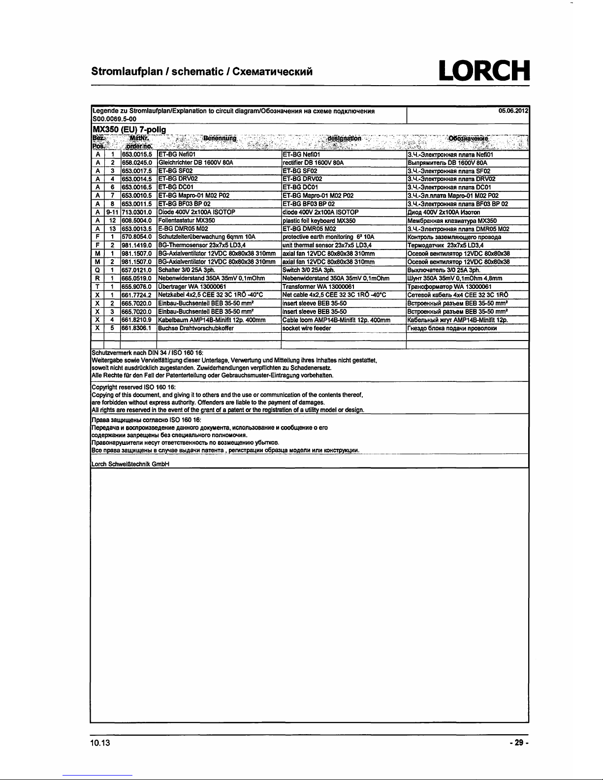
Stromlaufplan I schematic I
CxeMaTM'leCKMM
LORCH
Legende zu Stromlaufplan/Explanation to circuit
diagrarn106o3Ha1.1eHMS1
Ha
cxeMe
nOAK1110'leHMS1
S00.0069.5-00
05.06.2012
~
..
.
·;_i~~~~!l~!~.,·-:~;.:.:.·
-
-,-,:.:::·:~;~i::~~E:-~.~-,-_._·-·:~~f~~~trid~--~-
7
~.r.J
ET-BG
Nefi01
3.4.-3neKTpoHHaJI
nnaTa
Nefi01
A 2
658.0245.0
Gleichrichter
DB
1600V
BOA
rectifier
DB
1600V
BOA
Bblnp!IMMTenb
DB
1600V
BOA
A 3
653.0017.5
ET-BG
SF02
ET-BG
SF02
3.4.-3neKTpoHHaJI
nnara
SF02
A 4
653.0014.5
ET-BG
DRV02
ET-BG
DRV02
3.4.-3neKTpoHHaJI
Mam
DRV02
A 6
653.0016.5
ET-BG
DC01
ET-BG
DC01
3.4.-3neKTpoHHaJI
nnara
DC01
A 7
653.0010.5
ET-BG
Mapro-01
M02
P02
ET-BG
Mapro-01
M02
P02
3.4.-3n.nnara
Mapro-01
M02
P02
A B
653.0011.5
ET-BG
BF03
BP
02
ET-BG
BF03
BP
02
3.
4.-3neKTpoHH8JI
nnara
BF03
BP
02
A
9-11
713.0301.0
Diode400V
2x100A
ISOTOP
diode
400V
2x100A
ISOTOP
,QMO,Q,
400V
2x100A
1113oron
A
12
60B.5004.0
Folientastatur
MX350
I
plastic
foil
kevboard
MX350
MeM6paHHaJ1
K118BM8TYP8
MX350
A
13
653.0013.5
E-BG
DMR05
M02
ET-BG
OMR05
M02
3.
4.-3neKTPOHH8JI
nnam
DMR05
M02
F 1
570.B054.0
Schutzleiteriiberwachung
6qmm
10A
protective
earth
monitoring
6210A
F 2
9B1.1419.0
BG-Thermosensor
23x7x5
LD3,4
unit
thermal
sensor
23x7x5
LD3,4
M 1
9B1.1507.0
BG-Axialventilator
12VDC
80x80x38
310mm
axialfan
12VDC
80x80x3B
310mm
M 2
9B1.1507.0
BG-Axialventilator
12VDC
80x80x3B310mm
axial
fan
12VDC
80x80x38
310mm
Q 1
657.0121.0
Schalter
310
25A
3ph.
Switch
310
25A
3ph.
R 1
665.0519.0
Nebenwiderstand
350A
35mV
0,
1m0hm
Nebenwiderstand
350A
35mV
0, 1 mOhm
T 1
655.9076.0
Obertrager
WA
13000061
Transformer
WA
13000061
X 1
661.
7724.2
Netzkabel
4x2,5
CEE
32
3C 1 RO
-40°C
Net
cable
4x2,5
CEE
32
3C 1 RO
-40°C
X 2
665.
7020.0
Einbau-Buchsenteil
BEB
35-50
mm
2
insert
sleeve
BEB
35-50
X 3
665.
7020.0
Einbau-Buchsenteil
BEB
35-50
mm
2
insert
sleeve
BEB
35-50
X 4
661.8210.9
Kabelbaum
AMP14B-Minifrt
12p.
400mm
Cable
loom
AMP14B-Minifit
12p.
400mm
X 5
661.8306.1
Buchse
Orahtvorschubkoffer
socket
wire
feeder
Schutzvermerk
nach
DIN
34 / ISO
160
16:
Weitergabe
sowie
Vervielfliltigung
dieser
Unterlage,
Verwertung
und
Mitteilung
ihres
lnhaltes
nicht
gestattet,
soweit
nicht
ausdrocklich
zugestanden.
Zuwiderhandlungen
verpflichten
zu
Schadenersatz.
Alle
Rechte
tor
den
Fall
der
Patenterteilung
oder
Gebrauchsmuster-Eintragung
vorbehalten.
Copyright
reserved
ISO
160
16:
Copying
of
this
document,
and
giving
it
to
others
and
the
use
or
communication
of
the
contents
thereof,
are
forbidden
without
express
authority.
Offenders
are
liable
to
the
payment
of
damages.
All
rights
are
reserved
in
the
event
of
the
grant
of a
patent
or
the
registration
of a utility
model
or
design.
npaea
38~1®Hbl
cornaCHo
ISO
160
16:
nepe,Q,8"18 M eocnpoM3Be,Q,eHMe
ASHHOro
,Q,OK)'MeHT8,
McnOnb30B8HMe
M
coo6~eHMe
0
ero
CO,Q,ep>KaHMM
sanpe~eHbl
6e3
cneizyianbHOro
nonHOMCNMJI.
npasoHapywMTenM
HeCyr
OTBeTCTBeHHOCTb
no
B03Me~eHMIO
y6blTKOB.
Bee
npaea
38~111~eHb1
e
cnY'lae
eb1,qa11M
nareHTa , pemcrpa4MM
o6pm4a
Mo,qenM
MnM
KOHCTpVKUMM.
Lorch
SchweiBtechnik
GmbH
10.13
KoHTponb
383eMnJ110~ero
npoeo,qa
Tepuo,Q,&T4MK
23x7x5
LD3,4
OceaoM
BeHnmJITOp
12VDC
80x80x38
Oceam1
ee1m1nJ1TOp
12VDC
80x80x38
BblKltlO"laTenb
310
25A
3ph.
WYHT
350A
35mV
0,
1m0hm
4,Smm
TpaHC<f>OpMarop
WA
13000061
Cereaoi'I
Ka6enb
4x4
CEE
32
3C
1R0
BcrpoeHHblM
pa3beM
BEB
35-50
mm
2
BcrpoeHHblM
pa3beM
BEB
35-50
mm
2
Ka6enbHb1M
>Kryr
AMP14B-Minifrt
12p.
-29
-
Page 30
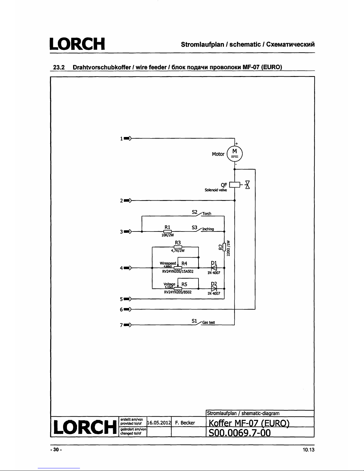
LORCH
Stromlaufplan I schematic I
CxeMaTM"leCKMM
23.2 Drahtvorschubkoffer I wire feeder I 6noK
noAa'IM
npoeonoKM MF-07 (EURO)
2•
52:T<Xth
I
Rl
3•)
[=:J
53
Inching
10K/2W
R3
~
~
4,7K/2W
c:
:Ta
N
WI~
R4
01
4•
RV24YN205/15A502
IN
4007
~ol~e
R5
02
RV24YN205/B502
IN
4007
S•
6•
7•)
51/Gastest
-
30-
10.13
Page 31

Anschl
ussbelegung/term
inalassignment/CxeMa KOHTaKToepaJbeMa
LQR
CH
24
Anschlussbelegung I terminal assignment I CxeMa
KOHTaKToe
pa3beMa
Steckverblndung
Drahtvorschubkoffer
7-polig
(Version
EU) I
connecting
socket
wire
feeder 7 pin
(version
EU) I
CoeAr.1Hr.1T
e11b
6noKa
noAa4r.1
npoeonoKr.1
7-KOHTaKTHblM
(eepcr.1s:1
EU)
Pos
1
2
3
4
5
6
~
10.13
Ansicht Stecker-u
nd
Buchsenseite
View
Plug and socket side
B
111A
co
cro
pOHbl
pa3beMa
111
rne3Aa
Bezelchnung
Motor
motor
5
designation
Magnetvent
il
so
lenoid valve
---
Brennertaster/Orahteinlauhaster
torch sw tch/wire insert swi
tc
h
Potentiometer
Schwei~pannung
potentiometer welding voltage
Potentiometer Drahtvorschub potentiometer wire
feed
GND GND
Gastest-Taster
gas test switch
)--
2 2 5
Ha3eaHi.te
Morop
MarHlffHbll::\
1U1anaH
KHonKa ropenK111/
KHOnKa
nporn>KKIA
nposo
noKM
noreH~HoMerp
ceapoYHoro HanpR>KeHL>iR
noreH~HOMerp
MOTopa
AJlR
npOT.RlKICl.1
npoeonoKL>I
3eMml
K1-1onKa-raaoab1i't
reCT
-
31
-
 Loading...