

EN
Operation Manual Page 17
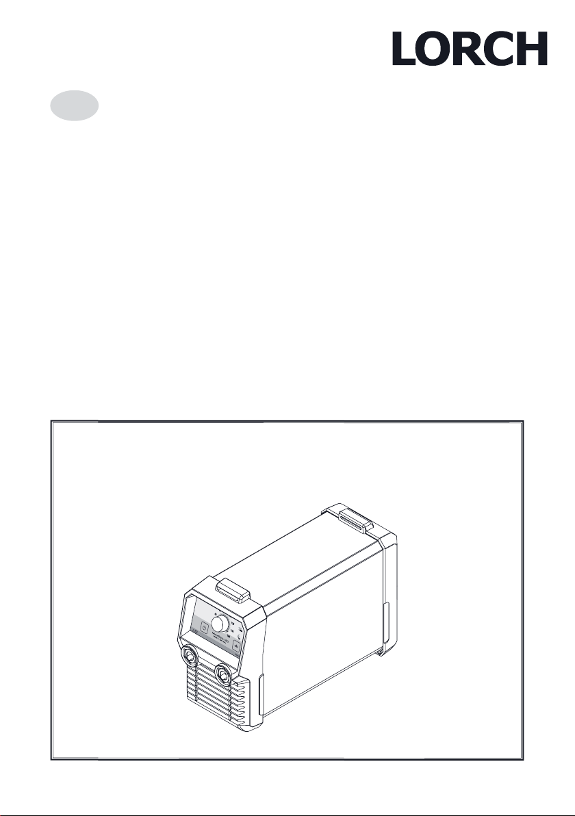
MicorStick
909.2049.9-00

IX
Easy Go 1
Order no. 570.7595.1
Easy Go 2
Order no. 570.7595.2
Easy Go 3
Order no. 570.7595.3
Weld Backpack
Order no. 570.7595.4
909.2049.9-00 - 2 -01.14

MicorStick + MobilePower
1 2
3 4
909.2049.9-00 - 3 -01.14

I
1
2
3
4
L1(R)
L
L
N(MP)
PE
- 4 -
7
5
II
6
53 545150
8
1
55
56
IV
2(S)
3
(T)
1
1
2
1
III
01.14909.2049.9-00

V VI
3
58
VII
18
10 11 12 13
61
60
62 63
66
64
65
14
15
1617
VIII
- 5 -
01.14909.2049.9-00

Publisher LORCH Schweißtechnik GmbH
Im Anwänder 24 - 26
D-71549 Auenwald
Telephone: +49 (0) 7191 / 503-0
Fax: +49 (0) 7191 / 503-199
Website: www.lorch.biz
Email: info@lorch.biz
Document number 909.2049.9-00
Issue date 08.01.2014
Copyright © 2013, LORCH Schweißtechnik GmbH
This documentation including all its parts is protected
by copyright. Any use or modication outside the strict
limits of the copyright law without the permission of
LORCH Schweißtechnik GmbH is prohibited and liable to
prosecution.
This particularly applies to reproductions, translations,
microlming and storage and processing in electronic
systems.
Technical changes Our machines are constantly being enhanced, we reserve
the right to make technical changes.
909.2049.9-00 - 17 -01.14

General regulation of use
1 Machine elements
1 Carrying belt
2 Control panel
3 Negative terminal socket
4 Positive terminal socket
5 Air intake
6 Mains cable
7 Power cable/battery cable with device coupling
(optional)
I
2 Explanation of symbols
2.1 Meaning of the symbols in the
operation manual
Danger to life and limb!
If the danger warnings are disregarded, this
can cause slight or severe injuries or even
death.
Danger of property damage!
Disregarding danger warnings can cause
damage to workpieces, tools, and equipment.
General note!
Indicates useful information about the prod-
i
uct and equipment.
Danger of death through electrocution!
See chapter “12.3 Connecting the power
supply” on Page 21.
Some of the options and accessories shown
or described may not be a part of the scope
of delivery.
i
Subject to change.
2.2 Meaning of the symbols on the
machine
Danger!
Read the user information in the operation
manual.
Disconnect the mains plug!
Pull out the mains plug before opening the
housing.
3 General regulation of use
This machine is intended for use in the commercial and
industrial sector. It is portable and suitable for operation
using the mains supply, a power generator or for operation with a battery (optional).
The machine is intended for electrode welding.
Together with a TIG welding torch, the machine can be
used for TIG welding with direct current of
– unalloyed steels, low and high-alloy steels,
– copper and its alloys,
– nickel and its alloys,
– special metals like titanium, zirconium, tantalum.
The device is not intended for TIG welding of aluminium and magnesium with alternating current.
- 18 - 01.14909.2049.9-00

Safety precautions
4 Safety precautions
Hazard-free working with the machine is only
possible if you read the operating and safety
instructions completely and strictly observe
them.
Please obtain practical training before using
the machine for the rst time. Follow the accident prevention regulations (UVV1).
Remove all solvents, degreasers, and other
ammable materials from the working area
before starting welding. Non-movable am-
mable materials must be covered. Only weld
if the ambient air contains no high concentrations of dust, acid vapours, gases or ammable substances. Special care must be
taken during repair work on pipe systems
and tanks which contain or have contained
ammable liquids or gases.
Never touch live parts inside or outside of the
housing.
Do not expose the machine to rain; do not
clean with sprays or steam jets.
Always use a protection shield when welding. Warn anyone in the work area about the
dangers of arc rays.
Please use a suitable extraction system for
gases and cutting vapours. Always wear
breathing apparatus whenever there is a risk
of inhaling welding or cutting fumes.
If the power cable is damaged or severed
while working, do not touch the cable, but immediately pull out the mains plug. Never use
a machine if the mains cable is damaged.
Keep a re extinguisher near the welding
area. Check the welding area for re after
welding (see UVV1)).
Never try to disassemble the pressure re-
ducer. Replace the pressure reducer if faulty.
The machine must be transported or set up
only on rm, level surfaces. The maximum
admissible angle of inclination for setting up
or transporting is 10°.
Service and repair work may only be carried out by a
trained electrician.
Ensure that there is good direct contact for the ground
cable immediately beside the weld point. Do not pass
the welding current through chains, ball bearings,
steel cables, grounding conductors, etc., as it could
cause these to melt.
Secure yourself and the welding machine when work-
ing in elevated or inclined areas.
The machine should be connected only to a properly
grounded mains supply. (Three-phase four-wire system with grounded neutral conductor or single phasethree-wire system with grounded neutral conductor)
socket and extension cable must have a functional
protective conductor.
Wear protective clothing, leather gloves and a leather
apron.
Protect the welding area with curtains or mobile
screens.
Do not use welding equipment to thaw out frozen wa-
ter pipes or lines.
In closed containers, under cramped conditions, and
in high electrical risk areas, only use machines with
the S sign.
When taking a break, switch off the machine and close
the valve on the gas cylinder.
Secure the gas cylinder with a chain to prevent it fall-
ing over.
Disconnect the mains plug from the mains before
changing the place of installation or making repairs to
the machine.
Please heed the safety regulations which apply to your
country. Subject to change.
1
Only applicable for Germany. Can be ordered from
Carl Heymanns-Verlag, Luxemburger Str. 449,
50939 Köln.
909.2049.9-00 - 19 -01.14

Electromagnetic compatibility (EMC)
5 Ambient conditions
Temperature range of ambient air:
in operation: -10 °C ... +40 °C (+14 °F to +104 °F)
transport and storage: -25 °C ... +55 °C
(-13 °F ... +131 °F)
Relative humidity:
up to 50 % at 40 °C (104 °F)
up to 90 % at 20 °C (68 °F)
Operation, storage and transport may only be
carries out within the ranges indicated! Use outside of this range is considered not used with
its intended purpose. The manufacturer is not
liable for damages cause by misuse.
Ambient air must be free of dust, acids, corrosive gases
or other damaging substances!
6 Unit protection
This machine is protected electronically against overloading. Do not use fuses of higher amperage than printed on
the identication plate.
The machine is cooled using a fan.
Therefore, always ensure that the cooling air openings
are always uncovered.
Do not insert any objects into the ventilation slots. This
may damage the fan.
Never perform a welding operation when the fan is de-
fective. Instead, have the device repaired.
Switch-on duration (ED)
The switch-on duration (ED) is based on a work cycle of
10 minutes. ED 60% therefore means a welding duration of 6 minutes. After this, the device must cool down
for 4 minutes.
If the ED is exceeded then an integrated thermocouple
switches the machine off. When the device has cooled
down sufciently, it switches itself back on.
7 Noise emission
The noise level of the unit is less than 70 dB(A), measured under standard load in accordance with EN 609741 in the maximum working point.
8 UVV inspection
Operators of commercially-operated welding systems are
obliged to have regular safety inspections of the equipment
carried out in accordance with EN 60974-4. Lorch recommends inspections at 12 month intervals.
A safety inspection must also be carried out if modications or repairs have been made to the system.
Improper UVV inspections can destroy the
system. For more information on UVV inspections of welding systems, please contact
your authorised Lorch service centre.
9 Electromagnetic
compatibility (EMC)
This product is manufactured in conformance with the
current EMC standard. Please note the following:
Due to their high power consumption, welding ma-
chines can cause problems in the public power grid.
The mains connection is therefore subject to requirements with regard to the maximum permissible system impedance. The maximum permissible system
impedance (Zmax) of the interface to the power grid
(mains connection) is indicated in the technical data.
If in doubt, please contact your power grid operator.
The machine is intended for welding in both commer-
cial and industrial applications (CISPR 11 class A).
Use in other surroundings (for example in residential
areas) may disturb other electronic devices.
Electromagnetic problems during start-up can arise in:
– mains cables, control cables, signal and telecom-
munication lines near the welding or cutting ma-
chine
– TV/radio transmitters/receivers
– Computers and other control devices
– Protection equipment such as alarm systems
– Pacemakers and hearing aids
– Measurement and calibration devices
– Equipment with too little protection against interfer-
ence
If other equipment is disturbed, it may be necessary to
provide additional shielding.
The affected area may go beyond the boundaries of
the property concerned. This depends on the layout
of the building, and the other activities that may be
going on there.
Please use the machine in compliance with the manufacturer's instructions. The operator of the equipment is
responsible for the installation and use of the machine.
The owner is responsible for eliminating the interference
- 20 - 01.14909.2049.9-00

Before start-up
caused by electromagnetic elds (possibly with technical
assistance by the manufacturer).
10 Setup and transport
Danger of injury due to the device falling
over and crashing.
Before transport, disconnect the mains plug.
Carry the device using the transportation belt
and keep it in a horizontal position.
Do not use a fork-lift truck or similar device to
lift the machine by its housing or transportation belt.
The machine must be set up only on rm,
level and dry surfaces. The maximum admissible angle of inclination for setting up is 10°.
Therefore, always ensure that the cooling air
openings are always uncovered.
– Do not set up the device directly by a wall.
– Do not cover any cooling air openings.
The device may overheat and be damaged.
Cooling air openings are located on the
– Front side of the housing
– Rear side of the housing
11 Brief operating instructions
 Connect the mains or battery cable.
 Connect the component guide and electrode holder to the
sockets 3 and 4.
Observe the polarity according to the data of
the electrode manufacturer (see also electrode welding).
i
 Tension the stick electrode on the electrode holder.
 Switch the machine on by pressing the On/Off button
17 for 2 sec..
 Select the desired electrode operating mode using the
16 button.
 Set the desired welding current using the rotary knob
12.
9 The machine is now ready for welding.
12 Before start-up
12.1 Fastening the transportation
II
belt
 Thread the transportation belt 1 into the welding ma-
chine and plastic slides 8. See sequence of the numbering in the picture.
12.2 Connecting the ground cable
When selecting the working space, ensure that the
ground cable and the ground clamp can be fastened
properly.
The ground clip must be fastened to an exposed
location of the welding table or component, so that it is
highly conductive. It must be located in the immediate
vicinity of the welding area, so that the welding current
cannot seek its own return path across machine parts,
ball bearings or electric circuitry.
Do not place the ground clamp on the welding machine, as otherwise the welding current will be carried
via the protective conductors and it will destroy these.
Never attach the workpiece connection loosely. Connect
the ground clamp rmly to the welding bench or the
workpiece.
12.3 Connecting the power supply
Mains cable with device coupling
Danger of death through electrocution!
If the plug-in mains cable is used incorrectly when humidity or moisture is present, particularly outdoors, then electrocution is possible.
When working in mains operation, observe the following:
First, connect the mains cable to the machine coupling on the welding machine
and then connect the mains cable to the
mains plug in the mains socket.
Always disconnect the mains plug from
the mains socket before disconnecting
the machine coupling.
Mains operation
Before commissioning the machine, ensure that a suitable mains connection is available. The fuse must meet
the requirements stated in the technical data.
III
909.2049.9-00 - 21 -01.14

Before start-up
 Connect the mains cable.
9 The device is in standby mode.
Battery operation (optional)
For mobile use, the machine can be used in battery operation with a Lorch MobilePower battery pack.
 Connect the battery cable.
9 The device is switched on.
When working with battery operation, observe the following:
i
First, connect the battery cable to the machine coupling on the welding machine and
then switch the MobilePower battery pack on.
Always switch the MobilePower battery pack
off before disconnecting the device coupling of
the battery cable.
Never disconnect the battery cable when operating the welding machine.
Generator operation
Alternatively, the machine can be connected to a power
generator. Please note:
– If you want to use the full power range of the weld-
ing equipment, the output power of the generator
must at least match the input power of the welding
equipment (see Technical Data).
– If the generator is overloaded, then arc pulsing or
an arc breakaway is possible.
Mains extension cables
Only use intact mains extension cables which offer the
specied protection.
Coiled cables may heat up considerably. Always un-
wind extension cables fully.
When particularly long mains extension cables are used,
the mains voltage on the machine may fall to such an extent that the welding power falls. Shorten the extensions
and/or use extensions with a larger cable cross-section.
12.4 Electrode welding process
Connecting the electrode cable
Connect the electrode welding cable to the negative 3
or positive 4 socket and secure the cable by rotating it
clockwise.
Note the manufacturer's information when
selecting a suitable stick electrode. The
i
electrode diameter is dependent upon the
thickness of the material to be welded.
Electrode welding with positive (+) electrode:
 Connect the electrode holder to the positive terminal
4 of the machine and secure it by turning the plug to
the right.
Electrode welding with negative (-) electrode:
 Connect the electrode holder to the negative terminal
3 of the machine and secure it by turning the plug to
the right.
 Push the lever on the handle of the electrode holder.
Clamp an electrode with the exposed end in the holder. Note the notches on the inner side of the two jaws.
12.5 TIG welding process
For TIG welding you require a TIG valve
torch (Type LTV 1700) for this machine.
i
Installing electrodes
 Unscrew the clamping cap 55.
 Remove the electrode 54 from the collet 53.
 Grind the end of the electrode 54.
 Slide the electrode 54 into the collet 53.
 Insert the electrode 54 into the torch and rmly tighten
the clamping cap 55.
Do not dismantle the collet body 51 and the
gas nozzle 50.
IV
i
When converting the torch to a different electrode diameter, please pay attention to the
following.
The collet 53, collet body 51 and electrode 54 must
have the same diameter.
The gas nozzle 50 must be matched to the electrode
diameter.
Connecting the TIG torch
 Connect the TIG torch 58 to the negative terminal 3
and secure it by turning it to the right.
Connecting the inert gas cylinder
 Secure the inert gas cylinder 60, e.g. by using a secur-
ing chain.
V
VI
- 22 - 01.14909.2049.9-00

Commissioning
 Briey open the gas cylinder valve 61 several times
in order to blow out any dirt particles that are present.
 Connect the pressure reducer 64 to the inert gas cyl-
inder 60.
 Screw the inert gas hose 65 to pressure reducer 64 and
open the gas cylinder valve 61.
 Open the gas valve 56 on the TIG welding torch.
9 Inert gas ows out.
 Adjust the volume of gas using the setting screw 66.
9 The gas ow rate is indicated on the ow meter 63.
Rule of thumb:
Gas nozzle size = litres/min.
The cylinder content is indicated on the content ma-
nometer 62.
13 Control panel
10 LED fault
Lights up continuously when the system has over-
heated or ashes if there is a fault (see Chapter
Messages), no arc ignition possible.
11 LED VRD (only for machines with VRD) lit contin-
uously when the VRD function is active (reduction
of idle voltage). Flashes when the output voltage
exceeds the value approved in the standard (e.g.
in welding operation).
12 Rotary knob, welding current
For innite adjustment of the welding current.
13 LED CEL electrode
Lights up with operating mode Electrode CEL
selected (Electrodes with
cellulose-containing encapsulation, suitable for
vertical downward welding).
14 LED electrode
Lights up when Electrode operating mode selected.
15 LED TIG
Lights if TIG operating mode is selected.
16 Electrode/TIG button
Selects the operating mode.
17 On/Off button (2 sec.)
Switches the device on or into Standby mode.
VII
18 LED On
Lights up when switched on
ashes every 3 sec. in Standby mode
After the system is connected,
– all the displays light up for 2 sec. as a self-test.
– The most recently set operating mode is selected.
14 Commissioning
14.1 Energy-saving function
Welding machine energy-saving function
If the welding machine has been connected to the mains
power or generator, then the energy-saving function of
the welding machine is active.
When the mains plug has been connected, the ma-
chine is in Standby mode and the On LED 18 ashes
every 3 sec.
If the device is in Standby mode, then it can be
switched on using the On/Off button 17.
If the device is switched on, then it can be switched to
Standby mode using the On/Off button 17.
If the device is not used for 30 min., then it automati-
cally switches to Standby mode.
Energy-saving function using battery
pack
If the welding machine is connected to a MobilePower
battery pack, then the energy-saving function of the battery pack is active and the energy-saving function of the
welding machine is deactivated.
When the welding machine is connected to the bat-
tery pack and the battery pack is switched on, then the
welding machine is always switched on.
If the welding device is not used for some time, then
the battery pack will switch to Standby mode automatically and switch the welding machine off.
Refer to the MobilePower 1 operating manual.
Before switch-on, ensure that neither the
electrode holder nor the electrode is touching
the welding table, the workpiece or another
electrically-conductive object, to ensure that
you do not unintentionally ignite arcing on
switch-on. An unintentionally ignited arc can
damage the electrode holder, the welding table, the workpiece and the machine.
909.2049.9-00 - 23 -01.14

Commissioning
14.2 Electrode welding process
Switch on the system
 If necessary, switch the system on by pressing button
17 for 2 sec.
 Keep pressing button 16 until the electrode operating
function is selected.
9 The electrode icon MMA or CEL (LED 13 or 14) lights
up.
 Use control knob 12 to set the desired welding current.
Arc ignition
 Briey touch the workpiece at the point to be welded
using the electrode and lift the electrode a little.
9 The arc burns between the workpiece and the elec-
trode.
Hotstart
In the electrode welding method, a hotstart of 125 %
of the set welding current is used for 1 second for ignition. Like the welding current, the hotstart is limited to
a maximum of 150 A.
Guide values for current intensity
Electrode Ø
[mm]
1.5 20...40
2.0 35...60
2.5 45...100
3.2 75...140
4.0 130...190
Recommended current
intensity [A]
 Briey touch the workpiece with the tip of the elec-
trode at the point to be welded.
 Lift the electrode a little.
9 The arc burns between the workpiece and the elec-
trode.
Upslope
A short-circuit current of 60 A is used for igniting during
the TIG welding process. The upslope takes place with
115 A/s until the set welding current is reached.
Guideline values for the current intensity
and the gas quantity
Tungsten electrodes Ø [mm]
1.0 15...80 4
1.6 70...150 5...6
2.4 150...250 6...7
Current inten-
sity [A]
Gas quantity
[l/min]
14.3 TIG welding process
Switch on the system
 If necessary, switch the system on by pressing button
17 for 2 sec.
 Keep pressing button 16 until the TIG operating func-
tion is selected.
9 The TIG icon (LED 15) lights up.
 Use control knob 12 to set the desired welding current.
Arc ignition
 Open the valve 56 on the TIG welding torch.
VIII
- 24 - 01.14909.2049.9-00

Messages
15 Technical data
Technical data Units
MicorStick
Welding
TIG welding area (I
I
2max/U2min-U2max
Electrode welding area
(I
2min-I2max/U2min-U2max
-
2min
)
A/V
A/V
)
15...160/
10,6...16,4
10...150/
20,4...26,0
Idle voltage, max. V < 113
Power setting
innitely
variable
Slope characteristic falling
Welding current at ED 100%
Welding current at ED 60%
A 110
A 120
ED at max. current % 30
Mains
Mains voltage (50/60 Hz)
V 230/1~
Positive mains tolerance % 15
Negative mains toler-
ance
Input power S1
(100%/40°C)
Input power S1
(60%/40°C)
Input power S1 (max.
current)
Current input I1
(100%/40°C)
Current input I1
(60%/40°C)
% 15
kVA 3,3
kVA 3,6
kVA 5,2
A 14,2
A 15,6
160
Technical data Units
Current input I1 (max.
Strom)
Power factor cos φ (for
I
)
2 max.
A 22,5
MicorStick
0,99
Power factor λ for I2 max 0,97
Max. permissible system impedance Zmax
in acc. with IEC 61000-
mΩ 321
3-11/12
Mains fuse A/tr 16
Mains connection mm² 3x 2,5
Mains plug Schuko
Machine
Protection class (EN
60529)
IP 23S
Insulation class F
Cooling method F
Noise emission dB(A) < 70
Designation CE, S
Dimensions and weights
Dimensions (LxWxH) mm
360 x 130
x 215
Weight MicorStick 160 kg 4,9
Weight MicorStick 160
Accu-ready
*) measured at 40° C environmental temperature
kg 4,2
ED = Switch-on duration
160
16 Messages
Fault Possible cause Rectication
Fault LED 10
ashes
Fault LED 10 lit
continuously
Machine error Switch the machine off. When all the displays have gone
out, leave the system switched off for at least 1 minute.
Switch the system on again. If the fault persists, contact
the Service department.
ED exceeded,
Let the machine cool down whilst switched on
machine has overheated
909.2049.9-00 - 25 -01.14

Troubleshooting
17 Troubleshooting
Fault Possible cause Rectication
Displays remain
dark
No welding current
Arc does not
ignite
No inert gas Gas cylinder empty Replace gas cylinder
Too little inert gas Torch not tight Check and replace if necessary
Pores in weld
metal
Seam "cooking"
(unsteady arc)
TIG electrode
melting
Defective mains fuse Replace the fuse
Neutral conductor, mains phase
missing
Battery discharged Check and charge/replace battery
Ground line not connected or defec-
tive
Electrode holder or torch not con-
nected or defective
No or poor ground contact Ensure ground contact
Incorrect electrode diameter Select correct electrode diameter
Welding current set too low Set welding current higher
Tungsten electrode soiled or incor-
rectly ground
Gas volume set incorrectly Set gas volume correctly
Pressure reducer defective Check and replace if necessary
Gas valve on torch not opened or
defective
Gas hose not tight Tighten gas hose
Pressure reducer set incorrectly or
defective
Torch not tight Check and replace if necessary
Gas nozzle not tight Tighten gas nozzle
Torch head faulty Check and replace if necessary
Workpiece soiled with grease, rust,
oil, etc.
Draught Shield workplace
Gas supply missing Check
Incorrect gas Use correct gas
Welding current set too high for
electrode diameter
Polarity reversed and TIG torch con-
nected to positive terminal 4
Check mains cable / mains extension
cable
Check ground line and replace if necessary
Check electrode holder or torch and
replace if necessary
Grind correctly or replace the electrode
if necessary
Check and replace if necessary
Check and replace if necessary
Clean it
Set the correct welding current
Connect the TIG torch to the negative
terminal 3
- 26 - 01.14909.2049.9-00

Declaration of conformity
18 Accessories
See gures
IX
19 Maintenance and repair
Please heed the current safety and accident prevention regulations during all
maintenance and repair work.
The machine requires a minimum of care and maintenance. Only a few items need to be checked to ensure
trouble-free long-term operation.
19.1 Check regularly
Check the following points for damage before starting
up the welding machine:
– Mains plug and cable
– Welding torch and connections
– Ground cable and connection
– Keyboard membrane and control panel
Blow the welding machine out once or twice a year.
 To do this, switch the device and disconnect the mains
plug.
 Using dry compressed air, blow the welding machine
out from the front through the ventilation slots. Leave
the housing closed.
Never blow the compressed air through the
ventilation holes on the rear side of the machine. The fan is located there and the compressed air would make it turn so quickly that
bearing damage may result.
20 Disposal
Only for EU countries.
Do not dispose of electric tools together with
household waste material!
In observance of European Directive 2002/96/EC on
waste, electrical and electronic equipment and its implementation in accordance with national law, electric tools
that have reached the end of their service life must be
collected separately and returned to an environmentally
compatible recycling facility.
21 Service
Lorch Schweißtechnik GmbH
Im Anwänder 24 - 26
D-71547 Auenwald
Germany
Tel. +49 (0)7191 503-0
Fax +49(0)7191 503-199
22 Declaration of conformity
We herewith declare that this product was manufactured
in conformance with the following standards or ofcial
documents: EN 60 974, EN 61 000-3-2, EN 61 000-3-3
in conformance with the guidelines 2006/95/EC,
2004/108/EC, 2011/65/EU.
2013
Wolfgang Grüb
Managing Director
Lorch Schweißtechnik GmbH
909.2049.9-00 - 27 -01.14

Ersatzteilliste/Schaltplan / spare parts list/schematic / Список деталей/Схематический
MicorStick
160/160 Accu-ready990.4477.3-00
X
Gültigkeit / Validity / действительность
Type Serial no. from Serial no. to Variante
MicorStick 160 2009-0000-0000-0 2009-9999-9999-9 A
MicorStick 160 Accu-ready 2013-0000-0000-0 2013-9999-9999-9 B
9
8
10
7
2
11
7
19
23
3
24
18
6
16
4
12
15
21
20
13
14
22
1
17
5

909.2049.9-00
- 117 -01.14

Ersatzteilliste/Schaltplan / spare parts list/schematic / Список деталей/Схематический
N L1 PE
X1
A
X11/1
A1
MicorStick
C
B
X11/3
X11/4
160/160 Accu-ready990.4477.3-00
N L1 PE
X5
431
X4
1 2
3 4
A
C
B
X11/2
X2/1
X2/1
X2/2
X
X6
Akku-
Control
Akku+
PE
431 2
X4
1 2 3 4
A
C
B
A2
X2/1
M
M1
X2
-
X3
+
erstellt am/von
provided to/of
geändert am/von
changed to/of
Stromlaufplan / shematic-diagram
MicorStick 160 /MicorStick Accu-Ready
990.4477.3-00

Ersatzteilliste/Schaltplan / spare parts list/schematic / Список деталей/Схематический
MicorStick
ET/
SP/SCVariante/
X2
X3
variant
A
B
A
B
A
B
A
B
A
B
A
B
A
B
A
B
A
B
A
B
A
B
A
B
A
B
A
B
A
B
SPL
1 A 600.5893.0
2
3 B 602.3202.0
4
5 A 604.3211.0
6 B 604.3211.1
7
8
9
10
11
12
13
14
15
16 A2
17 X1 A 661.7513.3
18 X5 B 661.7513.8
19 X4 B 661.8951.0
20
21 A1
22 M1
23 B 665.2229.0 Abdeckkappe UTL IP67 cover cap UTL IP67
24 X6 B 570.7501.0 MobilePower 1 MobilePower 1 MobilePower 1
24 X6 B 990.4477.4 ET MobilePower 1
Mat.Nr. Bezeichnung designation Название
602.3200.0
981.3210.0 ET-Set Kunststofffront G32
604.3212.0 Griffaufnahme G32 handle mount G32 Держатель рукоятки G32
604.3612.0
604.3641.0
604.3744.0
606.2027.0
608.0884.0
610.3060.0
610.3061.0
614.0301.0
650.5587.5 E-Baugruppe BF16 (E) Pc-board BF16 (E)
665.7021.0
981.8124.0
981.1456.1
160/160 Accu-ready990.4477.3-00
Kreuzschlitzlinsenschr.
5,0x25 sw. verz.
U-Haube G32 RAL2002
GS-G
Anschlussblech Heck G32
Akku RAL9005
Kunststoffheck G32 RAL
9005
Kunststoffheck G32 RAL
9005 Blecheinsatz
Tragegurt 30x1500
Schwarz
Kunststoffschieber für Tragegurt 30mm
Handgriffrohr Alu 254mm
LORCH-Prol
Aufkleber Netzstecker
ziehen 30mm blau
Frontfolie MicorStick 160
CEL
Schaumstoffeinlage
108x105x15
Schaumstoffeinlage
119,5x108x15
Drehknopf 21mm schwarz/
Str. Deckel 6mm-D
Netzkabel MS 3x2,5 Schuko 3FS 3,2m
Netzkabel 4Gx2,5 Schuko
/ UTL
Kabelbaum UTL-Einbaustecker
Einbaubuchse 25-50 mm²
ST13 MS
ET-Set Leistungsbausatz
Micor-Stick 160
BG-Axialventilator MicorStick 12V DC
X
cross recessed screw
5,0x25 sw.
U-housing G18 - 3 RAL
2002 GS-G
Joint plate rear G32 Accu
RAL9005
spare parts-set plastic front
bottom G32
plastic backplane G32 RAL
9005
plastic backplane G32 RAL
9005 insert plate
transportation belt 30x1500
black
slide for transportation belt
30mm
handle tube Alu 254mm
LORCH-Prol
sticker pull mains plug 30
mm blue
front foil MicorStick 160
CEL
foam inset 108x105x15 Вставка 108x105x15
foam inset 119,5x108x15 Вставка 119,5x108x15
knob 21mm black/ind. mark
knob cap 6mm-D
mains cable MS 3x2,5
Schuko 3FS 3,2m
mains cable 4Gx2,5 Schuko / UTL
Cable loom UTL insert plug
insert sleeve 25-50 mm²
ST13 MS
spare parts-set power unit
MicorStick 160
axial fan 12V DC
spare parts list
MobilePower 1
Крестообразный винт
5,0x25 sw. оцинкованный
Крышка U-формы G18 -3
RAL 2002 GS-G
Соед.пластина сзади
G32 Батарея RAL9005
З.Ч. Передняя часть
пластмассовая G32
Задняя часть пластмассовая G32 RAL 9005
Передняя часть пластмассовая G32 RAL 9005
Ремень для переноски
30x1500 чер.
Пластмассовый ползунок
30mm
Рукоятка Aлю 254мм
LORCH-Профиль
Наклейка Вытащить вилку 30mm синяя
Передняя пленка
MicorStick 160 CEL
Ручка вр. 21mm чер.с мет.
кр. 6mm
Электронная плата BF16
(E)
Сетевой кабель MS 3x2,5
Сетевой кабель 4Gx2,5
Кабельный жгут UTLВстроенная вилка
Встроенный разъем 25-50
mm² ST13 MS
Силовой модуль
MicorStick 160
З.Ч. вентилятор MicorStick
12V DC
Крышка защитная UTL IP67
Список деталей
MobilePower 1
(E) Ersatzteil / spare part / Запасные части
(T) Tauschteil / replacement part / Обменные части

Lorch Schweißtechnik GmbH Im Anwänder 24 - 26 D-71549 Auenwald Germany
Tel. +49 (0)7191 503-0 Fax +49 (0)7191 503-199 info@lorch.biz www.lorch.biz
 Loading...