


1
Loop-O9500
SDH/SONET IMAP
Features
• 6U height, full front access (ETSI) shelf
• TM, ADM and DCS (full cross-connect) at DS0,
VC11, VC12, VC3, VC4
• Dual STM-1/4 (OC-3/12) Optical Ring Uplinks
• Hot-swappable cross-connect modules,
tributary modules and power modules.
• Tributary Modules (See Table 1 below)
- High-Speed (aka High Density) access
tributary modules (HS)
- Low-Speed access tributary modules (LS)
• Power Modules
- DC Module (-48Vdc)
- Dual Power (1+1) Protection
• Protection Scheme
y Tributary protection
- E1/T1: card, port, line
- E3/T3: line
- B155/622: MSP, SNCP/UPSR
- Ethernet
- 7 FOM: line
y Cross-connect Unit (XCU) protection
- MSP
- SNCP/UPSR
• External/Internal/Line timing source with SSM
• Ethernet supports GFP, LAPS, VCAT, LCAS
and non-LCAS
• Full switched Ethernet capability on EoS with
built-in L2 switch card
• Ethernet Order Wire (EOW) using VoIP
technology
• Alarm suppression, masking and reports
• Management
• Console port, VT100 menu-driven
• SNMP Port
• Telnet
• Centralized management with Loop’s EMS/iNMS
over DCC channel
• LoopView GUI EMS
• TMN management(Loop-iNMS) with full FCAPS
and end-to-end circuit management
• SSH
•
RoHS compliant
Description
The Loop-O9500 SDH/SONET IMAP (Integrated
Multi-Services Access Platform) is an economical STM-1/4
(OC-3/12) access multiplexer designed to provide
integrated access to STM-1/4 (OC-3/12) optical lines.
Access is provided through either a non-blocking
VC11/VC12/VC3/VC4 cross-connect with HS modules or
through an additional non-blocking DS0 cross-connect
fabric with LS modules.
The 6U shelf supports:
• 4 HS tributary module slots
• 6 LS tributary module slots
With up to 10 optical STM-1 (OC-3) or 5 optical STM-4
(OC-12) or 10 electrical STM-1 (OC-3) line interfaces, the
Loop-O9500 SDH/SONET IMAP offers service providers a
versatile protection schemes including SNCP(UPSR) and
MSP(1+1) protection for both ring and linear network
topologies. The O9500 can work with the Loop-O9100 and
Loop-O9400 in the same topology.
The non-blocking VC11/VC12/VC3/VC4 cross-connect
capability on High Speed (HS) is up to 20 VC4. The HS
tributary modules include optical STM-1/4 (OC-3/12),
E3/T3, E1/T1 interfaces and Fast Ethernet over STM-1/4
(OC-3/12). Fast Ethernet signals are mapped onto STM
payload through standard techniques GFP, LAPS, VCAT,
LCAS, and non-LCAS. These HS modules are identical to
those used in the rack version of the Loop-O9400.
The uplink non-blocking DS0 cross-connect to HS is up to
21 E1 or 28 T1. The non-blocking DS0 cross-connect
capability on Low Speed (LS) is up to 768 DS0. Through a
full non-blocking DS0 cross-connect and together can act
as a mini DACS. The modules include variety of TDM, IP,
and voice interfaces detailed on next page. All LS modules
are identical to those used in rack version of the
Loop-AM3440.
All interfaces are fully compliant with the relevant ETSI
standards and ITU recommendations. The O9500
SDH/SONET IMAP provides full Operation, Administration,
Maintenance and Provisioning (OAM&P) functionality.
Users can easily operate the O9500 locally or remotely for
centralized management with LoopView (EMS) and
Loop-iNMS (integrated NMS)
.

2
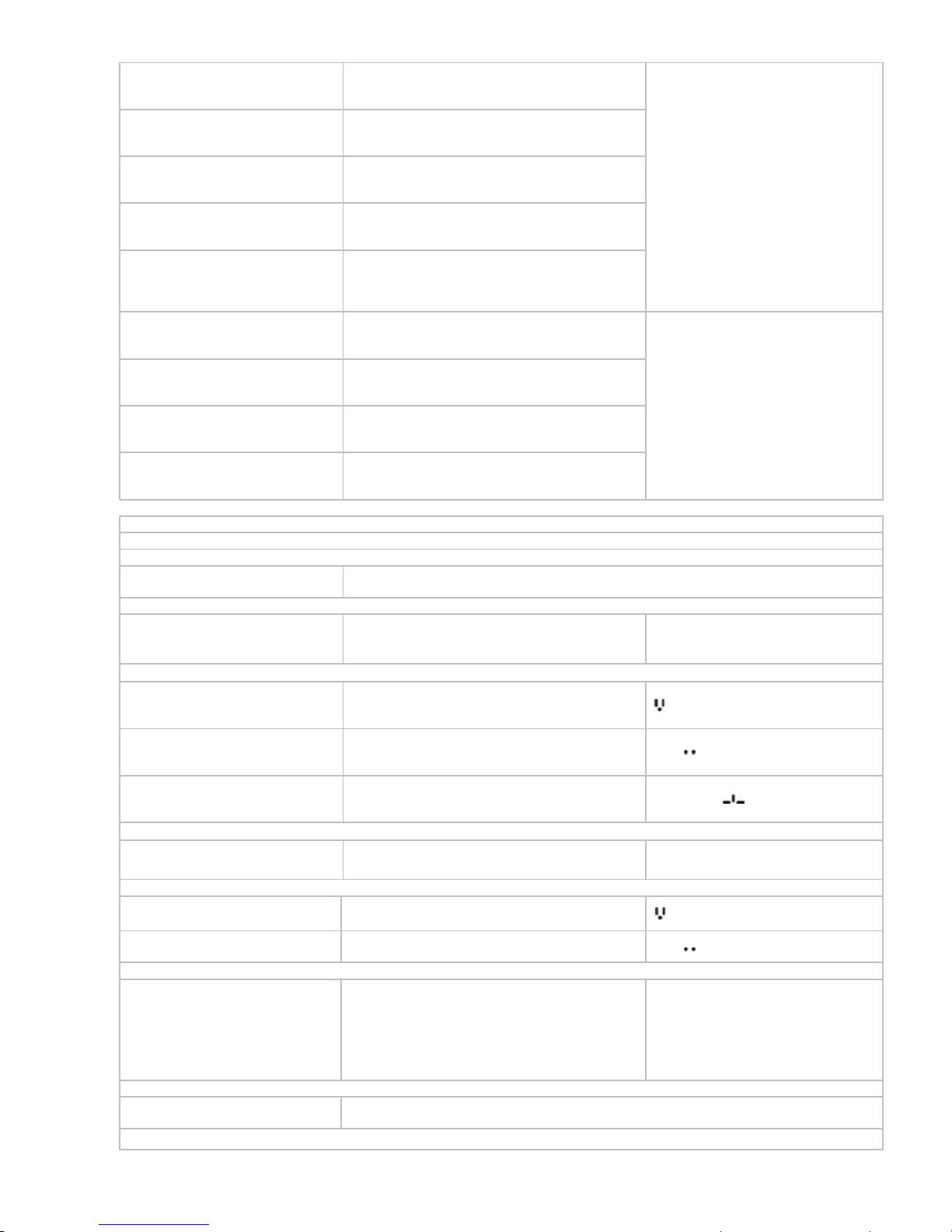
Table 1 Loop-O9500 Tributary Modules:
Tributary Type Plug-in Interface Cards Maximum Capacity
STM-4 (OC-12) tributaries 1 MSP 1 + 1
STM-1 (OC-3) tributaries 4 MSP 1 + 1 or 3 Sub-ring SNCP or 6 STM-1
without protection
63 port E1/T1 tributaries
32 port E1/T1 tributaries
16 port E1/T1 tributaries
252 E1/T1 without protection, or 126 E1/T1
with 1+1 card protection
3 port E3/T3 tributaries 12 E3/T3 without protection, or 6 E3/T3 with
1+1 card protection
EoS (8FE+1GbE) Ethernet card with
built-in L2 switch
4 GbE + 32 FE
EoS (8FE or 1GbE) Ethernet card without
L2 switch
4 GbE or 32 FE
High-Speed or High
Density Access
Tributary Modules
(HS)
7 port FOM tributaries 28 FOM without protection, or 14 FOM with
protection
Low Speed Single-Slot Cards
8-port Bridge/Router 48-port Bridge/Router
4-channel E1/T1 24/24-channel E1/T1
3-channel E1* 18-channel E1*
2-channel G.SHDSL (2 pairs) without line
power
12 channel G.SHDSL (2 pairs) without line
power
4-channel G.SHDSL (1 pairs) without line
power
24 channel G.SHDSL (1 pairs) without line
power
8-channel G.703 card at 64 Kbps data rate 48-channel G.703 card at 64 Kbps data rate
1 or 4 channel C37.94 (low speed optical) 6 or 24 channel C37.94 (low speed optical)
8-channel RS232/V.24 48-channel RS232/V.24
8-channel Dry Contact I/O 48-channel Dry Contact I/O
8-channel Dry Contact I/O type B 48-channel Dry Contact I/O type B
8-channel 2W/4W E&M 48 channel 2W/4W E&M
12-channel FXS 72 channel FXS
12-channel FXO 72 channel FXO
Conference card * Conference card *
12-channel Magneto 72-channel Magneto
TDMoE TDMoE
Low Speed Dual-Slot Cards
6-channel V.35 18-channel V.35
6-channel V.36 18-channel V.36
6-channel X.21/V.11 18-channel X.21/V.11
6-channel EIA530/RS449 18-channel EIA530/RS449
24-channel FXS 72-channel FXS
Low-Speed Access
Tributary Modules
(LS)
24-channel FXO 72-channel FXO
Note: * Future Option
Single-Slot Cards plug into singles slots; Dual-Slot Cards plug into two adjacent single slots

3
Table 2: Maximum number of channel/port on each plug-in card
Slot
Plug-in Card
TRIB 1 TRIB 2 TRIB 3 TRIB 4 XCU 1 XCU 2 11~16 slot/
per card
Total
For HS slots
63 63 63 63 x x x
252
E1/T1
E1/T1
For LS slots
x x x x x x
4E1
4T1
21E1
24T1
FE
8 8 8 8 x x x 32
Ethernet
GbE
1 1 1 1 x x x 4
STM-1
2 2 2 2(B) 2 2 x 8
Optical
(SFP)
STM-4
1 1(B) x x 2 2 x 4
E3/T3
3 3 3 3 x x x 12
7 FOM
7 7 7 7 x x x 28
Bridge/Router x x x x x x 8 48
G.SHDSL x x x x x x 2/4 12/24
3 E1* x x x x x x 3 18
G.703 x x x x x x 8 48
C37.94 x x x x x x 1/4 4/24
Dry Contact x x x x x x 8 48
Dry Contact type B x x x x x x 8 48
RS232/V.24 x x x x x x 8 48
Conference*
(Note 1) x x x x x x 6 36
12 FXS/FXO x x x x x x 12 72
12 Magneto x x x x x x 12 72
E&M x x x x x x 8 48
V.35/V.36/X.21 x x x x x x 6 18
EIA530/RS449 x x x x x x 6 18
24 FXS/FXO x x x x x x 24 72
TDMoE x x x x x x 4 24
* Future Option
X: not applicable
(B) Backup
Note 1: A c
onference plug-in card contains two RS232 data ports, two FXS ports and two E&M ports.

4
Ordering Information
To order specify:
Note: RoHS compliant units are identified by the letter G appearing immediately at the end of the ordering code.
Model Description Note
Main Unit
Loop-O9500-R-CHA-G
6U height Rack chassis for O9500 w/o CPU and
power
Plug-in modules
Loop-O9500-R-CC4-G
CPU card with cross-connect unit and two
STM-1/4 (OC-3/12) interfaces without SFP
(mini-GBIC) optical modules
One required for each chassis.
Order two for redundancy.
Loop-O9500-R-CBA-G
Connector Board
One required for each chassis.
Loop-O9500-R-CBB-G
Connector Board with EoW using VoIP
technology
One required for each chassis.
Loop-O9500-R-FANA-G
Fan Board
One required for each chassis.
High Speed or High Density Tributary Modules
Loop-O9500-R-16TE-G
16 E1 (120 ohm) or 16 T1 software
programmable plug-in card
This card can also be used in the
Loop-O9400R.
Loop-O9500-R-32TE-G
32 E1 (120 ohm) or 32 T1 software
programmable plug-in card
This card can also be used in the
Loop-O9400R.
Loop-O9500-R-63TE-G
63 E1 (120 ohm) or 63 T1 software
programmable plug-in card
This card can also be used in the
Loop-O9400R.
Loop-O9500-R-16E75-G
16 E1(75 ohm) plug-in card
Order two for redundancy.
This card can also be used in the
Loop-O9400R.
Loop-O9500-R-32E75-G
32 E1(75 ohm) plug-in card
Order two for redundancy.
This card can also be used in the
Loop-O9400R.
Loop-O9500-R-63E75-G
63 E1(75 ohm) plug-in card
Order two for redundancy.
This card can also be used in the
Loop-O9400R.
Loop-O9500-R-B16-G
STM-1/4 (OC-3/12) software configurable p
lug-in card without SFP (mini-GBIC) optical
modules
This card can also be used in the
Loop-O9400R.
Loop-09500-R-9EoS4NSW-G
1 GbE or 8FE software programmable plug-in
card without L2 switch
This card can also be used in the
Loop-O9400R.
Loop-O9500-R-9EoS4SW-G
1GbE and 8FE plug-in card with L2 switch
This card can also be used in the
Loop-O9400R.
Loop-O9500-R-3TE3-G
3 T3 or 3 E3 software programmable interface
plug-in card
This card can also be used in the
Loop-O9400R.
Loop-O9500-R-7FOM-G
7-port Fiber Optical Interface with 7 SFP housings
(SFP not included)
Software
Loop-O9500-R-3M13
A software key to activate the 3TE3 module to
have M13/Mx3 function for T3 interface only

5
Low Speed Tributary Modules (Single Slot)
Loop-O9500-R-4E1-cc-G
4-channel E1 plug-in card.
This card can also be used in the
Loop-AM3440-A /B/C.
For cc option, please refer to the
table below for detail information
Loop-O9500-R-4T1-G
4-channel T1 plug-in card
This card can also be used in the
Loop-AM3440-A /B/C.
Loop- O9500-R-3E1-cc-G
3-channel E1 plug-in card with DS0 (64K bps)
SNCP protection
(future option)
For cc option, please refer to the
table below for detail information
Loop-O9500-R-2GH-G
2-channel G.SHDSL plug-in card (2 pair)
This card can also be used in the
Loop-AM3440-A/B/C.
Loop-O9500-R-4GH-G
4-channel G.SHDSL plug-in card (1 pair)
This card can also be used in the
Loop-AM3440-A /B/C.
Loop-O9500-R-8DC-G
8-channel dry contact plug-in card with
maximum voltage 100 Vdc or 250 Vac
This card can also be used in the
Loop-AM3440-A /B/C.
Loop- O9500-R-8DCB-G
8-channel dry contact type B plug-in card with
maximum voltage 220 Vdc or 250 Vac
This card can also be used in the
Loop-AM3440-A /B/C.
Loop-O9500-R-8CD-G
8-channel G.703 plug-in card at 64 Kbps data
rate
This card can also be used in the
Loop-AM3440-A /B/C.
Loop-O9500-R-1C37-G
1- channel C37.94 plug-in card This card can also be used in the
Loop-AM3440-A /B/C
Loop-O9500-R-4C37- G
4- channel C37.94 plug-in card This card can also be used in the
Loop-AM3440-A /B/C.
Loop-O9500-R-8RS232-RJ- G
8-port RS232 plug-in card with X.50 subrate
multiplexing scheme and X.54 encoding, with
8 RJ48 connectors for 8 RS232 Async ports
This card can also be used in the
Loop-AM3440-A /B/C.
Loop-O9500-R-8RS232-DB- G
8-port RS232 plug-in card with X.50 subrate
multiplexing scheme and X.54 encoding, with
2 RJ48 connectors and 2 DB44 connectors
for Async and Sync ports
Two conversion cables are included.
(Each cable has one DB44
connector to one DB9 and two DB25
connectors).
This card can also be used in the
Loop-AM3440-A /B/C.
Loop-O9500-R-RTB- G
8-LAN port/64 WAN ports router/bridge
plug-in card
This card can also be used in the
Loop-AM3440-A /B/C.
Loop-O9500-R-Conf- G
Conference plug-in card with two RS232 data
ports, two FXS ports and two E&M ports
(Future option)
This card can also be used in the
Loop-AM3440-A /B/C.
Loop-O9500-R-8EM-x- G
8-channel 2W/4W E&M plug-in card with 8
RJ45
“8EM” card with H/W ver. F (and later
versions), F/W V4.01.01 (and later
versions) can also be used in the
Loop-AM3440-A /B/C.
For x option, please refer to the
table below.
Loop-O9500-R-12MAG-1G-x- G
12-channel Magneto plug-in module w/ L1.
GND
Loop-O9500-R-12MAG-12-x- G
12-channel Magneto plug-in module w/ L1,L2
Loop-O9500-R-12MAG-1G2-x- G
12-channel Magneto plug-in module w/ L1,L2
and L1. GND
12MAG-1G2 includes all function of
MAG cards.
For x option, please refer to the table
below for detail information.
Loop- O9500-R-12MAG-A-1G-x-G
12-channel Magneto ring-one-time plug-in
module w/ L1. GND
Loop- O9500-R-12MAG-A-12-x-G
12-channel Magneto ring-one-time plug-in
module w/ L1, L2
Loop- O9500-R-12MAG-A-1G2-x-G
12-channel Magneto ring-one-time plug-in
module w/ L1, L2, and L1. GND
12MAG-A-1G2 includes all function
of 12MAG-A cards.

6
Loop-O9500-R-12FXS- sn-pt-G
12-channel FXS plug-in card with 600/ 900
Impedance, Battery Reverse, PLAR, without
Ground Start and Metering Pulse. Used with 12
RJ11.
Loop-O9500-R-12FXS-P-sn-pt-G
12-channel FXS plug-in card with 600/ 900
Impedance, Battery Reverse, PLAR, without
Ground Start and Metering Pulse PLAR bit
programmable function. Used with 12 RJ11.
Loop-O9500-R-12FXS-M-pt-G
12-channel FXS plug-in card with 600/ 900
Impedance, Battery Reverse, PLAR, [Metering
Pulse]. Used with 12 RJ11.
Loop-O9500-R-12FXS-MPP-pt-G
12-channel FXS plug-in card with 600/ 900
Impedance, Battery Reverse, PLAR and PLAR
bit programmable function, [Metering Pulse].
Used with 12 RJ11.
Loop-O9500-R-12FXS-GS-pt-G
12-channel FXS plug-in card with 600/ 900
Impedance, Battery Reverse, PLAR, [Ground
Start] . Used with 12 RJ11.
Loop-O9500-R-12FXS-GM-pt-G
12-channel FXS plug-in card with 600/ 900
Impedance, Battery Reverse, PLAR, [Ground
Start, and Metering Pulse]. Used with 12 RJ11.
Loop-O9500-R-12FXS-GMP-pt-G
12-channel FXS plug-in card with 600/ 900
Impedance, Battery Reverse, PLAR and PLAR
bit programmable function, [Ground Start, and
Metering Pulse]. Used with 12 RJ11.
12FXS-GMP includes all FXS Card
functions.
“12FXS-x” cards with H/W ver. L and
F/W V.3.01.01 or newer versions.
It can also be used in the
Loop-AM3440-A /B/C
For sn option, please refer to the
table below for detail information.
pt= power type
For pt option, please refer to the table
below for detail information
Loop-O9500-R-12FXO-G
12-channel FXO plug-in card with 600/ 900
Impedance, Battery Reverse, without Ground
Start and Metering Pulse. Used with 12 RJ11.
Loop-O9500-R-12FXO-M-G
12-channel FXO plug-in card with 600/ 900
Impedance, Battery Reverse, [ Metering Pulse ]
Used with 12 RJ11.
Loop-O9500-R-12FXO-GS-G
12-channel FXO plug-in card with 600/ 900
Impedance, Battery Reverse, [ Ground Start ]
Used with 12 RJ11.
Loop-O9500-R-12FXO-GM-G
12-channel FXO plug-in card with 600/ 900
Impedance, Battery Reverse, [ Ground Start,
and Metering Pulse ] Used with 12 RJ11.
12FXO-GM includes all FXO Card
functions.
“12FXO-x” cards with H/W ver. G and
F/W V2.01.01 or newer versions. It
can also be used in the AM3440-A /B/C
Loop-O9500-R-TDMoE-PPM-G
TDMoE card with 2 GbE combo interfaces and 2
Ethernet interfaces (10/100/1000BaseT) plug-in
module
Support G.823 Traffic
The SFP module is not included in the
TDMoE card.
Please order seperately for SFP optical
modules listed in the table below.
Low Speed Tributary Modules (Dual Slots)
Loop-O9500-R-6X21A-G
6-channel X.21/V.11 card with DB15 connector
Loop-O9500-R -6V35A-G
6-channel V.35 plug-in card with DB25S
connector, for M34. (2Mbits per channel)
Please order conversion cable connector below.
Loop-O9500-R -6V36A-G
6-channel V.36 card with DB25 connector via
conversion cable to DB37
Loop-O9500-R-6E530A-G
6-channel EIA530 plug-in card with DB25
connector
Loop-O9500-R-6RS449A-G
6-channel EIA530/RS449 plug-in card with DB25
connector via conversion cable to DB37
These cards will occupy two slots.
These cards can also be used in the
Loop-AM3440-A /B/C.
Loop-O9500-R-24FXS-sn-pt-G
24-channel FXS plug-in card with 600/900
Impedance, Battery Reverse, Loop Start and
PLAR Without Ground Start and Metering Pulse
Loop-O9500-R-24FXS-P-sn-pt-G
24-channel FXS plug-in card with 600/900
Impedance, Battery Reverse, Loop Start, PLAR
and [PLAR bit programmable].
Without Ground Start and Metering Pulse
24FXS-GMP includes all FXS card
functions.
These cards will occupy two slots.
These cards can also be used in the
Loop-AM3440-A /B/C
7
Loop-O9500-R-24FXS-M-pt-G
24-channel FXS plug-in card with 600/900
Impedance, Battery Reverse,
Loop Start, PLAR and [Metering Pulse].
Loop-O9500-R-24FXS-MPP-pt-G
24-channel FXS plug-in card with 600/900
Impedance, Battery Reverse, Loop Start, PLAR,
[PLAR bit programmable] and [Metering Pulse].
Loop-O9500-R-24FXS-GS-pt-G
24-channel FXS plug-in card with 600/900
Impedance, Battery Reverse, Loop Start, PLAR
and [Ground Start].
Loop-O9500-R-24FXS-GM-pt-G
24-channel FXS plug-in card e with 600/900
Impedance, Battery Reverse, Loop Start, PLAR,
[Ground Start] and [Metering Pulse].
Loop-O9500-R-24FXS-GMP-pt-G
24-channel FXS plug-in card with 600/900
Impedance, Battery Reverse, Loop Start, PLAR,
[PLAR bit programmable], [Ground Start] and
[Metering Pulse].
For sn option, please refer to the
table below for detail information
pt=power type
For pt option, please refer to the
table below fro detail information
Loop-O9500-R-24FXO-G
24-channel FXO plug-in card with 600/900
Impedance, Battery Reverse and Loop Start.
Without Ground Start and Metering Pulse
Loop-O9500-R-24FXO-M-G
24-channel FXO plug-in card with 600/900
Impedance, Battery Reverse, Loop Start and
[Metering Pulse].
Loop- O9500-R-24FXO-GS-G
24-channel FXO plug-in card with 600/900
Impedance, Battery Reverse, Loop Start and
[Ground Start].
Loop- O9500-R-24FXO-GM-G
24-channel FXO plug-in card with 600/900
Impedance, Battery Reverse, Loop Start, [Ground
Start] and [Metering Pulse].
24FXO-GM includes all FXO card
functions.
These cards will occupy two slots.
These cards can also be used in the
Loop-AM3440-A /B/C
Accessories
SFP Optical Modules
Please place your order using the 5-digit alphanumeric codes listed in the separate SFP Optical Module Brochure.
User’s Manual
Loop-O9500-R-UMA
Optional, paper copy of User Manual. A CD version of the manual is already included as
standard package.
Power Modules
Loop-O9500-R-SD48-G
-48Vdc
For redundancy purposes, ordering a
second plug-in module will provide
dual power.
Power Adaptor(All power adaptor are RoHS compliant)
Loop-ACC-APA-240-G
240 Watt, AC (100 to 120 Vac, 5.0A/200 to 240
Vac, 2.5A auto sensing) to DC (-48 Vdc, 5A)
adaptor for USA
Loop-ACC-APE-240-G
240 Watt, AC (100 to 120 Vac, 5.0A/200 to 240
Vac, 2.5A auto sensing) to DC (-48 Vdc, 5A)
adaptor for Europe
Loop-ACC-APU-240-G
240 Watt, AC (100 to 120 Vac, 5.0A/200 to 240
Vac, 2.5A auto sensing) to DC (-48 Vdc, 5A)
adaptor for UK
FXO BOX
Loop-ACC-FXOBOX
Support FXO Interface Feed
Order wire phone
Loop-O9500-R-OW-USA-G
Ethernet Order Wire phone (using VoIP
technology) with America power plug
Loop-O9500-R-OW-EU-G
Ethernet Order Wire phone (using VoIP
technology) with Europe power plug
SIP Proxy Server
Loop-O9500-R-SIP
SIP Proxy Server Basic Software
Note: One SIP Proxy Server License supports up
to 25 phone lines. Multiple licenses must be
purchased if the number of phone lines exceeds
25.
Customer must provide a MAC
address so that a license key can be
generated to operate the software at
that address.
Mounting Ear
19”/23” ear mounts
A pair of 19”/23” ear mounts is supplied as part of standard package.
Note: For other sizes, please contact your nearest Loop sales representative.
Conversion Panels

8
Loop-ACC-P-1SCSI-16RJ-G
1u panel for one SCSI to 16 RJ connectors
without cable
432x44x23mm (WxHxD)
Used for: -16TE, -32TE, -63TE
This panel can also be used in the
Loop-O9400R.
Loop-ACC-P-1SCSI-16WW-G
1u panel for one SCSI to 16 Wire Wrap without
cable
432x44x40mm (WxHxD)
Used for: -16TE, -32TE, -63TE,
-16E75,-32E75,-63E75
This panel can also be used in the
Loop-O9400R.
Loop-ACC-P-1SCSI-16BNC-G
1.5u panel for one SCSI to 16 BNC connectors
without cable
432x66x53mm (WxHxD)
Used for: -16E75,-32E75,-63E75
This panel can also be used in the
Loop-O9400R.
Y-box Panels for 120/100 ohm
Loop-ACC-Y-2SCSI-16RJ-G
1u Y-box 16-port panel for two SCSI (E1(120
ohm) or T1) to 16 RJ (E1(120 ohm) or T1)
connectors without cable
Using with Loop-O9500-R-16TE-G,
Loop-ACC-Y-2SCSI– 16WW-G
1u Y-box 16-port panel for two SCSI (E1(120
ohm) or T1) to 16 Wire Wrap (E1(120 ohm) or
T1) without cable
Using with Loop-O9500-R-16TE-G,
Loop-ACC-Y-2SCSI2T50P8-16TE-G
1u 16-port Y-box panel in (E1(120 ohm) or T1)
for two SCSI to two TELCO 50 (E1(120 ohm)
or T1) connectors (8 ports per TELCO
connector) without cable
Using with Loop-O9500-R-16TE-G,
Loop-ACC-Y-2SCSI2T50P12-16TE-G
1u 16-port Y-box panel in (E1(120 ohm) or T1)
for two SCSI to two TELCO 50 (E1(120 ohm)
or T1) connectors (12 ports to the first TELCO
connector, 4 ports to the second TELCO
connector ) without cable
Using with Loop-O9500-R-16TE-G,
Loop-ACC-Y-2SCSI1T64P16-16TE-G
1u 16-port Y-box panel in (E1(120 ohm) or T1)
for two SCSI to one TELCO 64 (E1(120 ohm)
or T1) connectors (16 ports per TELCO
connector) without cable
Using with Loop-O9500-R-16TE-G,
Loop-ACC-Y-4SCSI4T50P8-32TE-G
1u 32-port Y-box panel in (E1(120 ohm) or T1)
for four SCSI to four TELCO 50 (E1(120 ohm)
or T1) connectors (8 ports per TELCO
connector) without cable
Using with Loop-O9500-R-32TE-G,
Loop-O9400-R-63TE-G
Loop-ACC-Y-4SCSI3T50P12-32TE-G
1u 32-port Y-box panel in (E1(120 ohm) or T1)
for four SCSI to three TELCO 50 (E1(120 ohm)
or T1) connectors (12 ports to the first TELCO
connector, 12 ports to the second TELCO
connector and 8 ports to the third TELCO
connector) without cable
Using with Loop-O9500-R-32TE-G,
Loop-O9400-R-63TE-G
Loop-ACC-Y-4SCSI2T64P16-32TE-G
1u 32-port Y-box panel in E1 120 ohm or T1 for
four SCSI to two TELCO 64 (E1(120 ohm) or
T1) connectors (16 ports per TELCO
connector) without cable
Using with Loop-O9500-R-32TE-G,
Loop-O9400-R-63TE-G
Y-box Panels for 75 ohm
Y-Box
(75 ohm)
E1 (120 ohm)
(SCSI)
E1 (120 ohm)
(SCSI)
E1 (75 ohm)
(TELCO 50, or TELCO 64)

9
Loop-ACC-Y-2SCSI2T50P8-16E75-G
1u 16-port Y-box panel for two SCSI (E1(120
ohm)) to two TELCO 50 (E1(75 ohm))
connectors (8 ports per TELCO connector)
without cable
Using with Loop-O9500-R-16TE-G
Loop-ACC-Y-2SCSI2T50P12-16E75-G
1u 16-port Y-box panel for two SCSI (E1(120
ohm)) to two TELCO 50 (E1(75
ohm))connectors (12 ports to the first TELCO
connector, 4 ports to the second TELCO)
straight without cable
Using with Loop-O9500-R-32TE-G,
Loop-O9500-R-63TE-G
Loop-ACC-Y-2SCSI1T64P16-16E75-G
1u 16-port Y-box panel for two SCSI (E1(120
ohm)) to one TELCO 64 (E1(75
ohm))connectors (16 ports per TELCO
connector) straight without cable
Using with
Loop-O9500-R-16TE-G
Loop-ACC-Y-4SCSI4T50P8-32E75-G
1u 32-port Y-box panel for four SCSI (E1(120
ohm)) to four TELCO 50 (E1(75
ohm))connectors (8 ports per TELCO
connector) without cable
Using with Loop-O9500-R-16TE-G
Loop-ACC-Y-4SCSI3T50P12-32E75-G
1u 32-port Y-box panel for four SCSI (E1(120
ohm)) to three TELCO 50 (E1(75
ohm))connectors (12 ports to the first TELCO
connector, 12 ports to the second TELCO
connector and 8 ports to the third TELCO
connector) without cable
Using for Loop-O9500-R-32TE-G,
Loop-O9500-R-63TE-G
Loop-ACC-Y-4SCSI2T64P16-32E75-G
1u 32-port Y-box panel for four SCSI(E1(120
ohm)) to two TELCO 64 (E1(75
ohm))connectors (16 ports per TELCO
connector) without cable
Using with Loop-O9500-R-32TE-G,
Loop-O9500-R-63TE-G
Y-Box(All Y-Box are RoHS compliant)
Loop-VV-B-G
1 for 1 protection Y-Box with BNC connectors
(4-E1)
Used with 4E1
Loop-VV-R-G
1 for 1 protection Y-Box with RJ48C connectors
(16-E1)
Used with 4E1
Loop-VV-T-G
1 for 1 protection Y-Box with RJ48C connectors
(16-T1)
Used with 4T1
Conversion Cables(All conversion cables are RoHS compliant)
Loop-ACC-CAB-SCSI68M-
200-1SCSI68M-G
SCSI 68 pin/Male to SCSI 68 pin/Male
Extension Cable Length:200cm
Used in
Loop-O9500-R Y-box panels and
conversion panels
Loop-ACC-CAB-DB44M100-2DB25F-1DB09F-DB
DSUB-44 pin/Male to two DSUB-25 pin/Femaleone DSBU-9 pin/Female
Length 100cm
Used in Loop-O9500-R-8RS232-DB-G
plug-in card
Loop-ACC-CAB-DB25M-301M34F
DSUB-25pin/Male to M34/Female V.35
Conversion cable
Length: 30 cm
Used in Loop-O9500-R-6V35A-G
plug-in card
Loop-ACC-CAB-DB25M-301DB37F
DSUB-25pin/Male to DSUB-37/Female RS449
Conversion cable Length: 30 cm
Used in Loop-O9500-R-6V36A-G and
Loop-O9500-R-6R449A-G plug-in
cards
Blank Panels
30.001397.A00LF
Blank panel for CPU slot
30.001076.A00LF
Blank panel for power supply slots Same as that used on O9400R.
30.001077.A00LF
Blank panel for High-speed slots (Slots 1~4) Same as that used on O9400R.
30.001027.A00LF
Blank Panel for Low-speed slots (Slots 11~16) Same as that used on AM-3440-CHA.
For 4E1 card
Where cc is used to select connector:
cc = Description Note
RJ
RJ48C connector
BNC
BNC connector
For 12/24-channel FXS card:
Where sn is used to select special function. If this option is not required, omit the sn field in the ordering code.
sn = Description Note
S1
FXS Loop Feed = -48 Vdc with 35 mA current limit
S4
Remove alarm tone
S5
Double ring tone transmit

10
Note: For sn (special function), please contact your nearest Loop sales representative.
Where pt is used to select the following functions.
pt= Description Note
PWR
complied with -48 Vdc (SD48) power modules
PWRIE1613
complied with IEEE1613 standard, and with -48 Vdc (SD48) power modules
For 8E&M Card:
Where x is used to select all of voice card signaling bits:
x = Description Note
E
Follows ETSI signaling bits
A
Follows ANSI signaling bits
R
Reverse for ON-HOOK and OFF-HOOK signaling bits exchange
AR
Follows ANSI signaling bits and reverse bit
S
Follows customer’s special bit or function assignment
S4
Disable the function of the test button
S5
Forcing all ports to be OFF-HOOK when an alarm occurs
8EM
S6
Forcing all ports to be ON-HOOK when an alarm occurs
Jumper
selectable for all
channels
Note: For S (customer‘s special bit), please refer to SFP brochure or contact your nearest Loop sales representative.
For Magneto Card
Where x is used to select version type:
x= Description Note
16 16 Hz ring generator
20 20 Hz ring generator
25 25 Hz ring generator
50 50 Hz ring generator
20 Hz is the general setting for all
MAG cards. For special settings
(16,25,50), please specify your need
by filling in the x option.
For Example:
Loop-O9500-R-CHA-G, Loop-O9500-R-CBA-G, Loop-O9500-R-FANA-G, Loop-O9500-R-CC4-G,
Loop-O9500-R-63TE-G, Loop-O9500-4E1-RJ, Loop-O9500-R-4GH, Loop-O9500-R-SD48:
For model O9500 6U height Rack chassis with one CPU card, one connect board, and one Fan board, one 63E1 software
programmable interface plug-in card, one 4-channel E1 interface with RJ48C connectors, one 4-channel G.SHDSL
plug-in card (1-pair), and a single –48 Vdc power module.

11
Loop-O9500 SDH/SONET IMAP PRODUCT SPECIFICATION
High Speed or High Density Tributary Modules
Max. Number of Aggregate Lines
4 STM-1/4 (OC-3/12) aggregate optical lines or
4 STM-1 (OC-3) aggregate electrical lines
Max. Number of Tributary Lines
4 STM-4 (OC-12) tributaries without protection
8 STM-1 (OC3) tributaries without protection
12 E3/T3 tributaries without protection
252 E1/T1 tributaries without protection
4 GbE +32 FE EoS with build in L2 switch tributaries without protection
4 GbE or 32 FE EoS without build in L2 switch tributaries without protection
28 FOM tributaries without protection
T1 Interface
Line Rate
1.544 Mbps ± 32 ppm
Jitter ITU G.824
Line Code AMI/B8ZS Framing Unframed with a framing monitor
on receiving side
Input Signal ITU G.703 DSX-1 0dB to –6dB Impedance 100 ohm twisted pair
Output Signal ITU G.703 DSX-1 w/short (0-110,
110-220, 220-330, 330-440, 440-550,
550~660 (feet)
Connector SCSI-II 68-pin
One connector for 16 ports
Two connectors for 32 ports
Four connectors for 63 ports
Output Mask Bellcore GR-499-core
E1 Interface
Line Rate
2.048 Mbps ± 50 ppm
Jitter ITU G.823
Line Code AMI/HDB3 Framing Unframed with a framing monitor
on receiving side
Input Signal ITU G.703 Impedance
75 ohm coax/120Ω twisted pair
Output Signal ITU G.703 Connector SCSI-II 68-pin
One connector for 16 ports
Two connectors for 32 ports
Four connectors for 63 ports
Output Mask ETS 300 689 Sec.4.2.1.2 ITU G.703
E3 Interface
Line Rate 34.368 Mbps ± 20ppm Jitter ITU G.823
Line Code HDB3 Framing Unframed, G.751
Input Signal ITU G.703 Impedance 75 ohm coax
Output Signal ITU G.703 Connector BNC connector
Output Mask ETS 300 689 Sec.4.2.1.2 ITU G.703
T3 interface
Line Rate 44.736 Mbps ± 20ppm Jitter ITU G.824
Line Code B3ZS Framing Unframed, M13/Mx3 (unframed
E1/T1), G.747
Input Signal ITU G.703 Impedance
75Ω coax
Output Signal ITU G.703 Connector BNC connector
Output Mask Bellcore GR-499-core
Fast Ethernet interface
Line Rate 10/100M bps Mapping n x VC12, n x VC3, or n x VC4
RSTP (802.1W), Connector RJ45
VLAN (802.1Q, 802.1P)
Flow Control (802.3X)
MSTP (802.1S)
IGMP Snooping
Layer2 Protocol
QoS
Prrocess Protocol VCAT, GFP(G.7041), LAPS,
LCAS(G.7042), and non-LCAS
Gigabit Ethernet interface
Line Rate 10/100/1000Mbps Mapping n x VC12, n x VC3, or n x VC4
Layer2 Protocol RSTP (802.1W), Connector RJ45
VLAN (802.1Q, 802.1P)
Flow Control (802.3X)
MSTP (802.1S)
IGMP Snooping

12
QoS
Process Protocol VCAT, GFP(G.7041), LAPS,
LCAS(G.7042), and non-LCAS
7 FOM
Fiber Optical Interface
Port number 7
Source Laser Line Code Scrambled NRZ
Wavelength
1310 ± 50 nm, 1550 ± 40 nm
Optical Line Rate 38.84Mbps
Connector SFP housing with LC type
Reach 2~240 Km
(For more detail, please refer to the SFP table below)
Protection 1+1 Line Protection
Diagnostics Test
Optical Fiber Local and remote loopbacks
E1 Link Local and remote loopback, send test pattern
Low Speed Tributary Modules
Network Line Interface – 4E1
Line Rate
2.048 Mbps ± 50 ppm
Framing ITU G.704
Line Code AMI or HDB3 Connector BNC/RJ48C
Input Signal ITU G.703 Electrical 75 ohm Coax/120 ohm twisted pair
Output Signal ITU G.703 Jitter ITU G.823
Network Line Interface - 4T1
Line Rate
1.544 Mbps ± 32 ppm
Output Signal DSX1w/0, -7.5, -15 dB LBO
Line Code AMI or B8ZS Framing D4/ESF (selectable)
Input Signal DSX-1 0 dB to -30 dB w/ALBO Connector RJ48C
Network Line Interface - 3E1*
Line Rate
2.048 Mbps ± 50 ppm
Framing ITU G.704
Line Code AMI or HDB3 Connector BNC/RJ48C
Input Signal ITU G.703 Electrical 75 ohm Coax/120 ohm twisted pair
Output Signal ITU G.703 Jitter ITU G.823
Function Support DS0-SNCP
G.shdsl Line In terface (2GH/4GH)
Number of ports 2 or 4
Line Rate for 4-channel G.shdsl n x 64Kbps (n= 3 to 31)
Line Rate for 2-channel G.shdsl n x 64Kbps (n= 3 to 15)
Line Code 16-TCPAM, full duplex with adaptive echo cancellation
Connector RJ45
Electrical Unconditioned 19-26 AWG twisted pair
Sealing current Max. 20 MA source current
Clock Source From System, Line
Diagnostic Test G.SHDSL Loopback: To-LINE, To-bus
BERT: QRSS
DTE(X.21/V. 11) Interface (6X21A)
Data Port Up to six 6-port DTE X.21 card; 1-port DTE X.21 card
Data Rate 56 or 64 Kbps, n = 1 to 32
Connector DB15
DTE (V.35/ V.36) Interface (6V35A/6V36A)
Data Port Up to six 6-port DTE V.35/ V.36 cards
Data Rate 56 or 64 Kbps, n = 1 to 32
Connector For V.35 card: DB25S (optional conversion cable DB25S to M34 connector)
For V.36 card::DB25S (optional conversion cable DB25S to DB37 connector)
DTE (EIA530/RS449) Interface (6 EIA530A/6RS449A)
Data Port Up to six 6-port EIA530 DTE card
Data Rate 56 or 64 Kbps, n = 1 to 32
Connector DB25S (optional conversion cable DB25S male to DB37 female connector for RS449)
C37.94 Interface (1/4C37)
Source LED
Wavelength 820nm 2Km reach
Connector ST

13
Optical Budget 50 Mircon core/9.6 db
62.5 Mircon core/ 15db
Dry Contact I/O card (8DC)
Inputs - Outputs -
8-channel 2-port per card, 4-pair per port 8-channel 8-pair per card
Connector RJ45 Connector Screw type
Internal Resistance 1 K Initial Insulation Resistance Min. 100M ohm (at 500 Vdc)
Activation Current 3 ma Max. Current 5A
Deactivation Current 1.5 ma Max. Voltage 100 Vdc, 250 Vac
Allowable Current 4 ma
Dry Contact Type B Interface
Inputs - Outputs -
8-channel 2-port per card, 4-pair per port 8-channel 8-pair per card
Connector RJ45 Connector Screw type
Internal Resistance 100 K Initial Insulation Resistance Min. 1000M ohm (at 500 Vdc)
Activation Current 3 ma Max. Current 2A
Deactivation Current 1.5 ma Max. Voltage 220 Vdc, 250 Vac
Allowable Current 4 ma
Co-directional (G.703) card
Interface ITU G.703 64 Kbps co-directional interface
Connector 120ohm, RJ48
Line Distance Up to 500 meters
Loopback DTE Payload Loopback, Local Loopback
Router-B Interface (RTB)
Number of ports
8 LAN ports, Max. 64 WAN ports. Each WAN port has data rate n x 64K bps, 1≤ n ≤32
(≤ 8Mbps for total of all 64 WAN ports
Physical Interface 10/100 BaseT x 8
Connector RJ45
Routing protocol RIP-I, RIP-II, OSPF, Static
Supporting Protocols PPP (IPCP/BCP), MLPPP, HDLC, Frame Relay, and Cisco compatible HDLC, NAT/NAPT,
DHCP
Diagnostic Ping, Trace route
QoS Rate limit
DTE(RS232-X.50 mux. 8-port) Interface (RS232/V.24)
Data Port Up to twelve 8-port RS232 cards
MUX Maximum 5 subrate port per 64K bps
Mux mode 0.6K, 1.2K, 2.4K, 4.8K, 9.6K
Asynchronous
Independent mode 0.6K, 1.2K, 2.4K, 4.8K, 9.6K, 19.2K, 38.4K
Mux mode 0.6K, 1.2K, 2.4K, 4.8K, 9.6K
Data Rate
Synchronous
Independent mode 0.6K, 1.2K, 2.4K, 4.8K, 9.6K, 19.2K, 38.4K, 48K, 64K
Port Number
Card Type
1 2 3 4 5 6 7 8
Eight RJ48 Async Async Async Async Async Async Async Async
Two DB44 + Two RJ48 Async/Sync Async/Sync Async Async/Sync Async/Sync Async Async Async
Eight RJ48 (port 1 to port 8) Connector
DB44 (port1,port2,port3), DB44 (port4,port5,port6), RJ48 (port7) and RJ48(port8)
Conversion Cable A three-into-one conversion cable adapts the DB44 connector to 3 connecters (one DB9S and two
DB25S)
Electrical RS232 Interface, DCE
Voice Card- E&M
Connector Eight RJ45
Alarm Conditioning CGA busy after 2.5 seconds of LOS, LOF
Encoding
A-law or μ-law, user selectable together for all
Impedance Balanced 600 or 900 ohms
Longitudinal Conversion Loss > 46dB
Longitudinal Balance > 63dB
Gain Adjustment (Per-port setting) -10 to +7 dB / 0.1dB step for transmit (D/A) gain
-10 to +14 dB / 0.1dB step for receive (A/D) gain
I/O voice power range A/D digital input level: -66 dBm (0.00039 Vrms) ~ + 3 dBm (1.09 Vrms)
D/A analog output level: -66 dBm (0.00039 Vrms) ~ + 7 dBm (1.74 Vrms)
Signal/Distortion > 25dB with 1004 Hz, 0dBm input
Frequency Response - 0.25 to -1 dB from 300 to 3400 Hz
Carrier connection Side A ( exchange side) and Side B (carrier side) setup by side switch
Idle Channel Noise Max. –65 dBm0p
wire mode 2 wire and 4 wire (programmable)

14
Signaling Type 1, Type 2, Type 3, Type 4, and Type 5, Transmit only (programmable)
Modems Full compatibility with V.90 modems
All in-band signaling tones are carried transparently by the digitizing process.
Customer is responsible for in-band signaling compatibility between a telephone and a switch, or between a PBX and a
switch.
Voice Card 12 MAG (Magneto)
Connector Twelve RJ11
Alarm Conditioning CGA busy after 2.5 seconds of LOS, LOF
Encoding
A-law or μ-law, user selectable together for all
Impedance Balanced 600 or magneto telephone impedance match
Longitudinal Conversion Loss > 46dB
Gain Adjustment -21 to +10 dB / 0.1dB step transmit & receive
Signal/ Distortion > 25dB with 1004 Hz, 0dBm input
Frequency Response - 0.25 to -1 dB from 300 to 3400 Hz, coincide with ITU-T G.712
Idle Channel Noise Max. –65 dBm0p
Min Detectable Ringing Voltage 16 Vrms
Ringing Detectable Across L1 and L2 (Tip and Ring), L1 and GND (Tip and GND)
Voltage: 76 Vrms (sine wave)
Frequency: 20Hz (with optional choices of 16, 25, 50 Hz)
Ringing Generation
Cadence:
1.
Normal:
Ring after crank
2. PLAR ON:
-Single Ring Type: ring for 2 sec. and stop, or ring for 4 sec. and stop
-Continuous Ring Type: 1 sec on 2 sec off, or 2 sec on 4 sec off
Ringing Send Across L1 and L2 (Tip and Ring), L1 and GND (Tip and GND)
Signaling Magneto MRD(Ringing across Tip and Ring or Tip and Ground)
Signaling Bit A,B,C,D Programable
Signaling is carried transparently by the digitizing process.
Use Magneto card default setting for communications between magneto telephones
Use Magneto card PLAR mode setting for communications between a magneto telephone and a regular telephone
Voice Card (12FXS, 12FXO, 24FXS, 24FXO)
Connector 12 FXS:Twelve RJ11 or 24 FXS: One RJ21X
Alarm Conditioning CGA busy after 2.5 seconds of LOS, LOF
Encoding
A-law or μ-law, user selectable together for all
AC Impedance Balanced 600 or 900 ohms (selectable together for all)
Longitudinal Conversion Loss > 46dB
Cross talk measure Max -70dBm0
Gain Adjustment -21 to +10 dB / 0.1dB step transmit & receive
Signal/ Distortion > 25dB with 1004 Hz, 0dBm input
Frequency Response - 0.25 to -1 dB from 300 to 3400 Hz, coincide with ITU-T G.712
Idle Channel Noise Max. –65 dBm0p
Variation of Gain ±0.5dB
FXO Ringing REN 0.5B (AC)
Detectable Ringing 25 Vrms
Loop Resistance
≦1800 Ω
DC Impedance (ON-HOOK) > 1M Ω
DC Impedance (OFF-HOOK) 235 Ω@ 25 mA feed
90 Ω@ 100 mA feed
FXS Loop Feed -48Vdc with 25mA current limit per port
Jumper Selectable: 25mA, 30mA, 35mA
FXS signalling Normal / Automatic Ring down
FXS Ringing 1 REN at 5K meters per port
16.7Hz, 20Hz, 25Hz, 50Hz, user selectable for all ports
38 to 85 Vrms (sine wave), 76 Vrms for default Ring Voltage
2 sec on 4 sec off, or 1 sec on 2 sec off optional for PLAR
Signaling Loop Start, DTMF, pulse, PLAR, Battery Reverse
Optional Signaling (for special
order)
Ground Start, Metering pulse (12 KHz, 16 KHz), and P( in PLAR mode, PLAR signalling
bits are programmable.
Signaling Bit A,B,C,D Programable bit
y All in-band signaling tones are carried transparently by the digitizing process.
y Customer is responsible for in-band signaling compatibility between a telephone and a switch, or between a PBX and a
switch.

15
Conference Card*
RS232 Interface
Data Port 2-ports per card
ASYNC Data Rate 300, 600, 1.2K, 2.4K, 4.8K, 9.6K, 19.2K
SYNC not supported
Connector Two DB9, DCE, female
FXS Voice Interface
Connector Two RJ11
Encoding G.723
Longitudinal Conversion Loss > 46dB
Cross Talk Measure Max -70dBm0
Gain Adjustment transmit (D/A) gain 0, +6dB
receive (A/D) gain +6, 0, -6dB
Signal/ Distortion > 25dB with 1004 Hz, 0dBm input
Idle Channel Noise Max. –65 dBm0p
Loop Resistance Max 1800 ohm
FXS Loop Feed -48 Vdc with 25mA current limit
2 REN
20Hz
76 Vrms
FXS Ringing
2 sec on / 4 sec off for 1 min, or 1 sec on / 2 sec off for 30 sec (programmable)
Signaling Loop Start, DTMF
E&M Voice Interface
Connector Two RJ45
Encoding G.723
Impedance Balanced 600 ohms
Longitudinal Conversion Loss > 46dB
Gain Adjustment transmit (D/A) gain 0, +6dB
receive (A/D) gain +6, 0, -6dB
Signal/Distortion > 25dB with 1004 Hz, 0dBm input
Idle Channel Noise Max. –65 dBm0p
Carrier Connection Side A = exchange side, Side B = carrier side (Jumper selectable)
Phone line power+12V Type P (Jumper enable)
Operation mode Master, standard (Jumper selectable)
Wire Mode 4 wire
Signaling Type Type 1, Type 4, and Type 5 (Jumper selectable)
Single rainging for 5 sec only EM Ringing
2 sec on / 4 sec off for 1 min, or 1 sec on / 2 sec off for 30 sec (programmable)

16
TDMoE
Combo Gigabit Ethernet(GbE) Interface
Number of Ports 2
Speed 10/100/1000M bps
Connector RJ45 for twisted pair GbE, LC for optical GbE, auto detection
Gigabit Ethernet(GbE) Interface
Number of Port 2
Speed 10/100/1000 BaseT
Connector RJ45
Ethernet Function
MDI/MDIX for 10/100/1000M BaseT auto-sensing Basic Features
Ping function contained ARP
Per port, programmable MAC hardware address learn limiting (max. MAC table 8192 (8k) entry)
Packet Delay Variation:
- Unframed T1: Up to 340 ms
- Framed T1: Up to 256 ms
- E1:up to 256 ms
- Framed T1 with CAS: Up to 192 ms
Packet Transparency Packet transparency support for all types of packet types including IEEE 802.1q VLAN and 802.1ad
(Q-in-Q)
QoS User configurable 802.1p CoS, ToS in out going IP frame
Ingress packet Rate limiting buckets per port for ethernet port Traffic Control
Supporting Rate-based and Priority-based rate limiting for LAN port
Granularity:
a. From 64 Kbps to 1 Mbps in increments of 64 Kbps
b. From 1 Mbps to 100 Mbps in increments of 1 Mbps
c. From 100 Mbps to 1000 Mbps in increments of 10Mbps
Pause frame issued when the traffic exceeding the limited rate before packet dropped following
IEEE802.3X
Link Aggregation WAN support link aggregation
Jitter & Wander
PPM: per G.823 Traffic
Standard Compliance
IETF TDMoIP (RFC5087), SAToP (RFC4553), CESoPSN (RFC5086)
IEEE 802.1q, 802.1p, 802.1d, 802.3, 802.3u, 802.3x, 802.3z, 802.1s, 802.1w, 802.1AX

17
EoW with VoIP Technology
Data Networking
Router or Bridge Mode of Operation
Voice Gateway
SIPv2 Session Initiation Protocol Version 2 (RFC3261, 3262, 3263, 3264)
Voice Algorithms G.711 (A-law and mu-law)
Attenuation Gain Adjustments
Physical Interfaces
Two RJ-45 Port Ethernet 100BaseT Interface (IEEE 802.3)
Two RJ-11 FXS Port For Analog Circuit Telephone Device (Tip/Ring)
Subscriber Line Interface Circuit(SLIC)
Regulatory Compliance
FCC Part 15 Class B
CE Mark
ICES-003
ESD level Class B
Air: ± 8Kv
Contact: ± 4Kv
Power Supply
DC Input Voltage: +5 VDC at 2.0 A Max.
Power Consumption 5 Watts
Indicator Lights
Indicator Lights/LED Power
Storage Temperature
Storage
Temperature -13°F to 185°F (-25°C to 85°C)
Unit Dimensions
W x H x D 122.5mm x 43.7mm x 92.8mm
Ring Voltage 40 – 55 V
RMS
Configurable
Ring Frequency 10Hz – 40Hz
Ring Waveform Trapezoidal and Sinusoidal
Max. Ringer Load 3 REN
On-hook/off-hook Characteristics
On-hook voltage (tip/ring) : -50 V
NOMINAL
Off-hook current : 20 mA min
Terminating Impedance : 600 ohms
System Clock
Clock Source Internal clock
4 aggregate lines clocks (STM-1/4 (OC-3/12))
External clocks: 2.048MHz or 2.048Mbps for STM-1/4, 1.544M bps for OC-3/12
Management Interface
LED Multi colors
Console Electrical: RS232
Connector: DB9S (DCE)
Protocol: Menu driven VT-100
SNMP SNMPv1, v3 (RFC1213, RFC2863, RFC1493)
OSS interface 10/100BaseT FE (IEEE 802.3u )
NE/NE interface DCC/HDLC/Ethernet type II
Alarm Input/Output
Inputs
Outputs
Channel 4 Channel 4
Connector RJ45 Connector RJ45
Internal Resistance 1K Initial Insulation Resistance Min. 100M ohm (at 500Vdc)
Activation Current 3 ma Maximum switching voltage 110 V DC, 125 V AC
Deactivation Current 1.5 ma
Allowable Current 4 ma

18
Diagnostics
XCU card
Loopback Test Local loopback, payload loopback, line loopback
BERT Test Optical interface Direction: to optical lines
B155/622 card
Loopback Test Local loopback, payload loopback, line loopback:
BERT Test Optical interface Direction: to optical lines
E1/T1 card
Loopback Test Local loopback, line loopback:
BERT Test E1/T1 interface Direction: to optical lines, to tributary lines
Performance Monitor
Performance Reports Performance Parameters: Error Block (EB), Background Block Error (BBE), Error Second(ES), Burst
Error Second (BES), Severe Error Second (SES), Unavailable Second(UAS)
System Alarm Alarm Cut Off, Power Loss/Uneqp, Fan Fail, Fan Module Uneqp,
Overheat, TS Sync Loss, Logon and Logout, Optical Port Uneqp, Card In,
Card Out, Card Type Mismatch, Card Port Number Mismatch, Card Fail,
Card Registration, SNCP Switch, MSP Switch, Trib Protection Sync, Standby
XCU Takeover, Standby Trib Takeover, XCU Sync, SFP Tx Fail, SFP Rx Fail,
SFP Temperature, LS Protection, LS ID Mismatch
Line PI-LOS RS-LOF RS-TIM MS-SD MS-SF MS-AIS
MS-RDI MS-REI B1-BIP B2-BIP
Ho-Path AU-LOP AU-AIS HP-SD HP-SF HP-UNEQ HP-PLM
HP-TIM HP-RED-P HP-RDI-S HP-RDI-C HP-LOM
HP-REI
SDH
Lo-Path TU-LOP TU-AIS LP-SD LP-SF LP-UNEQ LP-PLM
LP-TIM LP-RDI-P LP-RDI-S LP-RDI-C LP-REI LP-BIP
Line LOS-PI, LOF-S, TIM-S, SD-L , SF-L ,
AIS-L , RDI-L , REI-L UAS, B1-BIP, B2-BIP
STS-Path LOP-P, AIS-P, SD-P, SF-P, UNEQ-P, PLM-P, TIM-P,
RDI-P-P, RDI-S-P, RDI-C-P, RDI-P-P, LOM-P, REI-P,
B3-BIP-P
Alarm History
Alarm History
SDH/SONET
Line Alarm
SONET
VT-Path LOP-V, AIS-V, SD-V, SF-V, UNEQ-V, PLM-V, TIM-V,
RDI-P-V, RDI-S-V, RDI-C-V, REI-V, BIP-V
Alarm Queue Contains up to 300 alarm records of latest alarm types, alarm severity, date, and time.
Electrical
DC Power -48Vdc (-36 to -72 Vdc)
Power consumption 240 Watts
Physical and Environmental
Dimensions for 6U 433mm x264mm x 223.5mm (W/H/D)
Temperature 0 to 50°C
Humidity 0-95%RH (non-condensing)
Mounting Desk-top stackable, 19/23 inch rack mountable, and wall mountable
Certifications
EMI/EMC EN55022 Class A, EN55024
FCC Part 15 Class A,
Safety IEC60950-1, IEC 61850-3, IEEE 1613
Note for IEC 61850-3 and IEEE1613:
(1) The certification only applies to O9500-R with 48Vdc/150W power module
(2) The magento card does not support IEC 61850-3 and IEEE 1613
(3) Use shielding cable with the following modules:
z RS232-X.50 module z DTE of Conference module z Input Port of Dry Contact module z RS232 X.50-8 module
z V.35 module z V.36/RS449/EIA530 module z Input Port of Dry Contact B module z X.21 module
z SNMP of XCU z Console port of XCU

19
Standards Compliance
ITU-T G.707, G.7041, G.7042, G.775, G.783, G.806, G.823, G.747, X.86, G.664,
ANSI T1.105, T1.107
IEEE 802.1q (VLAN), 802.1w (RSTP), 802.1s(MSTP), 802.1ad (stack VLAN),
802.3x (flow control), 802.1p (QoS), 802.1AX
* Future Option
Front Panel View of O9500R
O9500R Hardware Configuration Chart on High Speed Slot and CPU
Figure 1: High speed tributary cards without protection
Ethernet Optical (SFP) Plug-in Card
Slot
E1/T1 E3 7FOM
FE GbE STM-1/OC-3 STM-4/OC12
TRIB 1 63/32/16 3 7 8 1 2
TRIB 2 63/32/16 3 7 8 1 2
1
Note 2
TRIB 3 63/32/16 3 7 8 1 1 X
HS
TRIB 4 63/32/16 3 7 8 1 1 X
XCU 1 X X X X X 2 2
XCU 2 X X X X X 2 2
Maximum Port
of Each Interface
252 12 28 32 4 10 5
Figure 2: High speed tributary cards with protection
Ethernet Optical (SFP) Plug-in Card
Slot
E1/T1 E3 7FOM
FE GbE STM-1/OC-3 STM-4/OC12
TRIB 1 63/32/16 3 7 8 1 2 1
TRIB 2 63/32/16 (B) 3(B) 7 (B) 8 (B) 1 (B) 2 (B) 1 (B)
TRIB 3 63/32/16 3 7 8 1 2 X
HS
TRIB 4 63/32/16 (B) 3(B) 7 (B) 8 (B) 1 (B) 2 (B) X
XCU 1 X X X X X 2 2
XCU 2 X X X X X 2 (B) 2 (B)
Maximum Port
of Each Interface
126 6 14 16 2 6 3
(B) backup/protection
Note 2: To set up STM-4/OC12 without protection, put only one optical-module-with-protection in either TRIB 1 or TRIB2 slot.

20
Application Illustration
O9500 can be configured as either a Terminal Multiplexer (TM), a Linear Add/Drop Multiplexer (ADM),
or as a cross-connect (DACS) with the same enclosure. With UPSR/SNCP, and MSP(1+1) protection,
the Loop-O9500 can easily provide a well-protected transmission path and integrated access in various
applications as shown below.
LoopTelecom.com
LOOP TELECOMMUNICATION INTERNATIONAL, INC.
ISO 9001/ISO 14001
Worldwide Taipei, Taiwan North America Tianjin China
8F , No. 8, Hsin Ann Road, 6F, No. 36, Alley 38, Lane 358, 8 Carrick Road No. 240 Baidi Road
Science-Based Industrial Park Rueiguang Road, Palm Beach Gardens Nankai District
Hsinchu, Taiwan 300 Neihu, Taiwan 11492 Florida 33418, U.S.A. Tianjin 300192 China
Tel:+886-3-578-7696 Tel:+886-2-2659-0399 Tel:+1-561-627-7947 Tel:+86-22-8789-4027
Fax:+886-3-564-6272 Fax:+886-2-2659-2325 Fax:+1-561-627-6615 Fax:+86-22-8789-0344
www.LoopTelecom.com michael_tzeng@loop.com.tw jimber561@aol.com wym@loop-tj.com
sales@loop.com.tw
© 2012 Loop Telecommunication International, Inc.
All Rights Reserved
Version 19 21 MAR 2012 Subject to change without notice
 Loading...