

Page 1

1/113
Wireless LAN USB Adapter
User Manu al 1.0
© 2010
Page 2

2/113
Contents
1. Ralink or Windows W ir eless Utility ...................................................................... 4
1.1 Windows Zero Configuration for XP ............................................................ 4
1.1.1 Ralink Wireless Utility and Windows Zero Configuration (WZC) .... 4
1.1.2 Windows Zero Configuration (WZC) ................................................. 5
1.2 Windows AutoConfig Service for Vista....................................................... 11
1.2.1 Ralink Wireless Utility and Windows AutoConfig Service .............. 11
1.2.2 W indows AutoConfig Service .......................................................... 13
2. Ralink Wireless Utility (RaUI) ............................................................................ 19
2.1 Start .............................................................................................................. 19
2.1.1 Start RaUI ......................................................................................... 19
2.2 Profile........................................................................................................... 25
2.2.1 Profile ................................................................................................ 25
2.2.2 Add/Edit Profile ................................................................................ 26
2.2.3 Example to Add Profile in Profile ..................................................... 27
2.3 Network ....................................................................................................... 31
2.3.1 Network............................................................................................. 31
2.3.2 Example on Adding Profile in Network............................................ 36
2.4 Advanced ..................................................................................................... 40
2.4.1 Advanced .......................................................................................... 40
2.5 Statistics ....................................................................................................... 41
2.5.1 Statistics ............................................................................................ 41
2.6 WMM........................................................................................................... 43
2.6.1 WMM ................................................................................................ 43
2.6.2 Example to Configure to Enable DLS (Direct Link Setup) .............. 43
2.6.3 Example to Configure to Enable Wi-Fi Multi-Media ....................... 46
2.6.4 Example to Configure to Enable WMM – Power Save .................... 47
2.7 WPS ............................................................................................................. 48
2.7.1 WPS .................................................................................................. 48
2.7.2 WPS Information on AP ................................................................... 50
2.7.3 Example to Add to Registrar Using PIN Method ............................. 52
2.7.4 Example to Add to Registrar Using PBC Method ............................ 57
2.7.5 Example to Configure a Network/AP Using PIN or PBC Method ... 61
2.8 SSO .............................................................................................................. 63
2.8.1 SSO ................................................................................................... 63
2.9 CCX ............................................................................................................. 64
Page 3

3/113
2.9.1 CCX .................................................................................................. 64
2.10 About ........................................................................................................... 64
2.10.1 About................................................................................................. 64
2.11 Link Status ................................................................................................... 65
2.11.1 Link Status ........................................................................................ 65
2.12 SoftAP(Only Windows7 support) ................................................................ 66
2.12.1 SoftAP(Only Window7 support) ....................................................... 66
3. Security ................................................................................................................ 71
3.1 Auth.\ Encry. Setting – WEP/TKIP/AES ..................................................... 71
3.2 802.1x Setting .............................................................................................. 71
3.3 Example to Reconnect 802.1x Authenticated Connection after 802.1x
Authenticated connection Is Failed in Profile ...................................................... 74
3.4 Example to Configure Connection with WEP on ........................................ 77
3.5 Example to Configure Connection with WPA-PSK .................................... 81
3.6 Example to Configure Connection with WPA ............................................. 85
3.7 Example to Configure Connection with WAPI .......................................... 100
4. Appendix ............................................................................................................ 107
4.1 Country Channel List ................................................................................. 107
4.2 Acknowledgements .................................................................................... 110
5. FAQ .................................................................................................................... 110
5.1 About Guest account .................................................................................. 110
5.2 Windows 7 ................................................................................................. 112
Page 4
4/113
1. Ralink or Windows Wireless Utility
1.1 Windows Zero Configuration for XP
1.1.1 Ralink Wireless Utility and Windows Zero Configuration (WZC)
Windows XP includes a wireless configuration utility named "Windows Zero
configuration" (WZC) which provides basic configuration functions to the Ralink
Wireless NIC. Ralink's utility (RaUI) additionally provides WPA functionality. To
make it easier for the user to select the correct utility. RaUI will let users make a
selection when it first runs after windows XP boots.
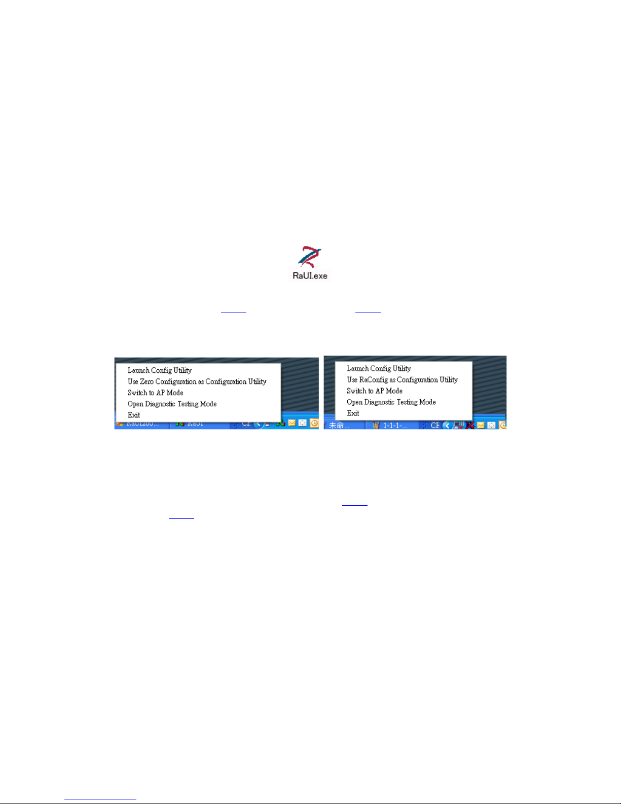
Right-clicking the icon will bring up the selection window and allow the user to make
a selection.
Figure 1-1 RaUI.exe
RaUI can co-exist with WZC. When coexisting with WZC, RaUI only provides
monitoring functions, such as surveying the link status, network status, statistic
counters, advanced feature status, WMM status and WPS status. It won't interfere
with WZC's configuration or profile functions. It is shown as Figure 1-2.
Figure 1-2 Select WZC or RaUI
If "Use RaConfig as Configuration utility" is selected, please jump to Section 2 on
running RaUI.
If "Use Zero Configuration as Configuration utility" is selected, please continue.
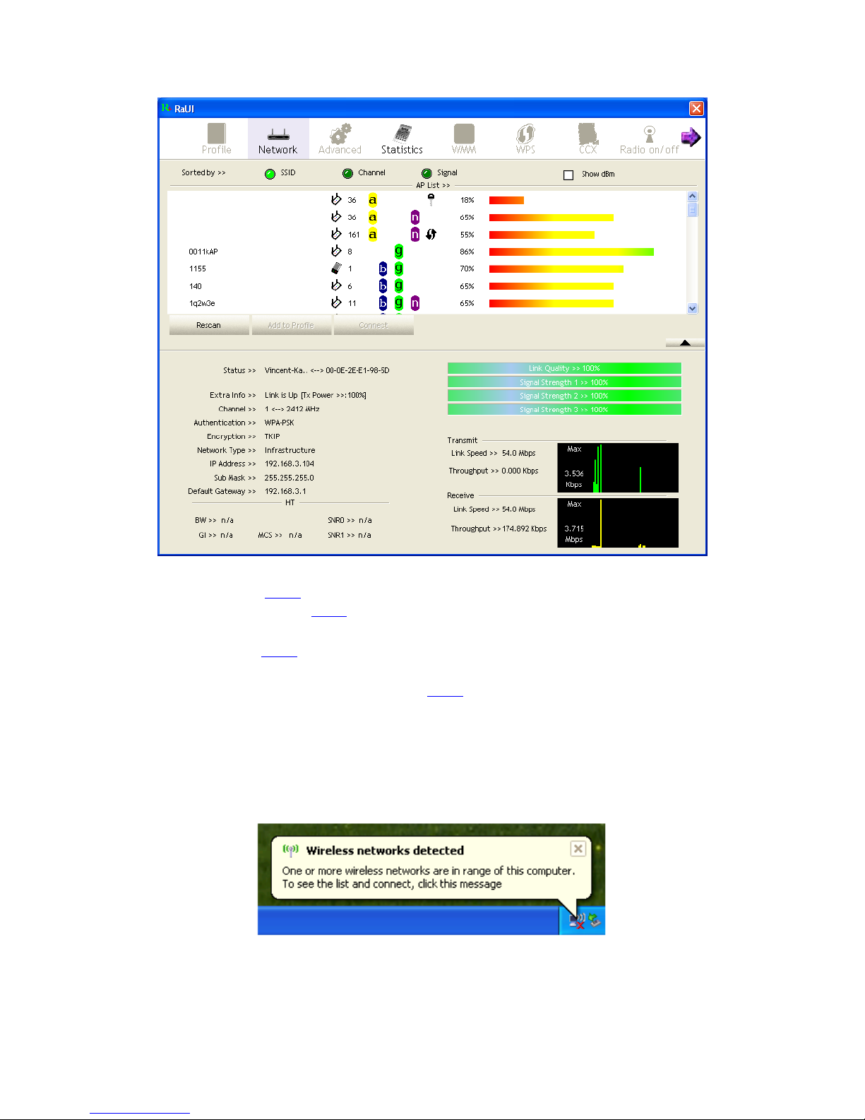
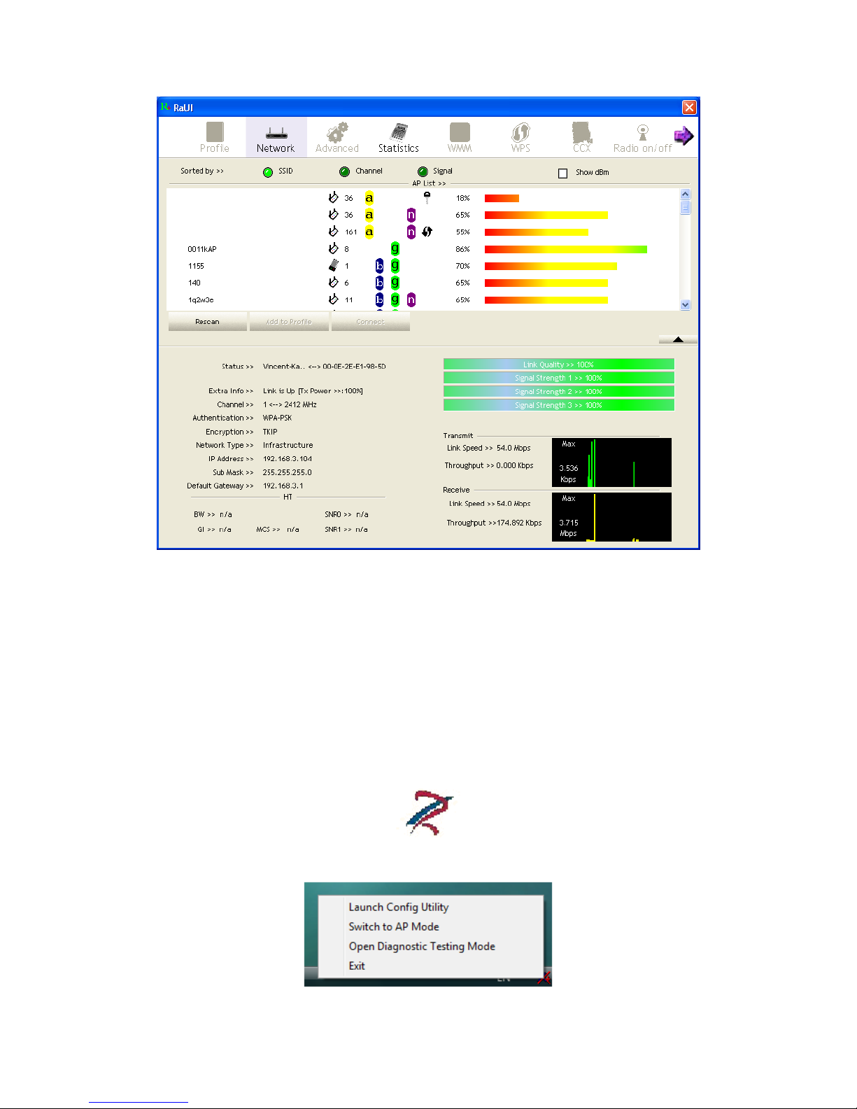
We will explain the difference between RaUI and WZC. Figure 1-3 shows the RaUI
status when WZC is activated as the main control utility.
Page 5
5/113
Figure 1-3 RaUI status with WZC active
When activating WZC, there are several difference with the RaUI status, compared to
the RaUI status without WZC running.
The profile button will be gray. Profile functionality is removed since the NIC is
controlled by WZC.
The Connect and Add Profile function will be gray. Profile functionality is
removed since the NIC is controlled by WZC.
Please read through this document for full details on the other functions provided by
RaUI.
1.1.2 Windows Zero Configuration (WZC)
If there is no connection or it is lost, the status prompt will pop up, as shown in
Figure 1-4.
Figure 1-4 status prompt for no connection
Right-click the network connection icon in taskbar.
Page 6
6/113
Figure 1-5 Select WZC main status
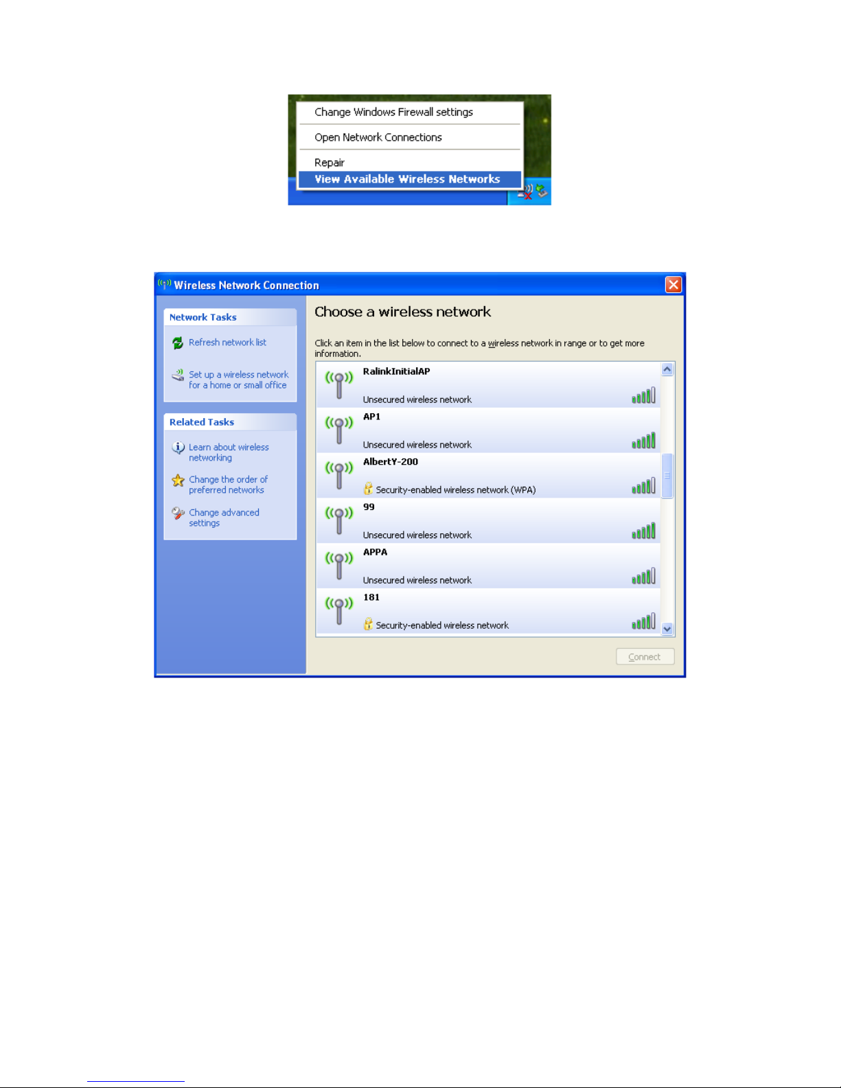
Select "View Available Wireless Networks" and the "Wireless Network
Connection" dialog box will pop up, as shown in Figure 1-6.
Figure 1-6 Wireless Network Connection
Select the intended access point and click "Connect". Then click "Connect
Anyway" as shown as Figure 1-7.
Page 7

7/113
Figure 1-7 Select intended AP : AP1, then click "Connect"
Figure 1-8 Connect AP: AP1 successfully
Page 8

8/113
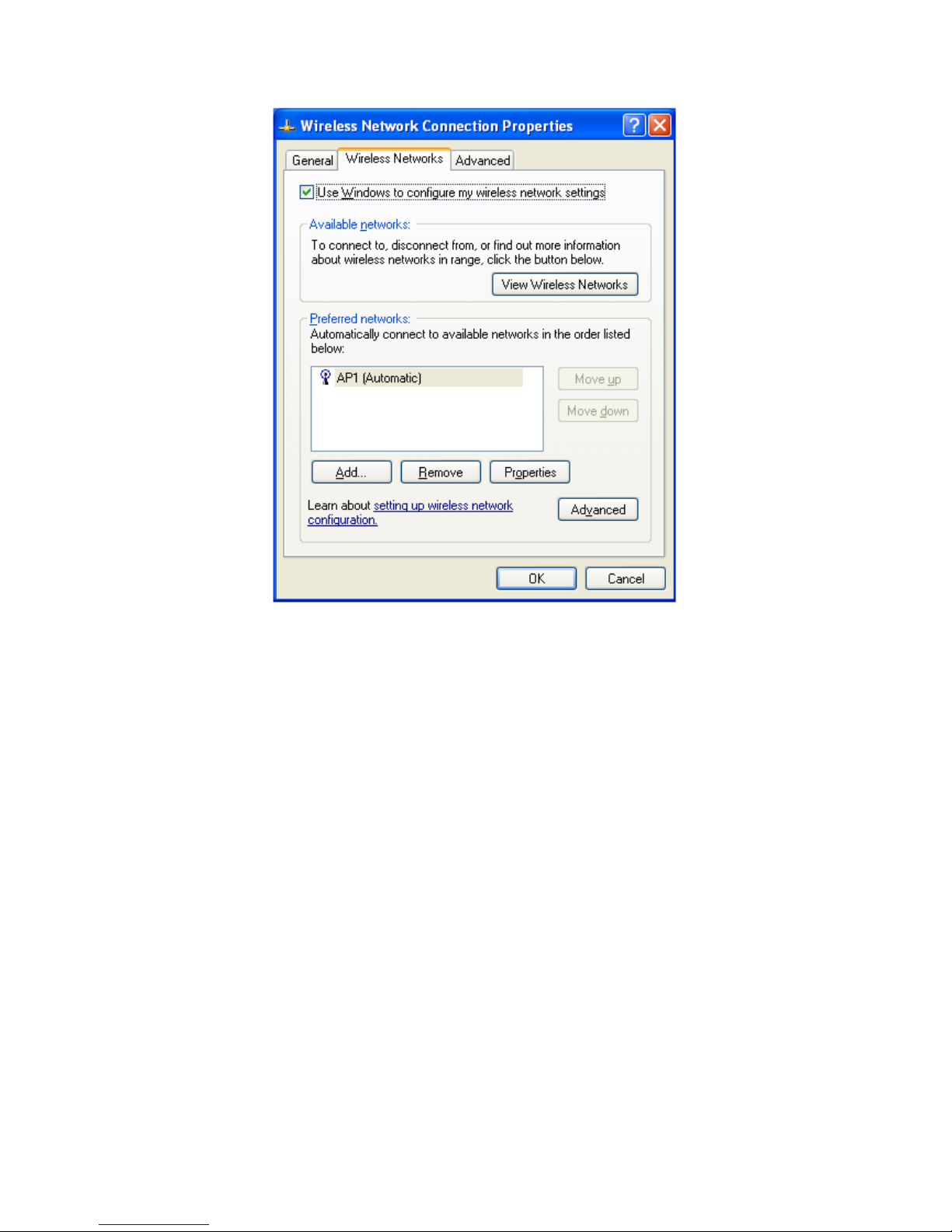
If you want to modify information about the AP, click "Change advanced settings"
as shown in Figure 1-9. Then select the "Wireless Networks" tab shown as Figure
1-10.
Figure 1-9 Click "Change advanced settings"
Page 9
9/113
Figure 1-10 Choose the "Wireless Networks" tab
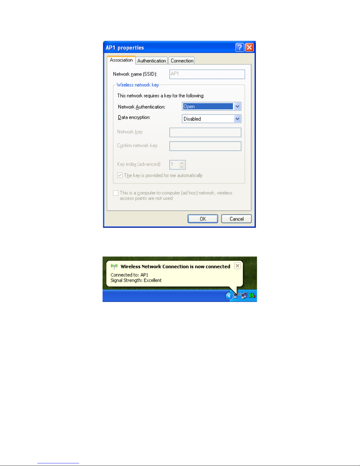
Click "Properties" as shown in Figure 1-11. Then click "OK" button.
Page 10
10/113
Figure 1-11 AP's properties
After filling in the appropriate value, click "OK." The pop-up will indicate the
status as shown in Figure 1-12.
Figure 1-12 Network connection status
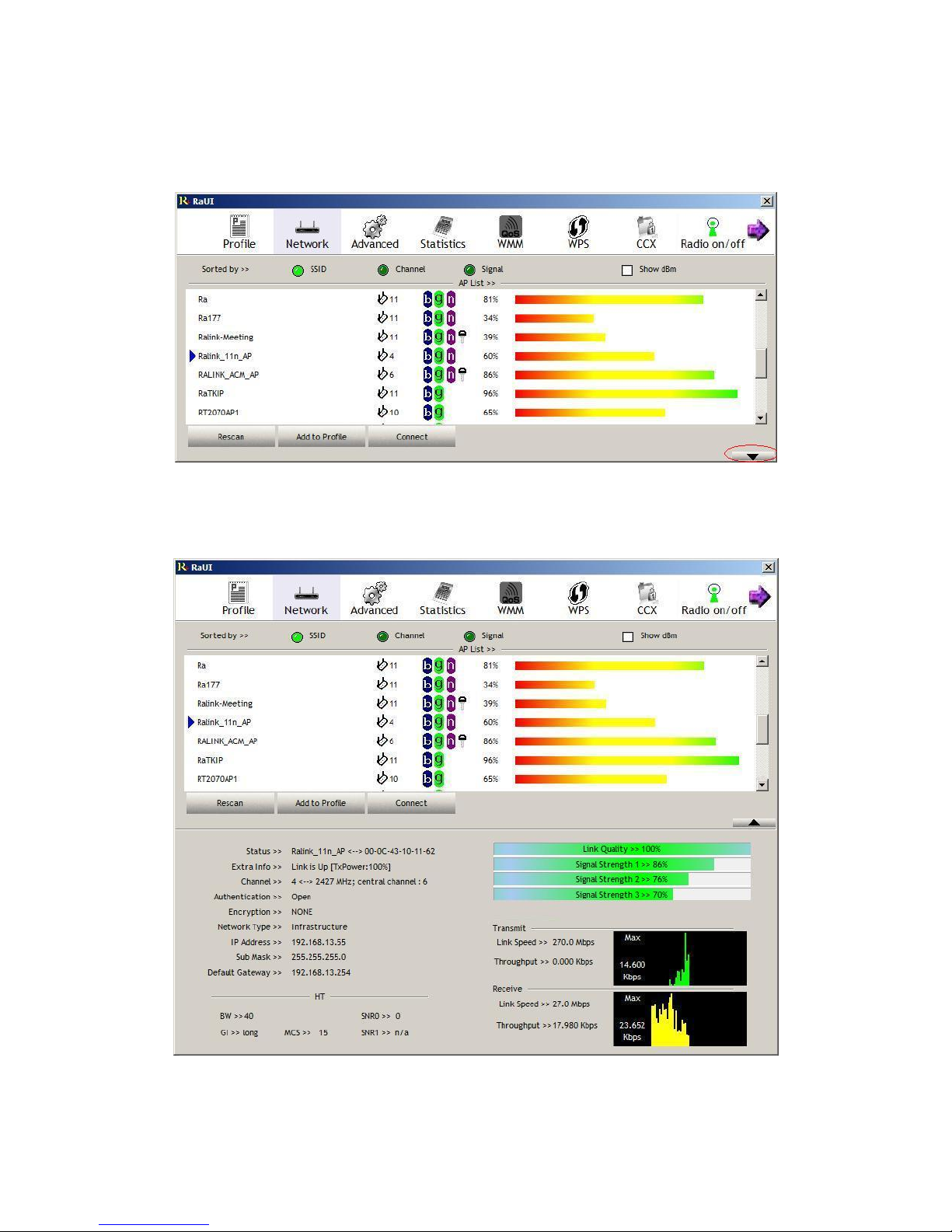
Clicking the Ralink icon will bring up the RaUI main window. Users can find the
surrounding APs in the list. The currently connected AP will be shown with a blue
icon beside it, as shown in Figure 1-13. Users may use the advanced tab to
configure more advanced features provided by Ralink's wireless NIC. For details
on configuring the advanced features, please check the Advance setting section.
Page 11
11/113
Figure 1-13 Show connection status by using WZC to initiate the connection
1.2 Windows AutoConfig Servic e for Vista
1.2.1 Ralink Wireless Utility and Windows AutoConfig Service
In Windows Vista, the Auto Config service provides basic wireless configuration
functions for the Ralink Wireless Network Interface Controller. In order to perform
these functions, the Auto Config service should first be enabled (Refer to Section
1-2-2).
Once the Ralink wireless utility is minimized, click the Ralink icon as shown in
Figure 1-1. This will bring up the option menu shown as Figure 1-2 for the user to
restore the utility window or terminate the utility.
Figure 1-1
Figure 1-2
Page 12
12/113
The Ralink wireless utility as shown in Figure 1-3, provides profile management, the
available networks listing, a statistical counter display, Wi-Fi multimedia (WMM),
protected Wi-Fi setup, Cisco compatible extensions (CCX), call admission control
(CAC), radio controls, Ralink driver/utility information, and help functions.
Figure 1-3 Ralink Utility
The Ralink wireless utility starts in compact mode as shown in Figure 1-3. Clicking
the expanding icon at the bottom-right corner can change to the full mode as shown in
Figure 1-4.
Figure 1-4 Ralink Utility in full mode
Page 13
13/113
1.2.2 Windows AutoConfig Service
The following steps outline the procedure for starting/stopping the Windows
AutoConfig service.
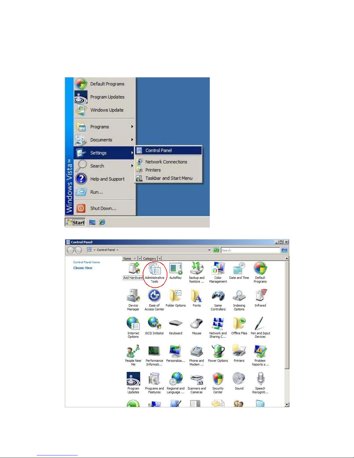
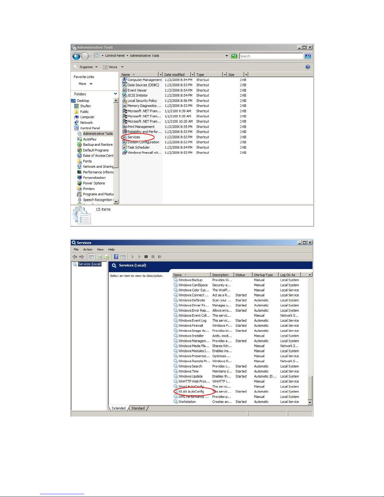
Select "Control Panel" from "Settings" in the start menu
Double-click the "Administrative Tools" icon
Double-click "Services"
Page 14
14/113
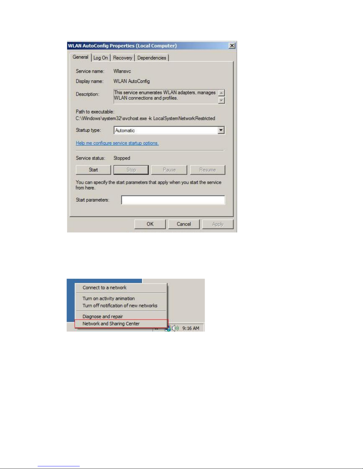
Double-click "WLAN AutoConfig"
Manage the AutoConfig properties in the dialog box
Page 15
15/113
Windows profile manager can be accessed via control panel or network
connection icon in the task bar.
1. Access via network connection icon
Right-click the network connection icon in the taskbar, then select "Network and
Sharing Center" from the pop-up menu
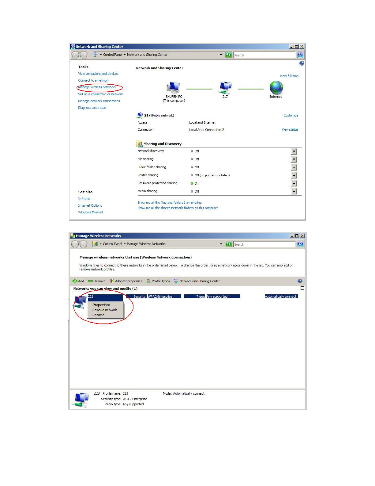
Select "Manage wireless networks" from the tasks list
Page 16
16/113
Right-click the network to bring up the profile managing menu
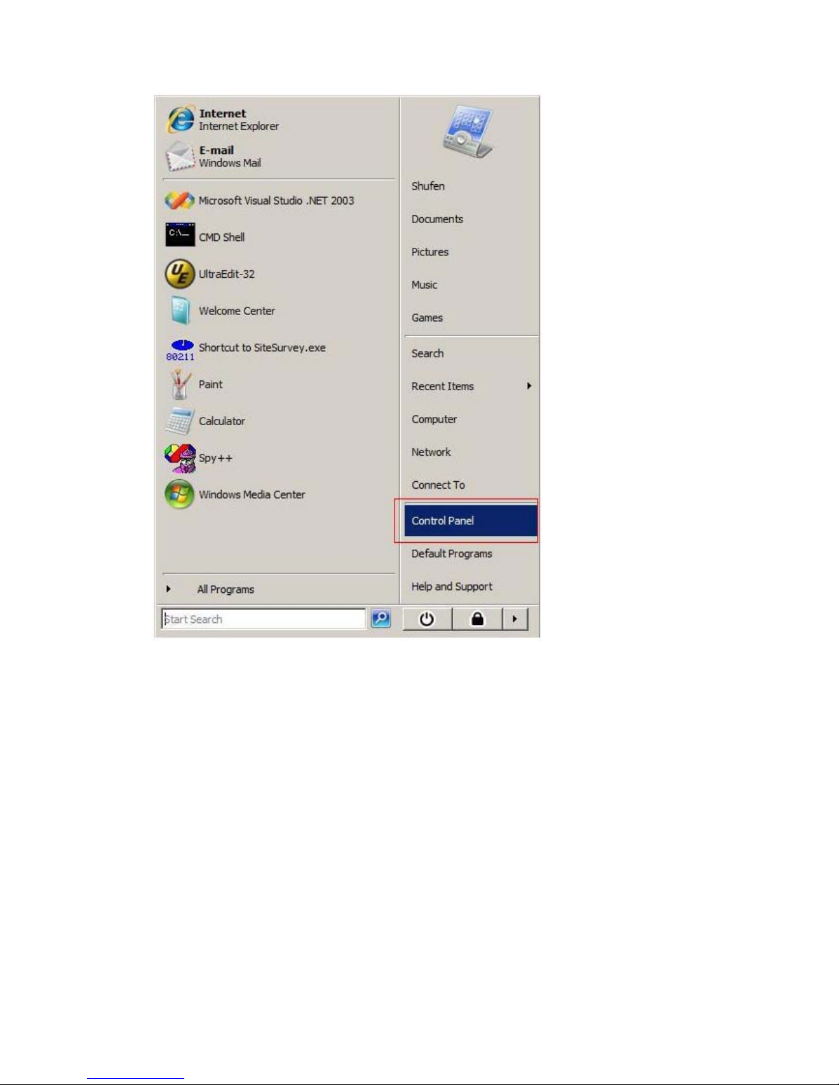
2. Access via control panel
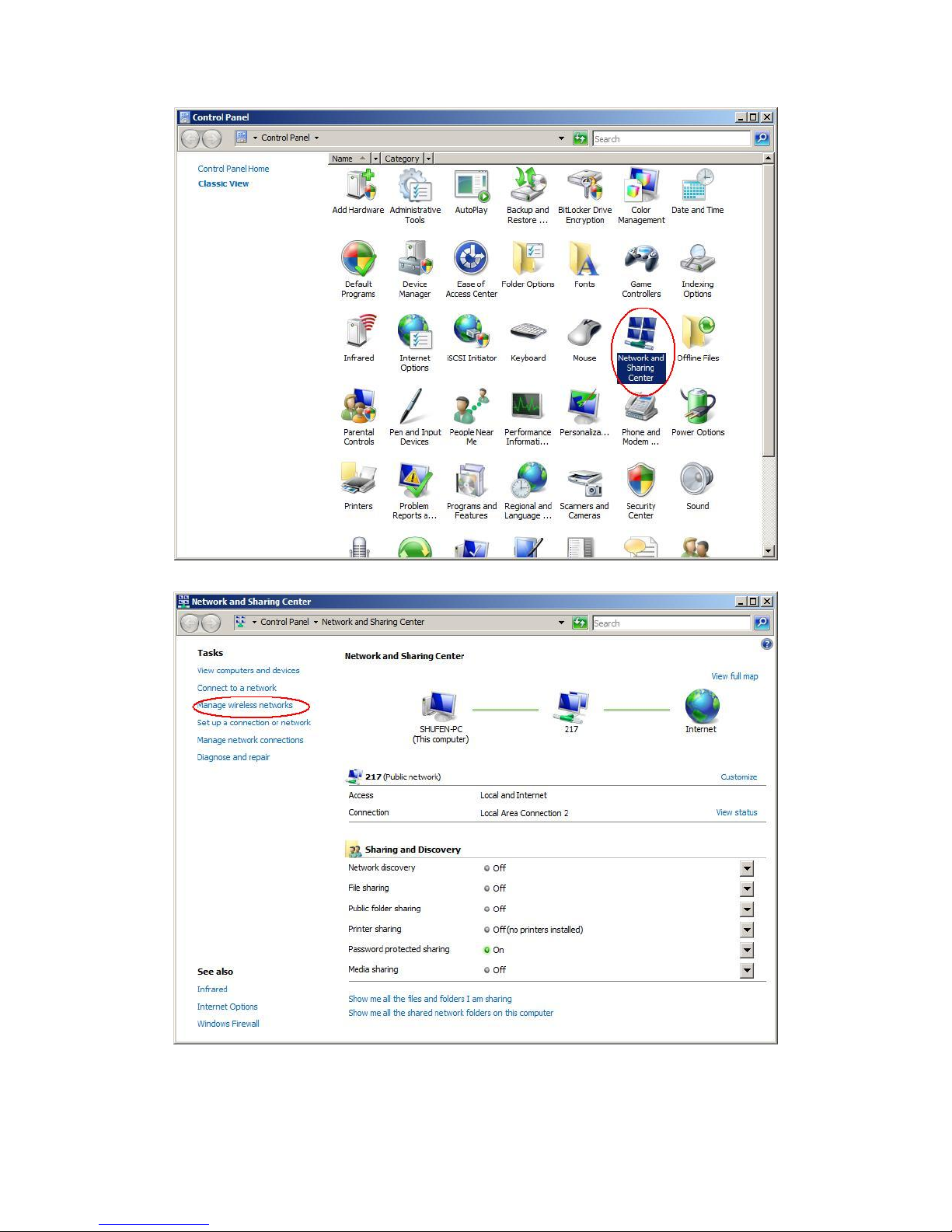
Select "Control Panel" from the start menu
Page 17
17/113
Double-click the "Network and Sharing Center" icon
Page 18
18/113
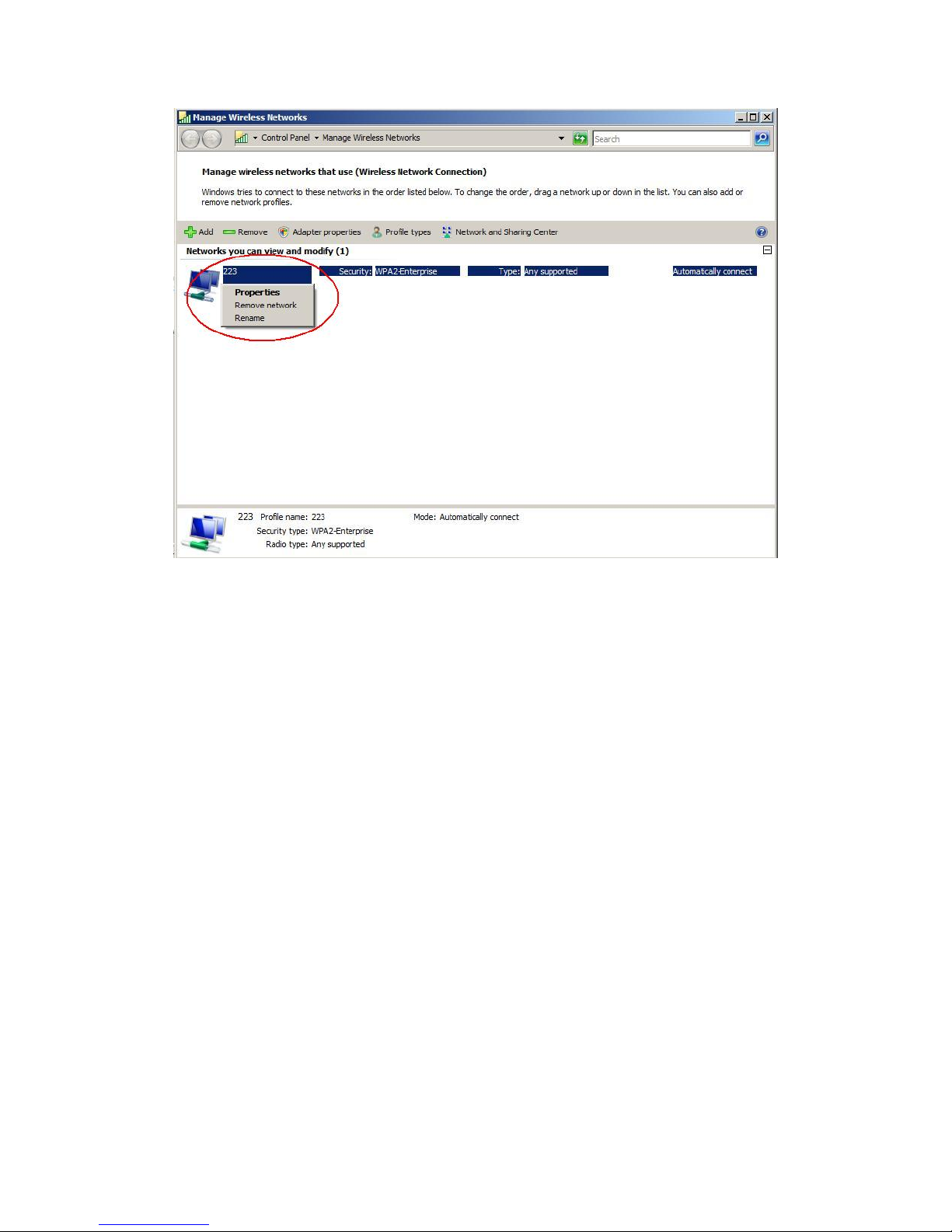
Select "Manage wireless networks" from the tasks list
Right-click the network to bring up the profile managing menu
Page 19
19/113
2. Ralink Wireless Utility (RaUI)
2.1 Start
2.1.1 Start RaUI
When starting RaUI, the system will connect to the AP with best signal strength
without setting a profile or matching a profile setting. When starting RaUI, it will
issue a scan command to a wireless NIC. After two seconds, the AP list will be
updated with the results of a BSS list scan. The AP list includes most used fields, such
as SSID, network type, channel used, wireless mode, security status and the signal
percentage. The arrow icon indicates the connected BSS or IBSS network. The dialog
box is shown in Figure 2-1.
Page 20
20/113
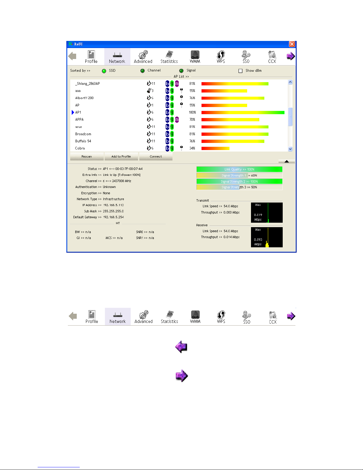
Figure 2-1-1 RaUI section introduction
There are three sections to the RaUI dialog box. These sections are briefly described
as follow.
Button Section: Include buttons for selecting the Profile page, Network page,
Advanced page, Statistics page, WMM page, WPS page, the About button, Radio
On/Off button and Help.
Figure 2-1-2 Button section
Figure 2-1-3 Move to the left
Figure 2-1-4 Move to the right
Function Section: Appears to present information and options related to the button.
Page 21
21/113
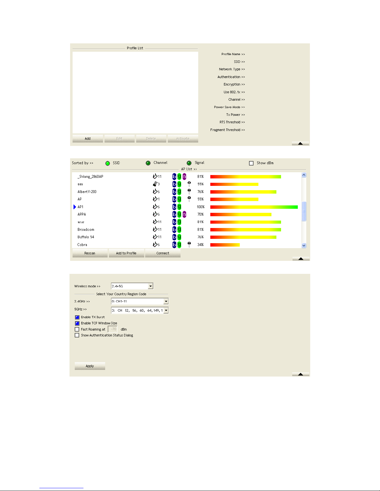
Figure 2-1-5 Profile page
Figure 2-1-6 Network page
Figure 2-1-7 Advance page
Page 22
22/113
Figure 2-1-8 Statistics page
Figure 2-1-9 WMM page
Figure 2-1-10 WPS page
Page 23
23/113
Figure 2-1-11 About page
Status Section: This section includes information about the link status, authentication
status, AP's information and configuration, and retrying the connection when
authentication is failed.
Figure 2-1-12 Link Status
Figure 2-1-13 Authentication Status
Page 24
24/113
Figure 2-1-14 AP's Information
Figure 2-1-15 Retry the connection
Figure 2-1-16 Configuration
When starting RaUI, a small Ralink icon appears in the notifications area of the
taskbar, as shown in Figure 2-1-15. You can double click it to maximize the dialog
box if you selected to close it earlier. You may also use the mouse's right button to
close RaUI utility.
Figure 2-1-17 Ralink icon in system tray
Page 25
25/113
Additionally, the small icon will change color to reflect current wireless network
connection status. The status is shown as follows:
: Indicates the connected and signal strength is good.
: Indicates the connected and signal strength is normal.
: Indicates that it is not yet connected.
: Indicates that a wireless NIC can not be detected.
: Indicates that the connection and signal strength is weak.
2.2 Profile
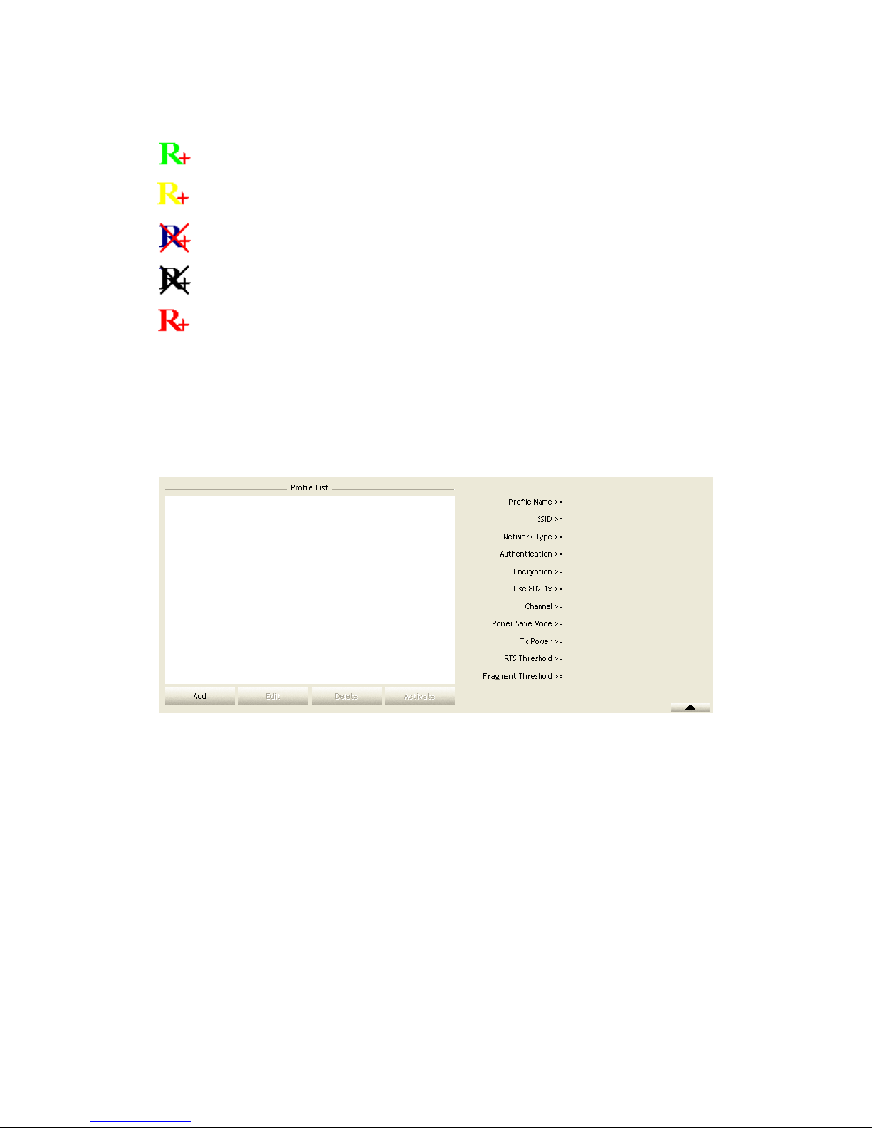
2.2.1 Profile
The Profile List keeps a record of your favorite wireless settings at home, office, and
other public hot-spots. You can save multiple profiles, and activate the correct one at
your preference. Figure 2-2-1 shows the basic profile section.
Figure 2-2-1 Profile function
Definition of each field:
Profile Name: Name of profile, preset to PROF* (* indicate 1, 2, 3...).
SSID: The access point or Ad-hoc name.
Network Type: Indicates the networks type, including infrastructure and Ad-Hoc.
Authentication: Indicates the authentication mode used.
Encryption: Indicates the encryption Type used.
Use 802.1x: Shows if the 802.1x feature is used or not.
Cannel: Channel in use for Ad-Hoc mode.
Power Save Mode: Choose from CAM (Constantly Awake Mode) or Power Saving
Mode.
Tx Power: Transmitting power, the amount of power used by a radio transceiver to
send the signal out.
RTS Threshold: Users can adjust the RTS threshold number by sliding the bar or
Page 26
26/113
keying in the value directly.
Fragment Threshold: The user can adjust the Fragment threshold number by sliding
the bar or key in the value directly.
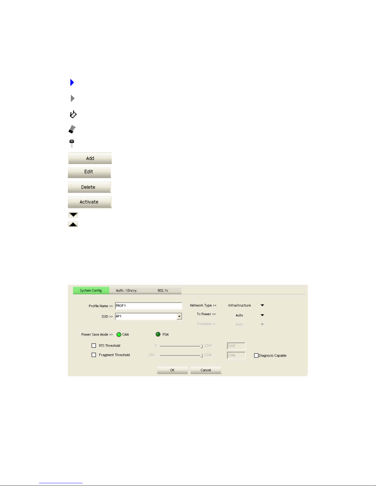
Icons and buttons:
: Indicates if a connection made from the currently activated profile.
: Indicates if the connection has failed on a currently activated profile.
: Indicates the network type is infrastructure mode.
: Indicates the network type is in Ad-hoc mode.
: Indicates if the network is security-enabled.
: Click to add a new profile.
: Click to edit an existing profile.
: Deletes an existing profile.
: Activates the selected profile.
: Shows information of the related status section.
: Hides information of the related status section.
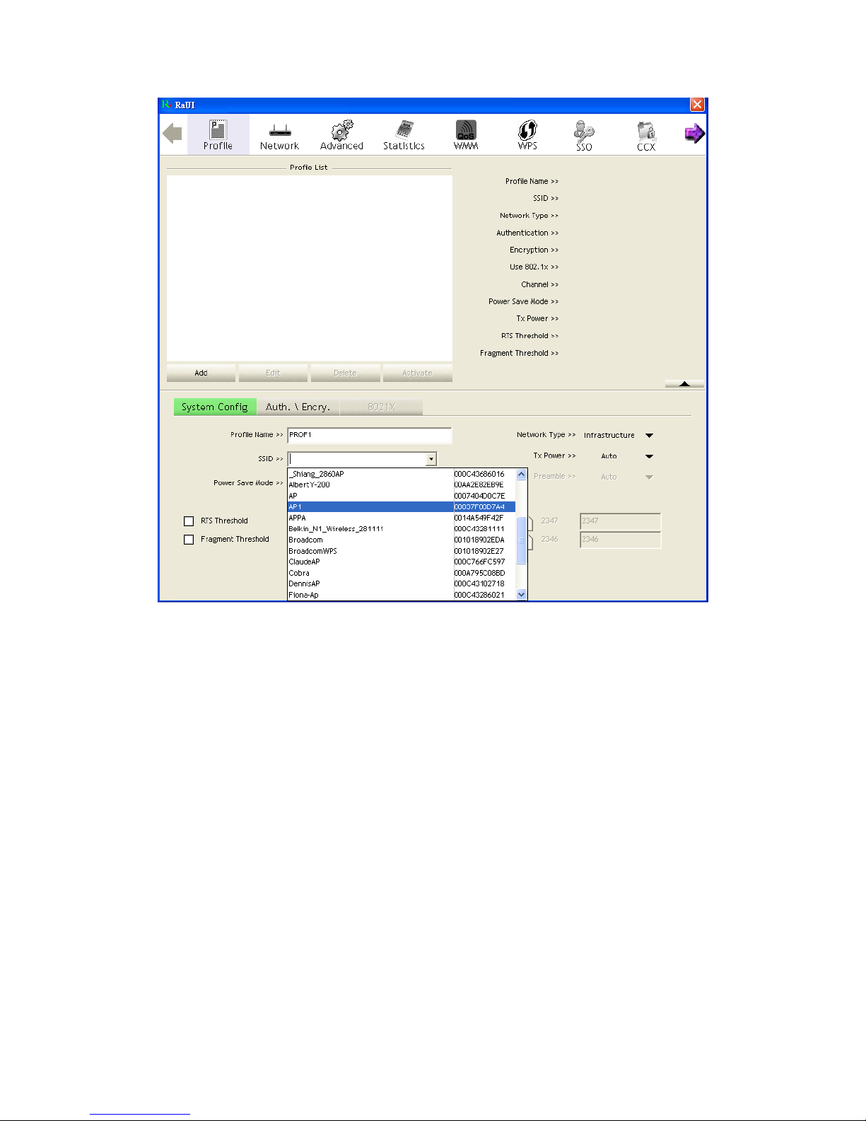
2.2.2 Add/Edit Profile
There are three methods to open the Profile Editor dialog box.
You can open it by clicking the "Add to Profile" button in the Site Survey tab.
You can open it by clicking the "Add" button in the Profile tab.
You can open it by clicking the "Edit" button on the Profile tab.
Page 27
27/113
Figure 2-2-2 Configuration
Profile Name: The user can chose any name for this profile, or use the default name
defined by system.
SSID: The user can key in the intended SSID name or select one of the available
APs from the drop-down list.
Power Save Mode: Choose CAM (Constantly Awake Mode) or Power Saving
Mode.
Network Type: There are two types, infrastructure and 802.11 Ad-hoc modes.
Under Ad-hoc mode, user can also choose the preamble type. The available
preamble type includes auto and long. In addition, the channel field will be
available for setup in Ad-hoc mode.
RTS Threshold: User can adjust the RTS threshold number by sliding the bar, or
key in the value directly. The default value is 2347.
Fragment Threshold: User can adjust the Fragment threshold number by sliding the
bar or key in the value directly. The default value is 2346.
Channel: Only available for setting under Ad-hoc mode. Users can choose the
channel frequency to start their Ad-hoc network.
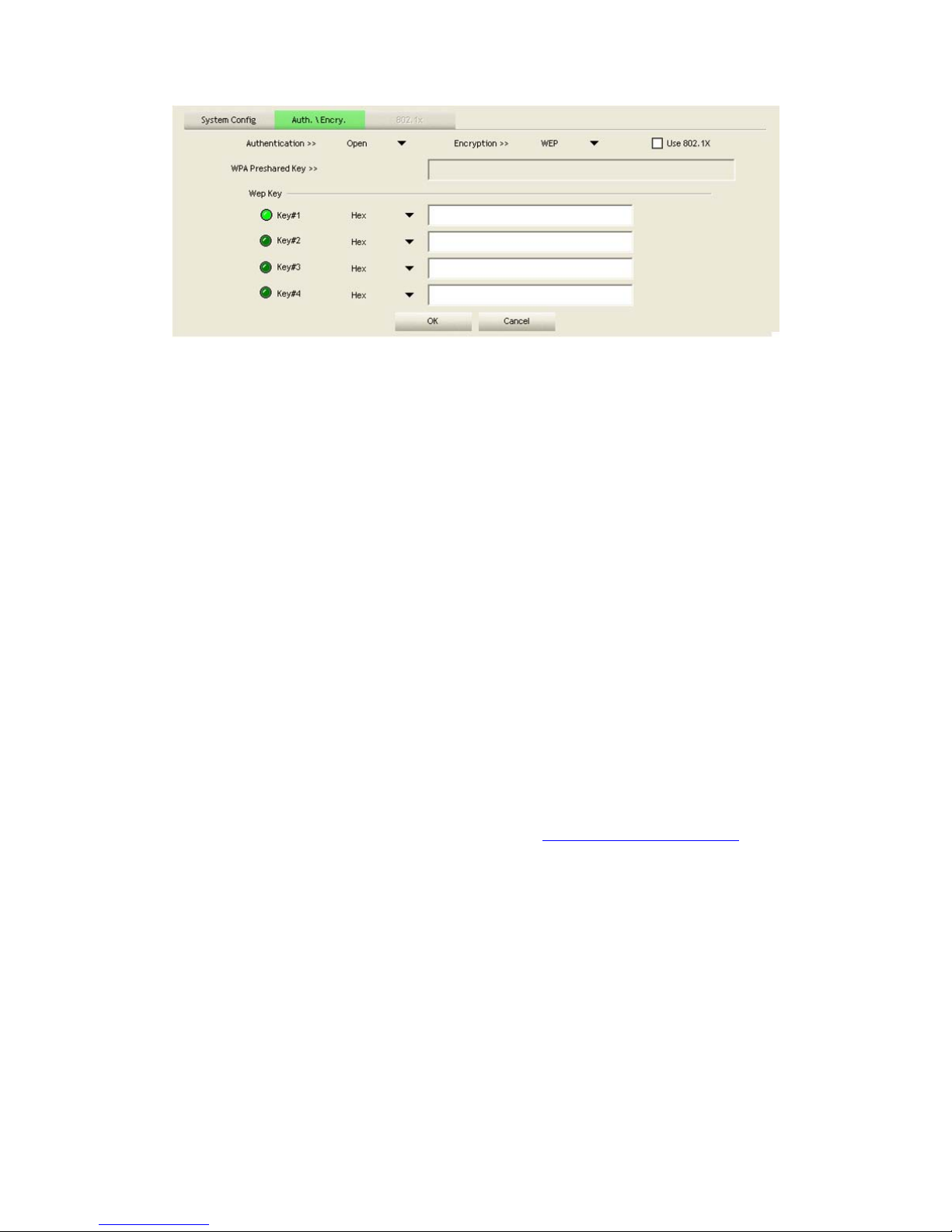
Authenticati on Type: There are 7 types of authentication modes supported by RaUI.
They are open, Shared, LEAP, WPA and WPA-PSK, WPA2 and WPA2-PSK.
Encryption Type: For open and shared authentication mode, the selection of
available encryption type are none and WEP. For WPA, WPA2, WPA-PSK and
WPA2-PSK authentication mode, both TKIP and AES encryption is available.
802.1x Setting: This is introduced in the topic of "Section 3-2 : 802.1x Setting".
Pre-shared Key: This is the key shared between the AP and STA. For WPA-PSK
and WPA2-PSK authentication mode, this field must be filled with a key between 8
and 32 characters in length.
WEP Key: Only valid when using WEP encryption algorithms. The key must be
identical to the AP's key. There are several formats to enter the keys.
1. Hexadecimal - 40bits: 10 Hex characters.
2. Hexadecimal - 128bits: 26 Hex characters.
3. ASCII - 40bits: 5 ASCII characters.
4. ASCII - 128bits: 13 ASCII characters.
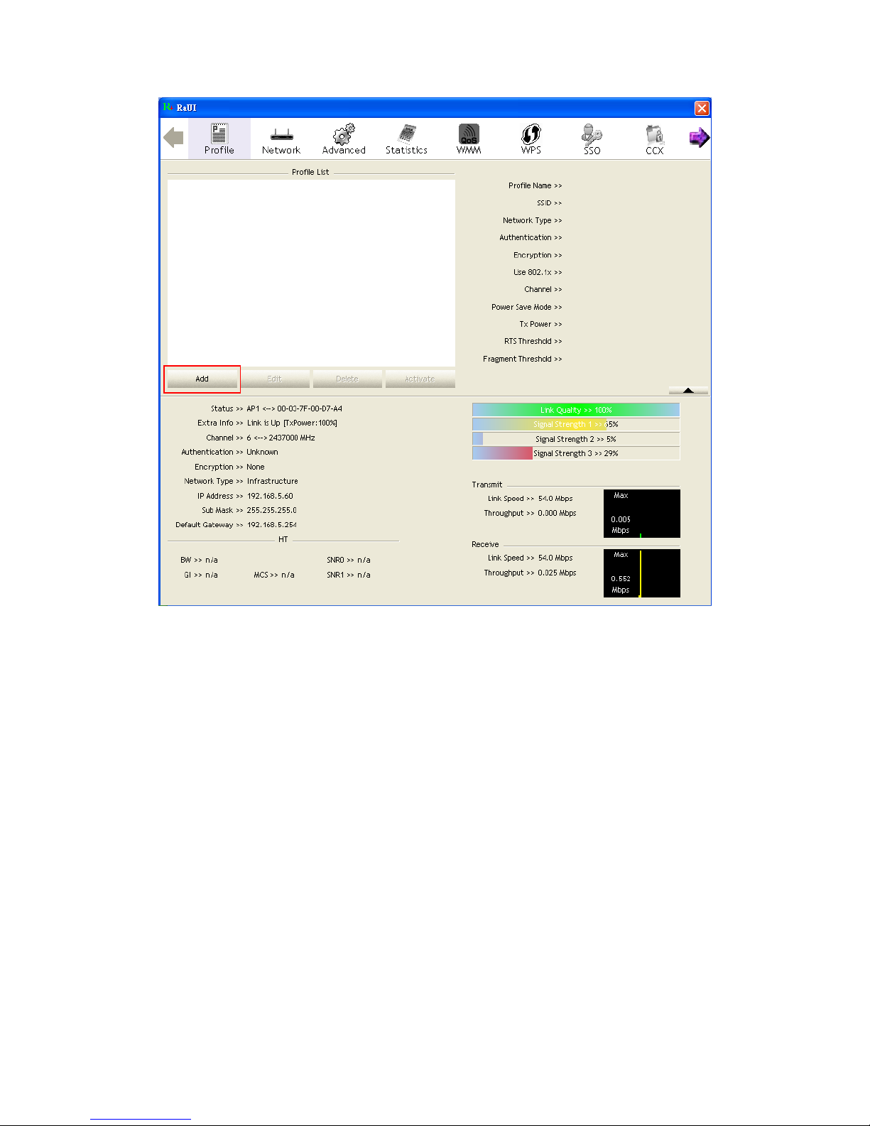
2.2.3 Example to Add Profile in Profile
Click "Add" below the Profile List.
Page 28
28/113
The "Add Profile" will appear.
Page 29
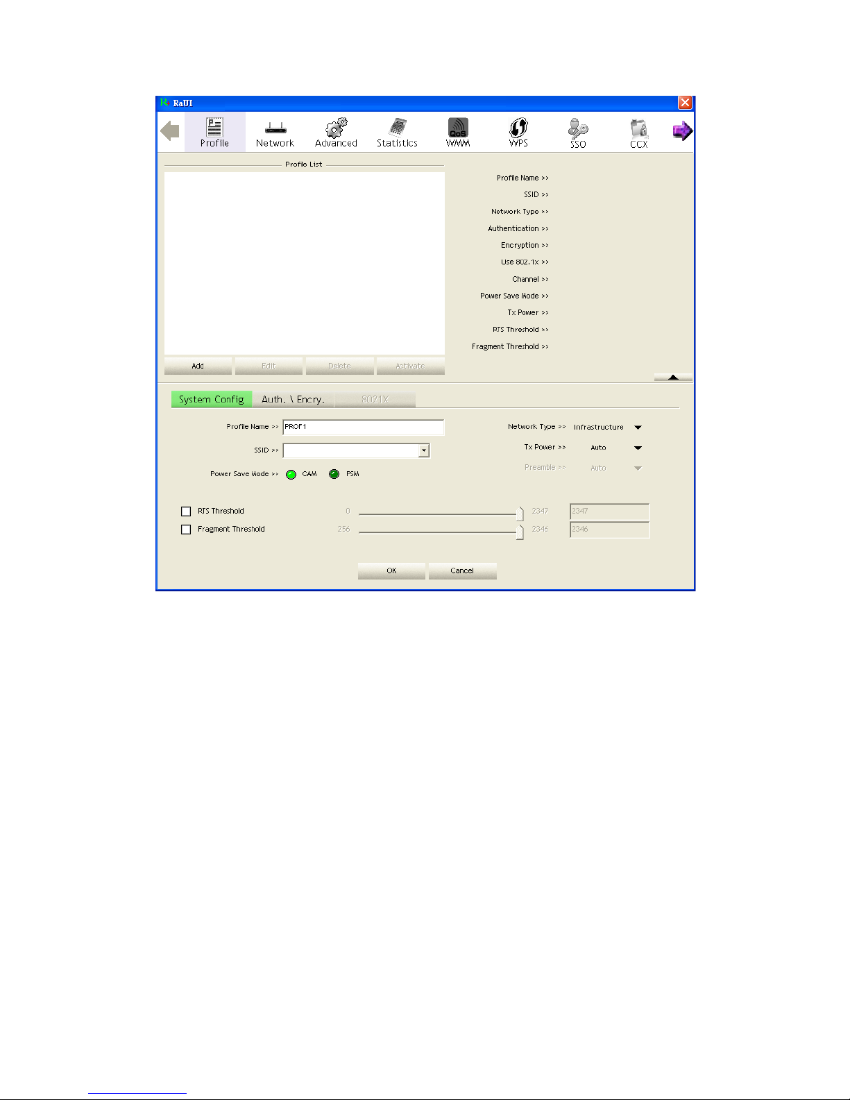
29/113
Specify a Profile Name. Select an AP from the SSID drop-down list. The AP List
from the last Network.
Page 30
30/113
Now the profile which the user set appears in the profile list. Click "Activate".
Page 31

31/113
2.3 Network
2.3.1 Network
The system will display the information of local APs from the last scan result as part
of the Network section. The Listed information includes the SSID, BSSID, Signal,
Channel, Encryption algorithm, Authentication and Network type as shown in Figure
2-3-1-1.
Figure 2-3-1-1 Network function
Page 32

32/113
Definition of each field:
SSID: Name of BSS or IBSS network.
Network Type: Network type in use, Infrastructure for BSS, Ad-Hoc for IBSS
network
Channel: Channel in use.
Wireless Mode: AP support wireless mode. It may support 802.11a, 802.11b,
802.11g or 802.11n wireless mode.
Security-Enable: Indicates if the AP provides a security-enabled wireless network.
Signal: Receive signal strength of the specified network.
Icons and buttons:
: Indicates that the connection is successful.
: Indicates the network type is in infrastructure mode.
: Indicates the network type is in Ad-hoc mode.
: Indicates that the wireless network is security-enabled.
: Indicates 802.11a wireless mode.
: Indicates 802.11b wireless mode.
: Indicates 802.11g wireless mode.
: Indicates 802.11n wireless mode.
Indicate that the AP list is sorted by SSID, Channel or Signal.
: Button to connect to the selected network.
: Issues a rescan command to the wireless NIC to update information
on the surrounding wireless network.
: Adds the selected AP to the Profile setting. It will bring up a profile
page and save the user's setting to a new profile.
: Shows the Status Section.
: Hides the Status Section.
Connected network:
When RaUI first runs, it will select the best AP to connect to automatically.
If the user wants to use another AP, they can click "Connect" for the intended AP to
make a connection.
If the intended network uses encryption other than "Not Use," RaUI will bring up the
security page and let the user input the appropriate information to make the
connection. Please refer to the example on how to fill in the security information.
When you double click an AP, you can see detailed information about that AP.
The detailed AP information is divided into three parts. They are General, WPS, CCX
information and 802.11n (The 802.11n button only exists for APs supporting N mode.)
Page 33

33/113
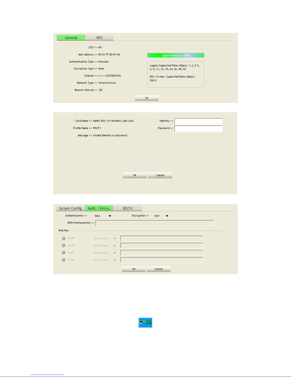
The introduction is as follows:
General information contains the AP's SSID, MAC address, authentication type,
encryption type, channel, network type, beacon interval, signal strength and supported
rates. It is shown in Figure 2-3-1-2.
Figure 2-3-1-2 General information about the Access Point
WPS information contains the authentication type, encryption type, config. methods,
device password ID, selected registrar, state, version, AP setup lock status, UUID-E
and RF bands, as shown in Figure 2-3-1-3. The information is further explained as
follows:
Authentication Type: There are three types of authentication modes supported by
RaConfig. They are open, Shared, WPA-PSK and WPA system.
Encryption Type: For open and shared authentication mode, the choices of the
encryption type are none and WEP. For WPA, WPA2, WPA-PSK and WPA2-PSK
authentication mode, the encryption type supports both TKIP and AES.
Config Methods: Correspond to the methods the AP supports as an Enrollee for
adding external Registrars, (a bitwise OR of values.)
Value Hardware Interface
0x0001 USBA (Flash Drive)
0x0002 Ethernet
Page 34

34/113
0x0004 Label
0x0008 Display
0x0010 External NFC Token
0x0020 Integrated NFC Token
0x0040 NFC Interface
0x0080 Push Button
0x0100 Keypad
Device Password ID: Indicates the method or identifies the specific password that the
selected Registrar intends to use. The AP in PBC mode must indicate 0x0004 within
the two-minute Walk Time.
Value Description
0x0000 Default (PIN)
0x0001 User-specified
0x0002 Rekey
0x0003 Display
0x0004 PushButton (PBC)
0x0005 Registrar-specified
0x0006-0x000F Reserved
Selected Registrar: Indicates if the user has recently activated a Registrar to add an
Enrollee. The values are "TRUE" and "FALSE".
State: The current configuration state of the AP. The values are "Unconfigured” and
"Configured".
Version: The specified WPS version.
AP Setup Locked: Indicates if the AP has entered a locked setup state.
UUID-E: The universally unique identifier (UUID) element generated by the Enrollee.
The value is 16 bytes.
RF Bands: Indicates all of the RF bands available to the AP. A dual-band AP must
provide it. The values are "2.4GHz” and "5GHz".
Page 35

35/113
Figure 2-3-1-3 WPS Detailed information about the AP
802.11n information contains some related 802.11n information. It is shown in Figure
2-3-1-4.
Page 36

36/113
Figure 2-3-1-4 802.11n information
2.3.2 Example on Adding Profile in Network
Select the AP from the list on the Network tab
Page 37

37/113
Click "Add to Profile"
Page 38

38/113
The System section will appear at the bottom of the Add Profile window. You can
specify your own profile name.
Page 39

39/113
Next, you will see the new profile in the profile list. Click "Activate"
Page 40

40/113
2.4 Advanced
2.4.1 Advanced
Figure 2-4 shows the Advance functions of RaUI.
Figure 2-4 Advance function
Wireless mode: Select wireless mode. 2.4G, 5G and 2.4+5G are
supported.(2.4G/5GHz options are depend on different products)
Wireless Protection: Users can choose from Auto, on, and off. (This is not
Page 41

41/113
supported by 802.11n adapters.)
Auto: STA will dynamically change as AP announcement.
On: The frames are always sent with protection.
Off: The frames are always sent without protection.
TX Rate: Manually select the transfer rate. The default setting is auto. (802.11n
wireless cards do not allow the user to select the TX Rate.)
Enable TX Burst: Ralink's proprietary frame burst mode.
Enable TCP Window Size: Optimise the TCP window size to allow for greater
throughput.
Fast Roaming at-: enables fast roaming, which is set by the transmit power.
Select Your Country Region Code: There are eight countries to choose from in the
country channel list. (11A ListBox only shows for 5G adapters.)
Show Authentication Status Dialog: When you connect to an AP with
authentication, choose whether show the "Authentication Status Dialog" or not.
The Authentication Status Dialog displays the processes during 802.1x
authentication.
Apply the above changes.
Icons and buttons:
: Show the Status Section information.
: Hide the Status Section information.
2.5 Statistics
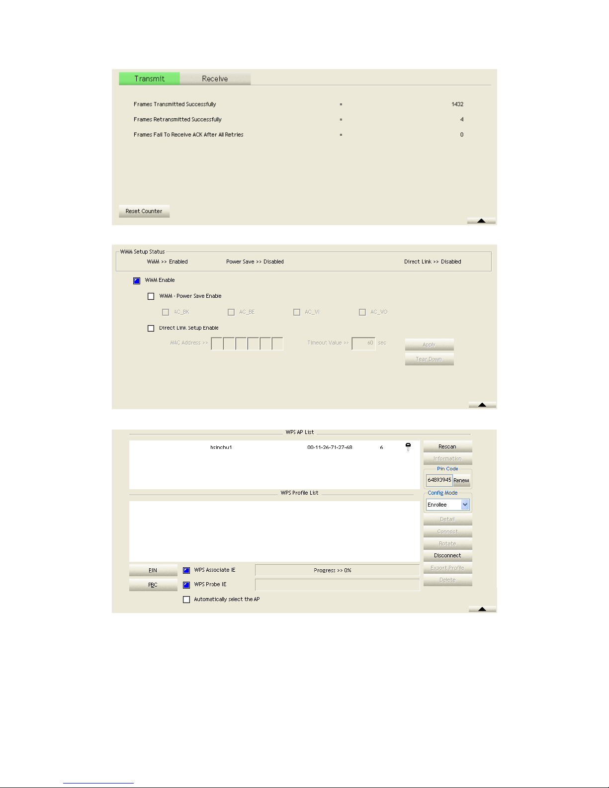
2.5.1 Statistics
The Statistics page displays detailed counter information based on 802.11 MIB
counters. This page translates that MIB counters into a format easier for the user to
understand. Figure 2-5-1 shows the detailed page layout.
Figure 2-5-1 Statistics function
Transmit Statistics:
Page 42

42/113
Frames Transmitted Successfully: Frames successfully sent.
Frames Fail To Receive ACK After All Retries: Frames failed transmit after hitting
retry limit.
RTS Frames Successfully Receive CTS: Successfully receive CTS after sending
RTS frame.
RTS Frames Fail To Receive CTS: Failed to receive CTS after sending RTS.
Frames Retransmitted Successfully: Successfully retransmitted frames numbers.
Reset counters to zero.
Receive Statistics:
Frames Received Successfully: The number of frames successfully received.
Frames Received With CRC Error: The number of frames received with a CRC
error.
Frames Dropped Due to Out-of-Resource: The number of frames dropped due to a
resource issue.
Duplicate Frames Received: The number of duplicate frames received.
Reset all the counters to zero.
Icons and buttons:
: Show the Status Section information.
: Hide the Status Section information.
Page 43

43/113
2.6 WMM
2.6.1 WMM
Figure 2-6-1 shows WMM function of RaUI. It involves "WMM Enable", "WMM Power Save Enable" and DLS setup. The introduction indicates as follow:
Figure 2-6-1 WMM function
Direct Link Setup Enable: Enable DLS (Direct Link Setup). The setting method
follows Section 2-6-2.
WMM Enable: Enable Wi-Fi Multi-Media. The setting method follows Section
2-6-3.
WMM - Power save Enable: Enable WMM Power Save. The setting method
follows Section 2-6-4.
Icons and buttons:
: Show the Status Section information.
: Hide the Status Section information.
2.6.2 Example to Configure to Enable DLS (Direct Link Setup)
Click the "Direct Link Setup Enable" checkbox
Change to "Network" function. Add an AP that supports DLS features to the
Profile. The result will look like the Profile Page in the figure below.
Page 44

44/113
The DLS settings are explained as follows:
Fill in the blanks of Direct Link with MAC Address of STA. The STA must
conform to these two conditions:
1. Connect with an AP that supports DLS features.
2. Ensure that DLS is enabled.
The Timeout Value indicates the time in seconds before it disconnects
automatically. The value is an integer. The integer must be between 0~65535. A
zero value specifies that it stays connected. The default Timeout Value is 60
Page 45

45/113
seconds.
Click "Apply"
Describe "DLS Status" as follow:
After configuring the DLS successfully, the MAC address and Timeout Value are
displayed in the "DLS Status". In "DLS Status" on the opposite side, the users’
local MAC address and Timeout Value are displayed.
Display the values of "DLS Status" to "Direct Link Setup" as follow :
1. In "DLS Status" select a direct link STA what you want to show it's values in
"Direct Link Setup".
Page 46

46/113
2. Double click. And the result will look like the below figure.
Disconnect Direct Link Setup as follow :
1. Select a direct link STA.
2. Click "Tear Down" button. The result will look like the below figure
2.6.3 Example to Configure to Enable Wi-Fi Multi-Media
If you want to use "WMM-Power Save" or "Direct Link" you must enable WMM.
The setting method of enabling WMM indicates as follows:
Click "WMM Enable".
Page 47

47/113
Change to "Network" function. And add a AP that supports WMM features to a
Profile. The result will look like the below figure in Profile page.
2.6.4 Example to Configure to Enable WMM – Power Save
Click "WMM-Power save Enable".
Page 48

48/113
Please select which ACs you want to enable. The setting of enabling WMM-Power
Save is successfully.
2.7 WPS
2.7.1 WPS
Figure 2-7-1 illustrates the RaUI WPS functions.
Page 49

49/113
Figure 2-7-1 WPS function
WPS Configuration: The primary goal of Wi-Fi Protected Setup (Wi-Fi Simple
Configuration) is to simplify the security setup and management of Wi-Fi networks.
Ralink STA supports the configuration and setup using a PIN configuration method
or a PBC configuration method through an internal or external Registrar.
WPS AP List: Displays the information of the surrounding APs with WPS IE from
the last scan result. The detailed information includes the SSID, BSSID, Channel,
ID (Device Password ID), Security-Enabled.
Rescan: Issues a rescan command to the wireless NIC to update information on the
surrounding wireless network.
Information: Displays the information about WPS IE on the selected network. The
detailed list includes the Authentication Type, Encryption Type, Config Methods,
Device Password ID, Selected Registrar, State, Version, AP Setup Locked,
UUID-E and RF Bands. Further details are available here: WPS Information on
AP.
PIN Code: The user is required to enter an 8-digit PIN Code into Registrar. When
an STA is the Enrollee, you can click "Renew" to re-generate a new PIN Code.
Config Mode: The station serving as an Enrollee or an external Registrar.
Table of Credentials: Displays all credentials obtained by the Registrar. The
detailed list includes information about the SSID, MAC Address, Authentication
and Encryption Type. If STA is the Enrollee, the credentials are cre ated
Page 50

50/113
immediately with each WPS success. If STA is the Registrar, RaUI creates a new
credential with WPA2-PSK/AES/64Hex-Key and doesn't change this until
switching to STA Registrar.
Control items for credentials.
1. Detail: Command to obtain Information about Security and the Key in the
credential.
2. Connect: Command to connect to the selected network inside credentials. The
active selected credential is as like as the active selected Profile.
3. Rotate: Command to rotate to connect to the next network inside credentials.
4. Disconnect: Stops the WPS action and disconnects the active link. It then selects
the most recent profile on the Profile Page of RaUI. If there are no profiles, the driver
will select any non-security AP.
5. Export Profile: Exports all credentials to a Profile.
6. Delete: Deletes an existing credential. And then selects the next credential. If there
is not another credential, the driver will select any non-security AP.
PIN: Start to add to Registrar using PIN configuration method. If STA Registrar,
remember that enter PIN Code read from your Enrollee before starting PIN.
PBC: Start to add to AP using PBC configuration method.
After the user clicks PIN or PBC, please do not rescan within two-minutes of the
connection. If you want to abort this setup within the interval, restart PIN/PBC or
click "Disconnect" to stop WPS action.
WPS associate IE: Sends the association request with WPS IE during the WPS
setup. It is optional for STA.
WPS probe IE: Sends the probe request with WPS IE during WPS setup. It is
optional for STA.
Progress Bar: Displays the rate of progress from Start to Connected.
Status Bar: Displays the current WPS Status.
Automatically select the AP: Starts to add to AP by using to select the AP
automatically in PIN method.
**There are examples in section 2-7-3(PIN Enrollee Setup), section 2-7-4(PBC
Enrollee Setup) and section 2-7-5(Registrar Configures and AP)**
Icons and buttons:
: Show the Status Section information.
: Hide the Status Section information.
2.7.2 WPS Information on AP
The WPS information (shown below) includes the authentication type, encryption
type, config methods, device password ID, selected registrar, state, version, AP setup
locked, UUID-E and RF bands.
Page 51

51/113
Authentication Type: There are three authentication modes supported by RaConfig.
They are open, Shared, WPA-PSK and WPA system.
Encryption Type: For open and shared authentication mode, the selection of
encryption type are none and WEP. For WPA, WPA2, WPA-PSK and WPA2-PSK
authentication mode, the encryption type supports both TKIP and AES.
Config Methods: Correspond to the methods the AP supports as an Enrollee for
adding external Registrars. (a bitwise OR of values)
Value Hardware Interface
0x0001 USBA (Flash Drive)
0x0002 Ethernet
0x0004 Label
0x0008 Display
0x0010 External NFC Token
0x0020 Integrated NFC Token
0x0040 NFC Interface
0x0080 Push Button
Page 52

52/113
0x0100 Keypad
Device Password ID: Indicates the method or identifies the specific password that
the selected Registrar intends to use. APs in PBC mode must indicate 0x0004
within two-minute Walk Time.
Value Description
0x0000 Default (PIN)
0x0001 User-specified
0x0002 Rekey
0x0003 Display
0x0004 PushButton (PBC)
0x0005 Registrar-specified
0x0006-0x000F Reserved
Selected Registrar: Indicates if the user has recently activated a Registrar to add an
Enrollee. The values are "TRUE" and "FALSE".
State: The current configuration state on AP. The values are "Unconfigured” and
"Configured".
Version: WPS specified version.
AP Setup Locked: Indicates if the AP has entered a setup locked state.
UUID-E: The universally unique identifier (UUID) element generated by the
Enrollee. This is a 16 byte value.
RF Bands: Indicates all the RF bands available on the AP. A dual-band AP must
provide it. The values are "2.4GHz” and "5GHz".
2.7.3 Example to Add to Registrar Using PIN Method
The user obtains a device password (PIN Code) from the STA and enters the
password into the Registrar. Both the Enrollee and the Registrar use PIN Config
method for the configuration setup. The following image outlines the process.
Page 53

53/113
Select "Enrollee" from the Config Mode drop-down list.
Click "Rescan" to update available WPS APs.
Page 54

54/113
Select an AP (SSID/BSSID) that STA will join to.
Click "PIN" to enter the PIN
Enter the PIN Code of the STA into the Registrar when prompted by the Registrar.
Allow of an exchange between Step 4 and Step 5.
If you use Microsoft Window Connection Now as an External Registrar, you must
Page 55

55/113
start PIN connection at STA first. After that, search out your WPS Device name and
MAC address at Microsoft Registrar. Add a new device and enter PIN Code of STA at
Microsoft Registrar when prompted.
The result should appear as the image below.
Configure one or more credentials
Then connect successfully. The results appear as the following image.
Page 56

56/113
Click "Detail"
You will look like the below figure.
If Credential#1 is reliable and present, the system will connect with Credential#1. If
not, the system will automatically rotate to the next existing credential.
The user can also click "Rotate" to rotate to the next credential usable credential.
Describe "WPS Status Bar" - "PIN - xxx" as follow:
Acceptable PIN Configurations:
Start PIN connection - SSID ~> Begin associating to WPS AP ~> Associated to WPS
Page 57

57/113
AP ~> Sending EAPOL-Start ~> Sending EAP-Rsp (ID) ~> Receive EAP-Req (Start)
~> Sending M1 ~> Received M2 ~> (Received M2D ~> Sending EAP-Rsp (ACK))
~> Sending M3 ~> Received M4 ~> Sending M5 ~> Received M6 ~> Sending M7 ~>
Received M8 ~> Sending EAP-Rsp(Done) ~> Configured ~> WPS status is
disconnected ~> WPS status is connected successfully-SSID
WPS configuration doesn't complete after a two-minute connection:
WPS EAP process failed.
When errors occur within two minutes of connecting, the WPS status bar might
report "WPS EAP process failed".
Error messages might be:
1. Receive EAP with wrong NONCE.
2. Receive EAP without integrity.
3. Error PIN Code.
4. An inappropriate EAP-FAIL received.
2.7.4 Example to Add to Registrar Using PBC Method
The PBC method requires the user to press a PBC button on both the Enrollee and the
Registrar within a two-minute interval called the Walk Time. If there is only one
Registrar in PBC mode, the PBC mode selected is obtained from ID 0x0004, and is
found after a complete scan. The Enrollee can then immediately begin running the
Registration Protocol.
If the Enrollee discovers more than one Registrar in PBC mode, it MUST abort its
connection attempt at this scan and continue searching until the two-minute timeout.
*Before you press PBC on STA and candidate AP. Make sure all APs aren't PBC
mode or APs using PBC mode have left their Walk Time.
Select "Enrollee" from the Config Mode drop-down list.
Page 58

58/113
Click PBC to start the PBC connection.
Push the PBC on AP.
*Allow time for an exchange between Step 2 and Step 3.
The progress bar as shown in the figure below indicates that scanning progress.
When one AP is found, join it.
Page 59

59/113
Check WPS Information on the available WPS APs
Configure and receive one or more credential(s).
Then connect successfully. The result will be displayed as it is in the figure below.
Page 60

60/113
Describe "WPS Status Bar" - “PBC - xxx" as follow:
A successful PBC Configuration:
Start PBC connection ~> Scanning AP ~> Begin associating to WPS AP ~>
Associated to WPS AP ~> Sending EAPOL-Start ~> Sending EAP-Rsp (ID) ~>
Receive EAP-Rsp (Start) ~> Sending M1 ~> Received M2 ~> Sending M3 ~>
Received M4 ~> Sending M5 ~> Received M6 ~> Sending M7 ~> Received M8 ~>
Sending EAP-Rsp (Done) ~> Configured ~> WPS status is disconnected ~> WPS
status is connected successfully-SSID
No PBC AP available:
Scanning AP ~> No PBC AP available ~> Scanning AP ~> No PBC AP available
~>...
Too Many PBC AP available:
Scanning AP ~> Too Many PBC AP available ~> Scanning AP ~> Too Many PBC
AP available ~>...
WPS configuration doesn't complete after two-minute connection:
WPS EAP process failed.
When Errors occur within two-minutes of establishing a connection, the WPS status
bar might report "WPS EAP process failed".
Error messages might be:
1. Receive EAP with wrong NONCE.
2. Receive EAP without integrity.
3. An inappropriate EAP-FAIL received.
Describe "Multiple PBC session overlaps" as follow:
Dual bands:
AP1 is a G-Band AP using PBC mode. (ID = 0x0004)
AP2 is a A-Band AP using PBC mode. (ID = 0x0004)
They have the same UUID-E.
STA would regard these two APs as a dual-radio AP and select one band to connect.
Different UUID-E :
AP1 is a G-Band AP using PBC mode. (ID = 0x0004)
AP2 is a G-Band AP using PBC mode. (ID = 0x0004)
Page 61

61/113
They have the different UUID-E.
STA would regard these two APs as two different APs and wait until only one PBC
AP is available.
2.7.5 Example to Configure a Network/AP Using PIN or PBC Method
Select Registrar from the Config Mode drop-down list.
Enter the details of the credential and change configurations (SSID, Authentication,
Encryption and Key) manually if needed.
Page 62

62/113
If the PIN configuration is setup, enter the PIN sent from the Enrollee.
Start PIN or PBC. The following procedures are as similar as section 2-7-3 (PIN
Enrollee Setup) or section 2-7-4(PBC Enrollee Setup),
If your AP Enrollee has been configured before the WPS process, the credential you
set in advance will be updated to the AP itself. Otherwise, after a successful
registration, the AP Enrollee will be re-configured with the new parameters, and the
STA Registrar will connect to the AP Enrollee with these new parameters.
Describe "WPS Status Bar" - "PIN - xxx" as follow:
A successful PIN Configuration:
Page 63

63/113
Start PIN connection - SSID ~> Begin associating to WPS AP ~> Associated to WPS
AP ~> Sending EAPOL-Start ~> Sending EAP-Rsp (ID) ~> Receive M1 ~> Sending
M2 ~> Receive M3 ~> Sending M4 ~> Receive M5 ~> Sending M6 ~> Receive M7
~> Sending M8 ~> Receive EAP Rsp (Done) ~> Sending EAP Rsp (ACK) ~>
Configured ~> WPS status is disconnected ~> WPS status is connected
successfully-SSID
Describe "WPS Status Bar" - “PBC - xxx" as follow:
A successful PBC Configuration:
Start PBC connection ~> Scanning AP ~> Begin associating to WPS AP ~>
Associated to WPS AP ~> Sending EAPOL-Start ~> Sending EAP-Rsp (ID) ~>
Receive M1 ~> Sending M2 ~> Receive M3 ~> Sending M4 ~> Receive M5 ~>
Sending M6 ~> Receive M7 ~> Sending M8 ~> Receive EAP Rsp (Done) ~>
Sending EAP Rsp (ACK) ~> Configured ~> WPS status is disconnected ~> WPS
status is connected successfully-SSID
2.8 SSO
2.8.1 SSO
The SSO configuration page as shown in Figure 2-8-1.
Figure 2-8-1 SSO Page
Field definitions:
Enable SSO feature: Choose which SSO methods to log on
Use ID and Password in Winlogon: Use the ID and password in Windows logon
Use ID and Password in Profile: Use the ID and password in RaUI profile settings
Use ID and Password in Dialog: Use the ID and password in pop-up authentication
dialog
Enable Persistent Connection: Use ID and Password in the previous activated Profile
and not shows any authentication dialog
Profile List (only support LEAP or EAP-FAST authentication)
Select Profile: Select a profile containing LEAP or EAP-Fast authentication
Information of selected profile: Profile information, such as profile name, SSID.
The meaning of the button:
Page 64

64/113
: Hit the Apply button to make the settings effective
2.9 CCX
2.9.1 CCX
The CCX configuration page as shown in Figure 2-9-1.
Figure 2-9-1 CCX Page
Field definitions:
Enable CCX (Cisco Compatible eXtensions): Choose whether Cisco Compatible
eXtensions are supported or not.
Enable Radio Measurement: Enable the radio measurement, the non-serving
channel measurement limit is between 0 and 1023 milliseconds.
Roaming with RF Parameters: Roaming by a set of RF parameters from AP
Voice Drastic Roaming: Diagnose roaming function by voice traffic test
CAC (Tolerance) : Enable the call admission control
Diagnostic: Select a profile which the user want to diagnose, then hit the Diagnose
button to perform the diagnostic test
Busy Sense: Force Wireless NIC to detect noise more sensitively
The meaning of the button:
: Hit the Apply button to make the settings effective
2.10 About
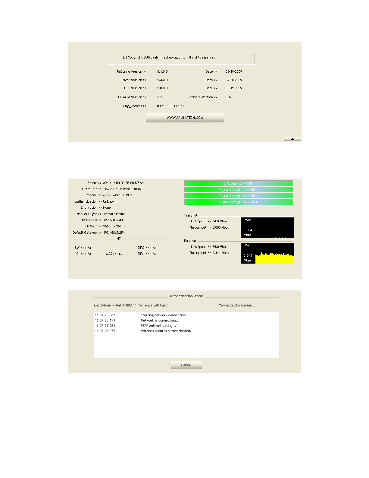
2.10.1 About
Click "About" displays the wireless card and driver version information as shown in
Figure 2-10.
Page 65

65/113
Figure 2-10 about function
Connect to Ralink's website: Ralink Technology, Corp.
Display Configuration Utility, Driver, and EEPROM version information.
Display Wireless NIC MAC address.
Icons and buttons:
: Show the information of Status Section.
: Hide the information of Status Section.
2.11 Link Status
2.11.1 Link Status
The link status page displays detailed information about the current connection as
shown in Figure 2-11.
Figure 2-11 Link Status function
Status: Current connection status. If no connection, if will show Disconnected.
Otherwise, the SSID and BSSID will show here.
Extra Info: Display link status in use.
Channel: Display current channel in use.
Authentication: Authentication mode in use.
Encryption: Encryption type in use.
Network Type: Network type in use.
Page 66

66/113
IP Address: IP ad dress about current connection.
Sub Mask: Sub mask about current connection.
Default Gateway: Default gateway about current connection.
Link Speed: Show current transmit rate and receive rate.
Throughout: Display transmits and receive throughput in unit of Mbps.
Link Quality: Display connection quality based on signal strength and TX/RX
packet error rate.
Signal Strength 1: Receive signal strength 1, user can choose to display as
percentage or dBm format.
Signal Strength 2: Receive signal strength 2, user can choose to display as
percentage or dBm format.
Signal Strength 3: Receive signal strength 3, user can choose to display as
percentage or dBm format.
HT: Display current HT status in use, containing BW, GI, MCS, SNR0, and SNR1
value. (Show the information only for 802.11n wireless card.)
2.12 SoftA P(On ly W indows 7 support)
2.12.1 SoftAP(Only W indow7 support )
Windows 7 allows wireless device to be in both station (STA) and AP mode.
According to following steps, you can open or close AP function.
Click "Switch to STA+AP mode" item in RaUI system tray menu as shown in Figure
2-12-1.
Figure 2-12-1 Switch to STA+AP Mode
Page 67

67/113
Set SoftAP SSID and key as shown in Figure 2-12-2.
Figure 2-12-2 Set SSID and key
Select WAN adapter as shown in Figure 2-12-3.
Page 68

68/113
Figure 2-12-3 Select WAN adapter
Select SoftAP page to set SoftAP parameter as shown in Figure 2-12-4.
Figure 2-12-4 Select SoftAP page
Set SoftAP parameter in SoftAP page as shown in Figure 2-12-5.
Page 69

69/113
Figure 2-12-5 Set SoftAP parameter
Click "Switch to STA mode" to close SoftAP function as shown in Figure 2-12-6.
Page 70

70/113
Figure 2-12-6 Switch to STA mode
SoftAP function is closed as shown in Figure 2-12-7.
Figure 2-12-7 STA mode
Page 71

71/113
3. Security
3.1 Auth.\ Encry. Setting – WEP/TKIP/AES
Figure 3-1 Auth. \Encry. Settings
Authentication Type : There are 7 authentication modes supported by RaUI. They
are Open, Shared, WPA and WPA-PSK, WPA2 and WPA2-PSK.
Encryption Type: For open and shared authentication mode, the available
encryption types are none and WEP. For WPA, WPA2, WPA-PSK and WPA2-PSK
authentication mode, the encryption type supports both TKIP and AES.
8021X: This is introduced in the topic of Section 3-2.
Pre-shared Key: This is the shared key between the AP and STA. If operating in
WPA-PSK and WPA2-PSK authentication mode, this field must be filled with a
key between 8 and 32 characters in length.
WEP Key: Only valid when using WEP encryption algorithm. The key must match
the AP's key. There are several formats to enter the keys.
1. Hexadecimal - 40bits: 10 Hex characters.
2. Hexadecimal - 128bits: 32Hex characters.
3. ASCII - 40bits: 5 ASCII characters.
4. ASCII - 128bits: 13 ASCII characters.
3.2 802.1x Setting
802.1x is used for authentication of the "WPA" and "WPA2" certificate by the server.
Authentication type:
Page 72

72/113
PEAP: Protect Extensible Authentication Protocol. PEAP transport securely
authenticates data by using tunneling between PEAP clients and an authentication
server. PEAP can authenticate wireless LAN clients using only server-side
certificates, thus simplifying the implementation and administration of a secure
wireless LAN.
TLS/Smart Card: Transport Layer Security. Provides for certificate-based and
mutual authentication of the client and the network. It relies on client-side and
server-side certificates to perform authentication and can be used to dynamically
generate user-based and session-based WEP keys to secure subsequent
communications between the WLAN client and the access point.
TTLS: Tunneled Transport Layer Security. This security method provides for
certificate-based, mutual authentication of the client and network through an
encrypted channel. Unlike EAP-TLS, EAP-TTLS requires only server-side
certificates.
EAP-FAST: Flexible Authentication via Secure Tunneling. It was developed by
Cisco. Instead of using a certificate, mutual authentication is achieved by means of
a PAC (Protected Access Credential) which can be managed dynamically by the
authentication server. The PAC can be supplied (distributed one time) to the client
either manually or automatically. Manually, it is delivered to the client via disk or a
secured network distribution method. Automatically, it is supplied as an in-band,
over the air, distribution. For tunnel authentication, only support "Generic Token
Card" authentication.
LEAP: Light Extensible Authentication Protocol is an EAP authentication type
used primarily by Cisco Aironet WLANs. It encrypts data transmissions using
dynamically generated WEP keys, and supports mutual authentication.
MD5-Challenge: Message Digest Challenge. Challenge is an EAP authentication
type that provides base-level EAP support. It provides for only one-way
authentication - there is no mutual authentication of wireless client and the
network.
Session Resumption: The user can choose "Disable" and "Enable".
Tunnel Authentication:
Protocol: Tunnel protocol, List information include "EAP-MSCHAP v2",
"EAP-TLS/Smart card", "Generic Token Card", "CHAP", "MS-CHAP",
"MS-CHAP-V2", "P A P " a nd "E AP-MD5".
Tunnel Identity: Identity for tunnel.
Tunnel Password: Password for tunnel.
ID \ PASSWORD
Authentication ID/Password: The identity, password and domain name for server.
Only "EAP-FAST" and "LEAP" authentication can key in domain name. Domain
names can be keyed in the blank space.
Tunnel ID/Password: Identity and Password for the server..
Client Certification
Page 73

73/113
Use Client certificate: Client certificate for server authentication.
EAP Fast
Allow unauthenticated provision mode: During the PAC can be provisioned
(distributed one time) to the client automatically. It only supported "Allow
unauthenticated provision mode" and use "EAP-MSCHAP v2" authentication to
authenticate now. It causes to continue with the establishment of the inner tunnel
even though it is made with an unknown server.
Use protected authentication credential: Using PAC, the certificate can be provided
to the client manually via disk or a secured network distribution method.
Server Certification
Certificate issuer: Select the server that issues the certificate.
Allow intermediate certificates: It must be in the server certificate chain between
the server certificate and the server specified in the "certificate issuer must be"
Page 74

74/113
field.
Server name: Enter an authentication sever root.
3.3 Example to Reconnect 802.1x Authenticated Connection after
802.1x Authenticated connection Is Failed in Profile
There are two situations where a user is able to reconnect an 802.1x authenticated
connection and authenticate successfully after an 802.1x authenticated connection has
failed on the profile page. They are as follows:
When keying in an identity, password or domain name error:
Authentication type chooses "PEAP", key identity into test. Tunnel Protocol is
"EAP-MSCHAP-v2, the tunnel identity and tunnel password are tested. Those
settings are the same as our intended AP's setting.
Because of keying identity and password errors, the result will appear as in the image
below.
If you want to disconnect, click "Cancel" on the Authentication Failure dialog box. If
you want to reconnect, key the identity into wpatest2. The tunnel identity is wpatest2
and the tunnel password is test2. Those setting are the same as our intended AP's
setting.
Page 75

75/113
Click "OK". If it has connected successfully. The result will appear as the image
below.
When a "Timeout" occurs;
Choose "PEAP" as the Authentication type and key-in "wpatest2" as the identity.
Tunnel Protocol is "EAP-MSCHAP-v2, and the tunnel identity is "wpatest2". The
tunnel password is "test2". These settings are the same as our intended AP's setting.
Page 76

76/113
When a "Timeout" occurs, the following dialog box will be displayed;
If it has connected successfully, the dialog box will appear as follows;
Page 77

77/113
3.4 Example to Configure C onnection with WEP on
Select an AP with WEP encryption and click "Connect".
Page 78

78/113
The Auth.\Encry. function will appear as below;
Page 79

79/113
Enter 1234567890 in the Key#1 Hexadecimal field. This value is same as our
intended AP's setting.
Page 80

80/113
Click "OK". The dialog box will appear as below;
Page 81

81/113
3.5 Example to Configure Connec tion with WPA-PSK
Select the AP with a WPA-PSK authentication mode and click "Connect".
Page 82

82/113
Auth.\Encry. function appears.
Page 83

83/113
Select WPA-PSK as the Authentication Type. Select TKIP or AES encryption. Enter
the WPA Pre-Shared Key as "12345678".
Page 84

84/113
Click "OK". Be careful, if the WPA Pre-Shared Key entered is not correct, you won’t
be able to exchange any data frames, even though the AP can be connected.
Page 85

85/113
3.6 Example to Configure C onnection with WPA
Select an AP with WPA authentication mode and click "Connect".
Page 86

86/113
The Auth.\Encry. function pop up. (If AP setup security to Both (TKIP + AES),
system defines is AES that security is severely.)
Page 87

87/113
Click "8021X" and the setting page will appear.
Page 88

88/113
Authentication type and setting method:
PEAP:
1. Select "PEAP" as the Authentication type from the drop-down list. Key-in
"wpatest2" for the identity. "Select "EAP-MSCHAP v2" from the drop-down list for
tunnel authentication and key-in the tunnel identity as "wpatest2" and the tunnel
password as "test2". These settings are the same as our intended AP's setting.
Page 89

89/113
2. Click OK. The dialog box should appear as below.
Page 90

90/113
*If you want to disconnect, please click cancel button in Authentication Status
function.
*In Profile function, show "Profile Name" option only in adding AP to Profile
function.
3. If the connection is successful, the dialog will appear as below.
Page 91

91/113
TLS / Smart Card:
1. "Select TLS / Smart Card" from the Authentication type drop-down list. TLS only
requires the identification to be set as "wpatest2" for server authentication.
Page 92

92/113
2. TLS must use client certification. Click "Client Certification" and select a
certification for server authentication.
Page 93

93/113
3. Click "OK". The dialog box should appear as the image below.
Page 94

94/113
*If you want to disconnect, please click "Cancel" on the Authentication Status
function page.
*In Profile function, show "Profile Name" option only in adding AP to Profile
function.
4. If it connected successfully, the result will appear as in the image below.
Page 95

95/113
TTLS:
1. Select TTLS from the Authentication type drop-down list. Key-in the identity as
"wpatest2". Select CHAP for tunnel authentication, and key-in the identity as
"wpatest2" and tunnel password as "test2". These settings are the same as our
intended AP's setting.
Page 96

96/113
2. Click "OK". The dialog box should appear as the image below.
*If you want to disconnect, please click "Cancel" on the Authentication Status
function page.
*In Profile function, show "Profile Name" option only in adding AP to Profile
function.
3. If the connection is successful, the dialog box will appear as the image below.
Page 97

97/113
EAP-FAST:
1. Select EAP-FAST from the Authentication type drop-down list. Key-in the identity
as "wpatest2" and a domain name into the blank field. The tunnel identity is
"wpatest2" and password is "test2". These setting are the same as our intended AP's
setting.
Page 98

98/113
2. Click "OK". The dialog box should appear as the image below.
Page 99

99/113
3. If the connection is successful, the dialog box will appear as the image below.
Page 100

100/113
*If you want to disconnect, please click "Cancel" on the Authentication Status
function page.
*In Profile function, show "Profile Name" option only in adding AP to Profile
function.
3.7 Example to Configure C onnection with WAPI
Select an AP with WAPI authentication mode
 Loading...