

Page 1
Assembly Instructions:
Glider Bench
Glider Chair
Tools Needed:
Power Drill or Screwdriver
Parts List:
1 - Back Assembly
1 - Seat Assembly
1 - Right Arm & Leg Assembly
1 - Left Arm & Leg Assembly
2 - Glider Feet
2 - Glider Braces
Hardware:
6 - 3½” Bolts
4 - 2¾” Bolts
8 - 2” Bolts
8 - 1½” Screws
4 - Glider Hangers
1 - Allen Wrench
1 - Star Drive Bit
Step 1
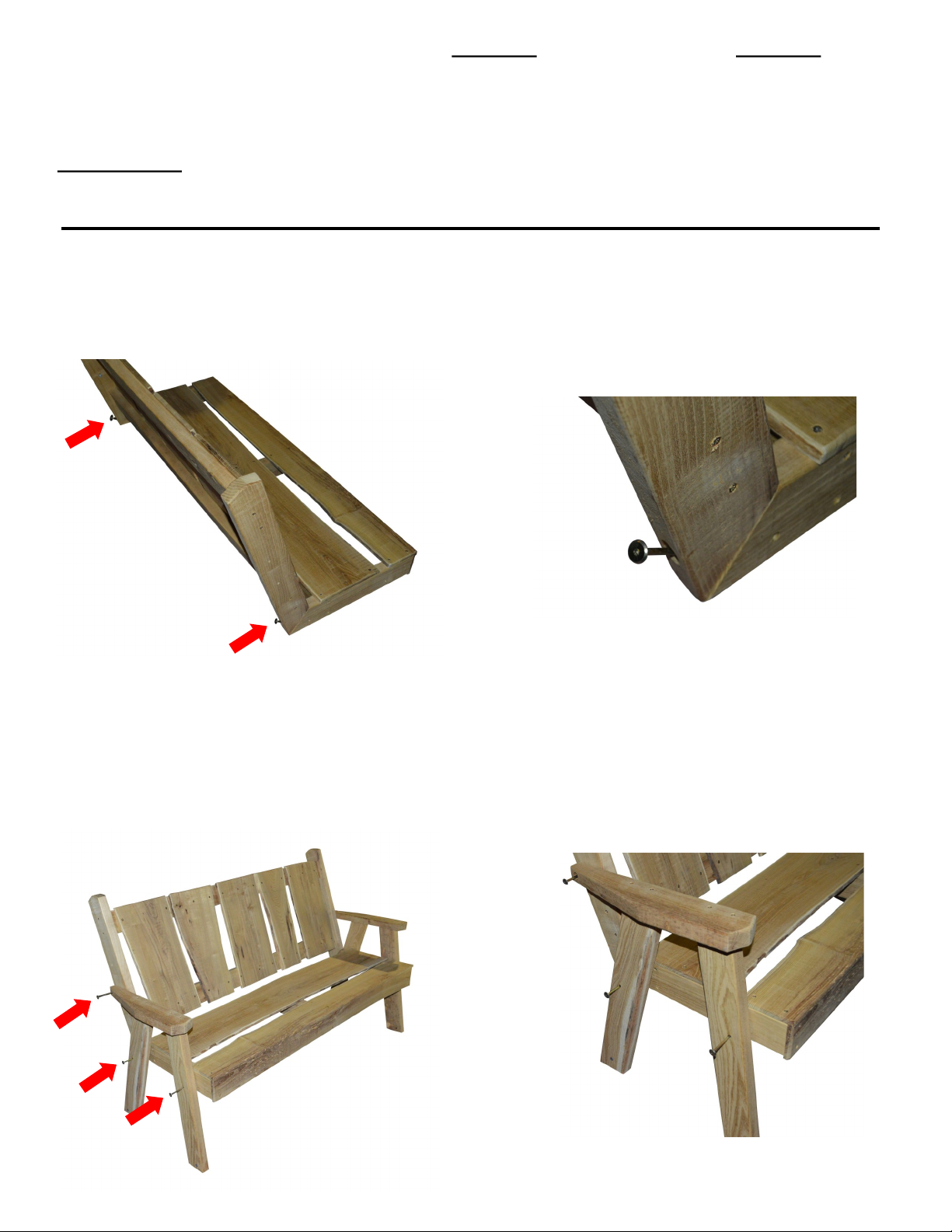
Attach the back assembly to the set assembly. Align the predrilled holes on the bottom of the back side
pieces with the threaded inserts on the back of the seat. Attach with two 3½” bolts. (See photos 1 & 2.)
NOTE: Do not fully tighten these bolts until Step 2 is completed.
photo 1
photo 2
Step 2
Attach the right & left arm & leg assemblies as shown. Align the two predrilled holes in the legs with the
threaded inserts in the side of the seat & fasten with two 3½” bolts. Align the hole in the back of the arm
with the hole in the side of the back & fasten with a 2¾” bolt. (See photos 3 & 4.) If you have problems
aligning the holes, loosen the bolts that attach the back to the seat. Fully tighten all bolts with the Allen
wrench.
photo 3
photo 4
Page 2
Step 3
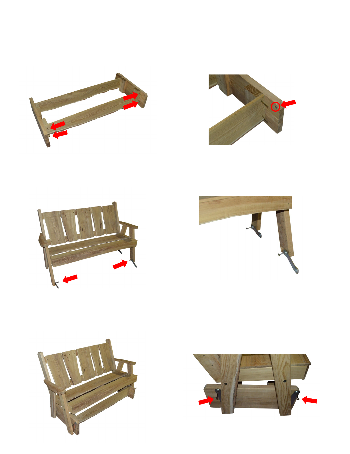
Assemble the glider base. Take the glider feet & set them on the floor. The 2x4 blocks belong on the
inside & the end with the threaded insert close to the front edge belongs on the front. Take the glider
braces and attach to the outside of the 2x4 blocks on the glider feet, one on the front & one on the
back. Place four 1½” screws in the predrilled holes & screw into the blocks. (See photos 5 & 6.)
NOTE: The bark edge on the glider braces must be turned down.
Step 4
Attach the glider hangers to the bottom of the glider legs. Place the hangers on the inside of the legs.
Put a 2” bolt through the hanger & turn into the threaded inserts in the glider legs. Tighten with the Allen
wrench. (See photos 7 & 8.)
Step 5
Now set the glider on top of the base. Attach the other end of the glider hangers to the top of the glider
feet. Put the last four 2” bolts through the hangers & turn into the inserts in the feet. Make sure you
have the base turned correctly with the inserts closest to the front edge of the feet turned toward the
front. (See photos 9 & 10.)
photo 5
photo 6
photo 7 photo 8
photo 10 photo 9
Insert at Edge
turned toward front
 Loading...