

Page 1
ASSEMBLY AND INSTALLATION
INSTRUCTIONS
WARNING: BE SURE TO SHUT OFF POWER AT THE MAIN FUSE OR CIRCUIT
BREAKER BOX BEFORE INSTALLING OR SERVICING THIS FIXTURE.
NOTE: 1. Before installing, consult local electrical codes for wiring and grounding requirements.
2. The combined weight of your ceiling fan and light kit cannot exceed 35 pounds unless
additional support is provided for the fan.
WARNING:
As per EPACT 2005 requirements, this fan light has a built-in
current limiting device to conserve energy. Please do not operate
it with lamps that together consume more than 190 watts. If the
fan light shut off shortly after it was switched on, it may be due to
excessive current demand. Turn off power to the fan and replace
the light bulbs with lower wattage bulbs. Powers up again by pull
chain or wall switch or remote control depend on what is installed
with the particular fan.
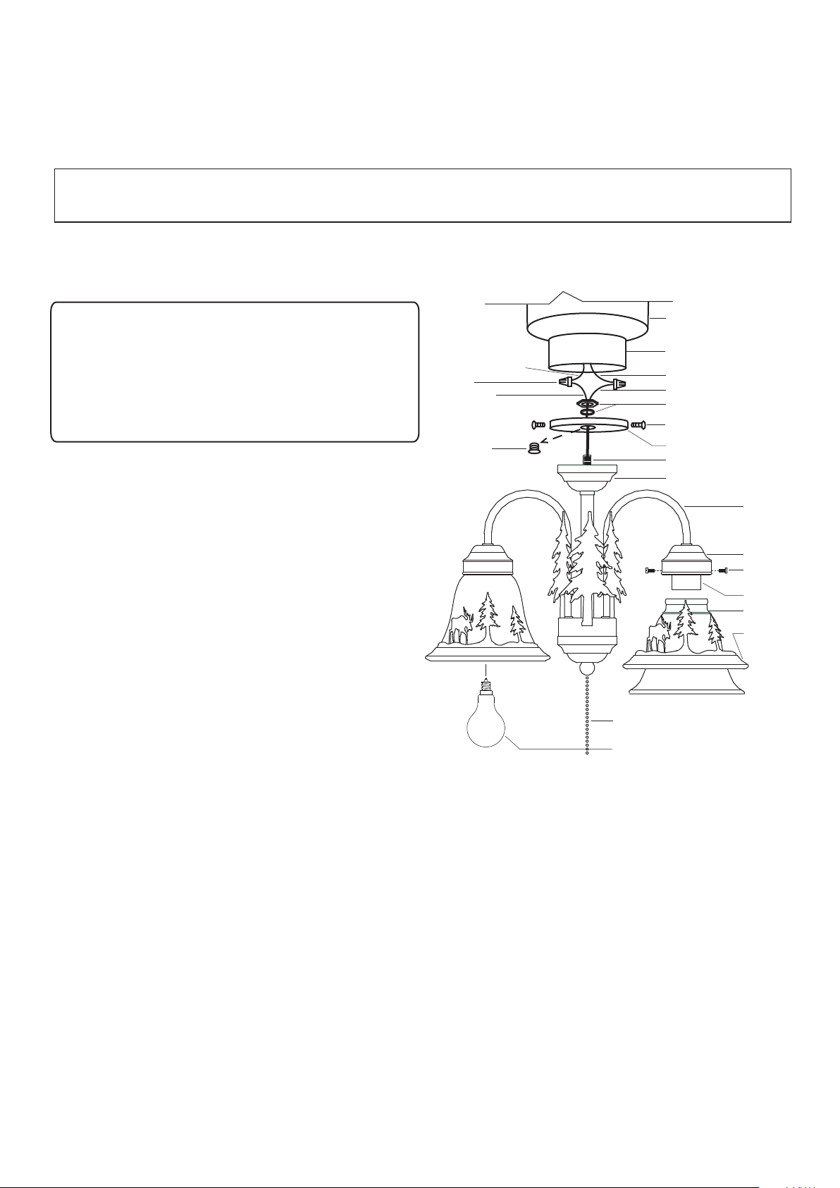
For Light Kit:
1. Remove the switch box cover from
the switch box of the fan by loosing
the three switch box screws.
Black or Blue Wire
Wire Nut
Smooth Wire
Center Plug
Motor
Switch Box
White Wire
Ridged Wire
Hex Nut & Washer
Switch Box Screw
Switch Box Cover
Nipple(-a)
Fixture
Arm
Glass Holder
Set Screw
Socket
Glass Shade
Decoration
2. Unscrew the center plug from the
switch box cover and discard it.
3. Attach nipple(-a) of the light kit to the
switch box cover, then secure it with a
washer and hex nut.
Pull Chain
Bulb Type A15 Max.60W
(included)
4. Pull out the wires from the switch box.
Make wire connections using the wire nuts:
---The smooth (marked) wire from the fixture to the black (or blue) wire from the switch
box.
---The ridged (unmarked) wire from the fixture to the white wire from the switch box.
Carefully put the wires back into the switch box.
5. Attach the switch box cover back to the switch box using the three switch box screws.
6. Carefully place the decorations onto the glass shades. Then attach the glass shades to the
glass holders and secure them with the set screws.
7. Install bulbs (included). See relamping label at socket area or packaging for maximum
allowed wattage.
8. Turn on the power at the main fuse or circuit breaker box. (You can control the light
with the pull chain.)
Page 1 / 2
Page 2
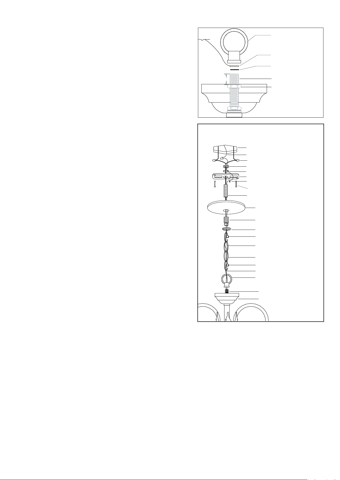
For Mini Chandelier: (See Fig.1 & Fig.2)
1. Take out the loop, grounding pad and washer from
the hardware package for Mini Chandelier.
2. Adjust the hex nut on nipple(-a) to make a length of
1/2" from the top of nipple(-a) to the top of the hex
nut. (See Fig.1)
3. Attach a washer and the grounding pad to the hex
nut on nipple(-a), then secure them with the loop.
4. Choose the length of the chain you need, then
weave the fixture wire and the fixture grounding
wire through the chain. Then connect one end of
the chain with the loop by using one loop lock.
5. Secure the top loop to nipple(-b).
6. Thread the fixture wire and fixture grounding wire
through the collar, canopy, top loop, nipple(-b) and
mounting strap.
7. Connect the other end of the chain with the top loop
by using the other loop lock.
8. Pull out the outlet wires and the house grounding
wire from the outlet box. Make wire connections
using the wire nuts:
---The smooth wire (marked) from the fixture to the
black wire from the power source.
---The ridged wire (unmarked) from the fixture to
the white wire from the power source.
---Attach the fixture grounding wire to the mounting
strap with the green grounding screw. Then
connect it to the house grounding wire with a
wire nut.
Carefully put the wires back into the outlet box.
9. Attach the canopy to the mounting strap by inserting
the top loop, then secure it with the collar.
10. Repeat the steps 6~8 for Light Kit.
Loop
Grounding Pad
Washer
1/2"
Nipple(-a)
Hex Nut
Fig.1
Mounting Parts for Mini Chandelier
Outlet Box
House Grounding Wire
Wire Nut
Hex Nut
Washer
Mounting Strap
Green Grounding Screw
Mounting Screw
Nipple(-b)
Canopy
Top Loop
Collar
Loop Lock
Fixture Grounding Wire
Chain
Loop Lock
Fixture Wire
Loop
Nipple(-a)
Fixture
Fig.2
Page 2 / 2
 Loading...