

Page 1

MA
NUAL
795 BLADE RS
Page 2

EN
CONGRATULATIONS !
IMPORTANT INFORMATION
INTRODUCTION TO THE PRODUCT
PRE-ASSEMBLY CHECK
FULL 795 BLADE RS ROUTING
Rear derailleur hanger
Mechanical/electronic routing conguration
Routing assembly
End cap/guide liner
Hood assembly
Removable hub
Headset
EXPANDER
Expander installation
Expander removal
AEROPOST 2 SEAT POST
INTRODUCTION
Fitting of the SHIMANO battery in the seat post
Fitting the seat post to the frame
Check the seat post is inserted the minimum amount
Cut the AEROPOST 2 seat post
Adjustment of the saddle setback
BRAKE ASSEMBLY
Rear rim brakes
Rear hydraulic brakes
HYDRATION
BOTTOM BRACKET
FITTING THE WHEELS
MAINTENANCE
AFTER SALES SERVICE
GUARANTEE
> 4
> 4
> 5
> 5
> 5
> 5
> 5
> 6
> 8
> 9
> 10
> 11
> 12
> 12
> 12
> 13
> 13
> 14
> 14
> 15
> 16
> 17
> 17
> 17
> 18
> 18
> 19
> 19
> 19
> 19
> 20
Page 3
795 BLADE RS
Spare parts
H
E
795 BLADE RS RIM:
A
795 BLADE RS DISC:
8
C
795 BLADE RS RIM:
A+B
795 BLADE RS DISC:
7
6
Base version Disc
Chain stay Disc version
3
Fourche version Disc
Fork Disc version
10
11
9
I
D
G
5
4
F
Fig. 1
[ A ] [ B ] [ C ] [ D ] [ E ] [ F ] [ G ] [ H ] [ I ]
Head tube
12
1
2
Fig. 2
Page 4
SM-JC41
MAIN ROUTING OPTIONS
CONFIGURATION A
Frame routing mechanical / rim conguration
3
CONFIGURATION B
Frame routing mechanical / disc conguration
2
Non utilisé dans cette configuration
Not use in this configuration
Dérailleur arrière
1
Rear derailleur
1
Dérailleur avant
2
Front derailleur
Frein arrière
3
Rear brake
CONFIGURATION C
Frame routing electronical / rim conguration
6
3
5
2
1
Jonction B
Jonction A
EW-RS910
4
Non utilisé dans cette configuration
Not use in this configuration
Dérailleur arrière
1
Rear derailleur
Dérailleur avant
2
Front derailleur
Frein arrière
3
Rear brake
Cable de la box de jonction
4
Jonction box cable
Cable de la Baterie
5
Battry cable
Jonction A vers le cintre
6
Jonction A to handlebar
1
Fig. 3
2
2
Sortie à lintérieur de la base gauche
Go out from inside the base
CONFIGURATION D
Frame routing electronic / disc conguration
5
4
3
2
1
Jonction B
Sortie à lintérieur de la base gauche
Go out from inside the base
SM-JC41
1
6
Jonction A
EW-RS910
Non utilisé dans cette configuration
Not use in this configuration
Dérailleur arrière
1
Rear derailleur
Dérailleur avant
2
Front derailleur
Frein arrière
3
Rear brake
Cable de la box de jonction
4
Jonction box cable
Cable de la Baterie
5
Battry cable
Jonction A vers le cintre
6
Jonction A to handlebar
3
Dérailleur arrière
1
Rear derailleur
Dérailleur avant
2
Front derailleur
3
1
Frein arrière
Rear brake
2
Fig. 4
3
1 Rear derailleur
2 Front derailleur
3 Rear brake
4 Junction A-B wire
5 Battery
Junction-A to handlebar
6
Fig. 5 Fig. 6
Page 5
EN
CONGRATULATIONS !
You have chosen the LOOK 795 BLADE RS.
Thank you for putting your trust in our products. By choosing this new LOOK kit, you get the advantages
of a high tech, French designed product.
Your frame and its LOOK peripherals, which are identical to those provided to the big professional teams,
are checked throughout their manufacture and will give you complete satisfaction.
Our products meet and, indeed, exceed the various current European and international standards.
LOOK products are protected by industrial property rights
For more information, please go to www.lookcycle.com/patents
Before rst use, read the whole of the instructions.
Follow all the advice given to get the full benet
of this high quality product.
For the assembly we recommend you go to an
approved LOOK dealer.
LOOK reserves the right to change the product
specications with no prior notice in order to
improve it.
IMPORTANT INFORMATION
For the tting of the AERO DESIGN STEM (ADS)
and the ADH 2 handlebar, please refer to the
specic instructions for those products.
Warning : LOOK products are designed
!
and optimised for use by cyclists weighing
no more than 100 Kg (220.5 lbs). Road bikes are
designed for use only on paved roads where the tires
don't leave the ground. Jumps are not allowed.
Warning about Counterfeit Products :
!
The use of counterfeit products is very
dangerous and may cause you, and others, to have
serious falls, causing serious injury or even death.
Registering your new LOOK bike
The registration of your LOOK bike will make you
one of our preferred customers and also gives
you the lifetime guarantee on your frame and fork
aswell as other services.
For more information on the terms, special
offers and coverage of the online registration,
please visit our website www.lookcycle.com
LOOK WARRANTY POLICY section > ONLINE
PRODUCT REGISTRATION.
NOTE : Your 795 BLADE RS frame is only
compatible with the AERO DESIGN STEM (ADS).
For further information, please visit www.lookcycle.
com LOOK WARRANTY POLICY section >
COUNTERFEIT GOODS.
For further information on IMPORTANT
INFORMATION, please visit www.lookcycle.
com LOOK WARRANTY POLICY section >
IMPORTANT INFORMATION.
If you cannot visit our site, we can provide
a printed copy of our warranty policies
through your dealer.
4
Page 6

INTRODUCTION TO THE PRODUCT FULL ROUTING OF THE 795
EN
Your 795 BLADE RS set has been developed
and designed according to the specications
oftheLOOK design office in order to offer the best
transmission of force and an unequalled steering
precision.
These two characteristics are possible thanks to the
inclusion of components specically designed for
this frame. They are therefore perfectly compatible
with each other, which allows for a more coherent
whole, leading to improved performance.
The 795 BLADE RS therefore includes several worldwide and patented innovations : the 3S DESIGN
(Smooth Swork Seat stays) coupled with BRIDGE
LESS (brake support xed to the frame tube)
Patent No. FR1855814, guarantee the best traction
due to the strut deformation management, which
increases the efficiency of your 795 BLADE RS.
PRE-ASSEMBLY CHECK
Your frame is now delivered with :
• its fork and headset.
• the routing of the derailleur liners for the mounting
of a mechanical groupset.
• the frame case, with the parts needed to adapt
your bike to the electronic, mechanical and Wireless
versions.
Note : Your 795 BLADE RS frame is routed for
a mechanical assembly (black liner under the
bottom bracket).
Rear derailleur hanger :
When tting the rear hanger, tighten the screws
toa torque of 1 Nm. When removing and retting,
put a drop of medium threadlock (LOCTITE 243™
type on each screw.
Routing conguration
mechanical/electronic :
The 795 BLADE RS is tted with end caps which
allow either electronic or mechanical groupsets
to be used. Consult your LOOK dealer for the list
of compatible groupsets.
5
Page 7

EN
ROUTING ASSEMBLY
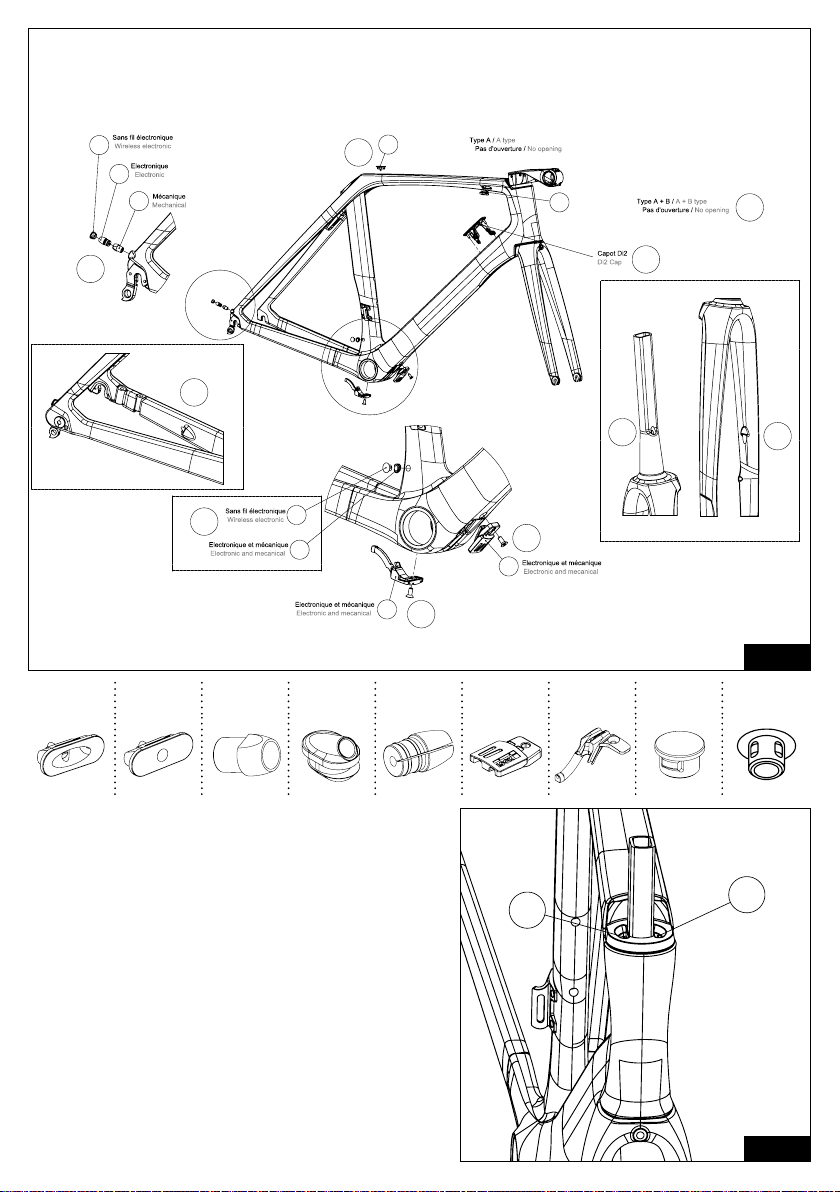
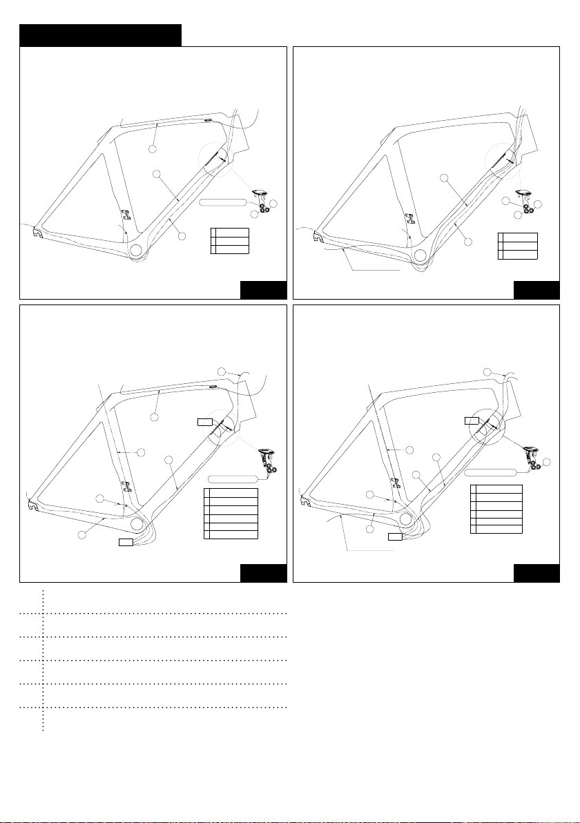
Open the pages for Figures 1-2 at the beginning of the leaet and 3-4-5-6 at the end of the leaet.
MECHANICAL ROUTING CONFIGURATION: A (RIM) AND B (HYDRAULIC)
1 / Remove the derailleur end cap (F) be careful
not to pull on the black liners.
2 / Take two 110 cm derailleur liners, pass one liner into
entrance 2 (g. 2) and the other into entrance 1 (g. 2).
Pass the liners out of opening 4 (g. 1), put a liner cap
on the end of each liner on the bottom bracket end.
3 / Take two 110 cm derailleur liners, pass the
forward derailleur liner into entrance 2 (g. 2) and
the rear derailleur liner into entrance 1 (g. 2). Pass
the liners into the support sheet according to your
conguration (Fig. 3-4-5-6). Pass the liners out
ofopening 4 (g. 1). Thread the two liners through
the foam (long foam tube) for each of the derailleur
liners at exit 4, about 7 cm from the bottom end and
attach adhesive tape.
4 / Before tting the headset, put the foam tubes
(short foam tube) over the tops of the two derailleur
liners.
5 / Pass the rear brake liner or hose (see §.
Hydraulic rear brake) for hydraulic brakes or (see
§ rim rear brake) for rim brakes.
6 / Ret the end cap (F) (see §. End cap / guide
liner section).
7 / If you route your bike for a hydraulic system, then
pass the front brake hose into opening 2 (Fig. 2)
then through entrance 11 (Fig. 1) and nally take it
out at branch 12 (Fig . 1), if the brake caliper hose
is pre-routed then pass through the hole at branch
12 (Fig.1) and out through the fork pivot opening 11
(Fig. 1) then through entrance 2 (Fig. 2). Important:
Before carrying out the following steps you must t
the ADH2 handlebar (recommended) or a handlebar
with a diameter of 31.8 mm and the AERO DESIGN
STEM (ADS). Refer to the relevant instructions.
Important : Before carrying out the following
steps you must t the ADH2 handlebar
(recommended) or a handlebar with a diameter
of 31.8 mm and the AERO DESIGN STEM
(ADS). Refer to the relevant instructions.
8 / Pass the rear derailleur cable from the shifter and
pass it out through exit 6 (g. 1) put the cap (C) and
the liner onto the cable.
9 / Cut the liner at exit 9 (g. 1) to about 5 cm.
10 / Pass the front derailleur cable from the shifter
and pass it out through exit 9 (g. 1) then install
theliner grommet / angled exit wire (D).
11 / Finish the assembly.
Length of foam tubes in the case
Frame size Long foam tube (x3) Short foam tube (x3)
XS 420 mm 110 mm
S 420 mm 120 mm
M 450 mm 130 mm
L 450 mm 140 mm
XL 450 mm 150 mm
6
Page 8

ROUTING ASSEMBLY
ELECTRONIC ROUTING CONFIGURATION: C (RIM) AND D (HYDRAULIC)
EN
1 / Remove the derailleur end cap (F).
2 / Remove the two black mechanical routing liners
by pulling on them.
3 / Route the electronic groupset following the
SHIMANO recommendations.
4 / Connect the junction box (junction A) and
position it on the hood see section (see §. HOOD
ASSEMBLY).
5 / Pass the rear brake liner or hose (see §.
Hydraulic rear brake) for hydraulic brakes or (see
§ rim rear brake) for rim brakes.
6 / Ret the end cap (F) (see §. End cap / guide
liner section).
7 / If you rout your bike for a hydraulic system then
pass the front brake hose through opening 2 (Fig.2)
then through entrance 11 (Fig. 1) and nally pass
WIRELESS ELECTRONIC ROUTING CONFIGURATION: E (RIM) AND F (HYDRAULIC)
1 / Remove the derailleur end cap (F).
2 / Remove the two black mechanical routing liners
by pulling on them.
5 / Pass the rear brake liner (see §. Hydraulic
rear brake) for hydraulic brakes or (see § rim rear
brake) for rim brakes.
4 / Ret the end cap (F) (see §. End cap / guide
liner section).
7 / If you route your bike for a hydraulic system, then
pass the front brake hose into opening 2 (Fig. 2)
then through entrance 11 (Fig. 1) and nally take
itout at branch 12 (Fig. 1), if the brake caliper hose
is pre-routed then pass through the hole at branch
12 (Fig. 1) and out through the fork pivot opening 11
(Fig.1) then through entrance 2 (Fig. 2). Important:
Before carrying out the following steps you must t
itout at branch 12 (Fig . 1), if the brake caliper and
its hose are pre-routed then go through the hole
atbranch 12 (Fig. 1) and exit through the opening of
the fork pivot 11 (Fig.1) then go through entrance2
(Fig. 2).
Important : Before carrying out the following
steps you must t the ADH2 handlebar
(recommended) or a handlebar with a diameter
of 31.8 mm and the AERO DESIGN STEM
(ADS). Refer to the relevant instructions.
8 / Pass the electrical cable (E) through entrance
6 (Fig. 1).
9 / Pass the front derailleur electrical cable and
let it out through exit 9 (Fig. 1) then install the liner
grommet / electrical angled exit wire (D).
10 / Finish the assembly
the ADH2 handlebar (recommended) or a handlebar
with a diameter of 31.8 mm and the AERO DESIGN
STEM (ADS). Refer to the relevant instructions.
Important : Before carrying out the following
steps you must t the ADH2 handlebar
(recommended) or a handlebar with a diameter
of 31.8 mm and the AERO DESIGN STEM
(ADS). Refer to the relevant instructions.
6 / Install the groupset following the manufacturer's
recommendations
7 / Place Ø7.5 plug (H) in entrance 6 (Fig. 1).
8 / Place Ø8 plug (I) in exit 9 (Fig. 1)
9 / Finish the assembly.
7
Page 9
EN
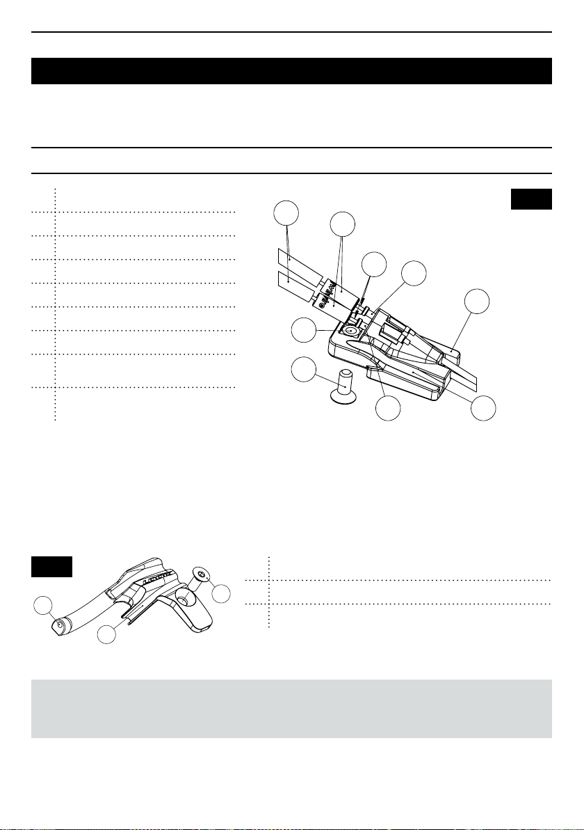
END CAP
1 End cap
2 Rear derailleur liner
3 Front derailleur liner
4 Derailleur cables
5 End caps
6 Derailleur liners
M5 square nut
7
FHC M5x12 Screws - HEX 3mm Allen
8
(tighten to 2 Nm)
Passing the brake liner
9
(hydraulic system)
If you need to replace an end cap the procedure
to use is as follows (the liner is tted before
thehandlebar and the stem).
Fig. 8
1
2
1 Passing rear derailleur liner
2 Passing front derailleur liner
8
8 FHC M5 screw - HEX 3mm Allen ( tightening torque 2 Nm )
6
5
4
2
1
7
8
3
9
1 / Place liners 2 and 3 in the caps in their channels
(Fig. 7)
2 / Place the liners with their caps (Fig. 7)
3 / Tighten the end cap using the FHC M5 x 12
screw, make sure the liners stay properly
positioned in the cap.
Fig. 7
NOTE: the screws 8 are pre-coated with thread lock. Ensure they are not lubricated. after assembling
and disassembling it a few times, it will require a drop of normal thread lock ( LOCTITE 243 ™ type).
8
Page 10
EN
1
5
3
4
2
5
3
4
6
1
5
3
4
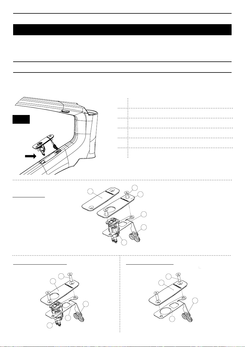
HOOD ASSEMBLY
For a mechanical groupset assembly, this part must remain empty and closed (Fig.9). Do not insert any
food, tools or any other objects that may fall into the frame and seriously disrupt the operation of the bike.
1 Plug cover (mechanical system)
2 Di2 cover (electronic system)
Fig. 9
3 Support sheet
Liner support (x3)
4
5
M4 (x2) 2 Nm screws - HEX 2.5mm Allen
6
SHIMANO box (not included)
Exploded view
SHIMANO Di2 Assembly
2
6
1
5
2
3
4
6
Mechanical assembly
5
4
3
5
1
3
4
9
Page 11
EN
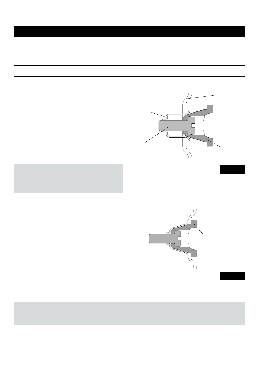
REMOVABLE HUB
ASSEMBLY
1 / Make sure that the end cap is in the open
position.
2 / Place the cap in its housing, against the composite
wall of the frame.
3 / Tighten the tensioner to 1 Nm until
the cap is fully seated in its housing (Fig. 10.1).
WARNING : Excessive tightening of the tensioner
can lead to damage to the screw's thread or to
the retaining spring. The retaining of the cap or its
release may be affected.
DISASSEMBLY
1 / Remove any liner that may be tted into the end cap.
2 / Unscrew the tensioner until the end cap is loose.
3 / Remove the cap. If the cap is reluctant to come
out, unscrew the tensioner some more.
Frame
Retaining
spring
Tensioner
Body of
the end cap
Fig. 10.1
Cap in position
inits housing
CAUTION : The tip of the tensioner is attened to prevent the release of the retaining spring when
loosening, otherwise the tensioning spring may disengage and the threads of the tensioning spring
orthe tensioner may be damaged. The retaining of the cap or its release may be affected.
10
Fig. 10.2
Page 12
EN
4
Version disc /
Disc version
B
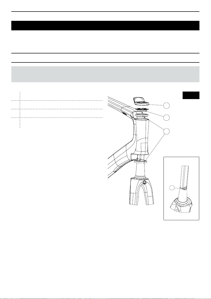
HEADSET
NOTE: For the complete assembly of the LOOK headset, it is highly recommended that you contact your
authorised LOOK dealer.
1 Junction spacer
2 Compression ring
3 1 1/2" (36° - 45°) bearing
Hole for the brake hose
4
(disc version)
1 / Grease the upper seat of your frame and place
abearing 3 (Fig. 11) on this seat.
2 / Grease the lower seat of your frame and fork,
place a bearing 3 (Fig. 11) in the frame taking care
to place the outer chamfer towards the inside of the
head tube then insert your fork into your frame.
3 / Lightly grease the seat of the upper bearing
and slide the compression ring 2 (Fig. 11) onto the
fork up to the upper bearing with the inscription
"FRONT" towards the front of the bike.
4 / Slide the junction spacer 1 (Fig. 11) onto the fork,
then slide it up to the compression ring 2 (Fig. 11).
5 / Move on to the assembly of the AERO DESIGN
STEM (ADS), see the relevant instructions.
1
2
3
Version disc /
4
Fig. 11
Disc version
11
Page 13
EN
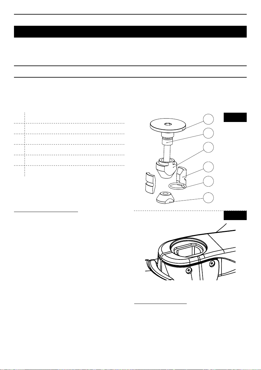
EXPANDER
With your 795 BLADE RS you will nd a factory assembled expander developed specically for the 795
BLADE RS pivot.
1
Cap - HEX 6mm Allen -
2 Fixing screw - HEX 5 mm Allen - 7 to 8 Nm
3 Upper cone
Locking rim (x2)
4
5
O ring
6
Lower cone
max 12 Nm
EXPANDER INSTALLATION
1 / Check that your fork is suitably cut, and that the
cut is between 2 and 5 mm below the support surface
ofyour expander (Fig.13)
2 / Lightly wipe the inside of the fork pivot around
the expander insertion area with a cloth.
3 / Loosen locking screw 2 (Fig. 12), so that the
expander can be slid into the fork pivot without having
to force it.
4 / Lock the expander in the pivot by tightening locking
screw 2 (Fig. 12) with a torque wrench with a 5 mm
Allen head, tighten to a torque of between 7 and 8 Nm.
5 / Limit the play in the steering by tightening cap 1
(Fig. 12), with a torque wrench equipped with a 6 mm
Allen head to a maximum torque of 12 Nm according
to the play to be got rid of.
1
Fig. 12
2
3
4
5
6
Fig. 13
EXPANDER REMOVAL
1 / Unscrew locking screw 2 (Fig. 12) so that the
expander can be removed from the fork.
12
Page 14
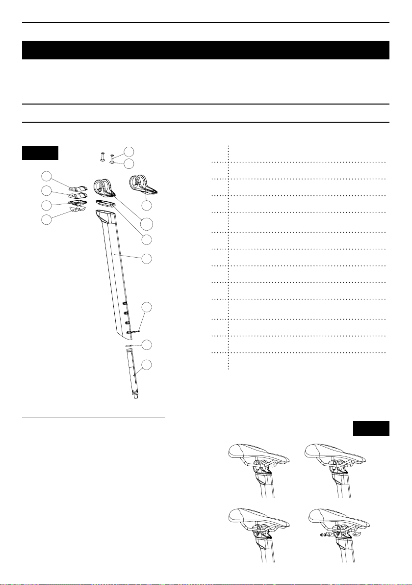
AEROPOST 2 SEAT POST
N°
Désignation
1
Tube de selle AEROPOST 2
2
Elastomère de confort
3
Tête court déport
4
Tête long déport (optionelle)
5
Vis de fixation de tête (x2)
6
Rondelle cuvette sous vis (x2)
7-1
Support supérieur (pour rails de selle ronds)
7-2
Support supérieur (pour rail de selle ovales)
8
Support inférieur
9
Bride et vis inférieurs
10
collier de fixation plastique
11
Joint torique
12
Baterie (non fournie)
EN
Fig. 14
7-1
7-2
8
9
FITTING the saddle onto the seat post
1 / Place the saddle on the head of the AEROPOST 2
2 / Insert the upper bracket bearing the logo " Ø7 "
(Fig. 15) if you want to use a Ø7 round rail saddle or
the bracket marked "Ø OVERSIZE" (Fig. 15) for an
5
6
4
3
2
1
10
11
12
oval rail saddle.
3 / Then insert the lower bracket 8 (Fig. 15) under the
saddle rails.
4 / join the two lower anges and tighten previously
greased screw 10 (Fig. 15) to the indicated torque
of6Nm when your saddle is correctly positioned
1 AEROPOST 2 tube
2 Comfort elastomer
3 Short offset head
Long offset head (optional)
4
Head xing screw (x2) - TORX T25 - 4 Nm +
5
LOCTITE 243™
6
Domed washer for screws (x2)
7-1
Upper support (for round saddle rails)
7-2
Upper support (for oval saddle rails)
8
Lower support
Lower ange and screws - HEX 4 mm Allen - 6 Nm +
9
grease
10
Plastic battery bracket
11
O ring
12
Battery (not supplied in the kit)
The AEROPOST 2 system includes an elastomeric
ring that helps lter road vibrations and provides the
saddle with some give, increasing cycling comfort.
Fig. 15
1 /
3 /
2 /
4 /
13
Page 15
EN
AEROPOST 2 SEAT POST
IMPORTANT: Your AEROPOST 2 seat post is not compatible with oval rail saddles with rails taller
than9.6mm.
REMOVAL of the saddle
To remove the saddle, or to adjust its position : unscrew by a few turns the lower anges' screw. Apply a slight
force to the front and back of the saddle alternately to loosen the anges on the seat post. If they do not loosen
because of heavy tightening, use a small hammer and lightly hit the head of the screw still held by several thread
turns to push the opposite corner.
FITTING of the SHIMANO battery in the seat post
For the electronic system, you should mount the SHIMANO battery in the seat post as follows:
1 / Fit the O ring 11 (Fig. 14) onto battery 12 (Fig. 14) at its recess (on the rear).
2 / slide battery 12 (Fig. 14) into the seat post 1 (Fig. 14).
3 / Take the plastic collar and place it around the notch of the battery and the seat post.
WARNING: The clip of the plastic collar must be inside the seat post, no part of this collar must extend
beyond the outer edge of the post, it must never interfere with the insertion of the seat post into the frame.
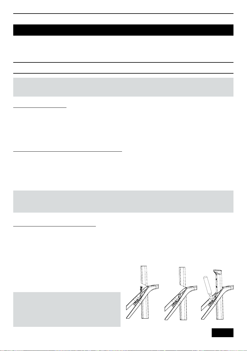
FITTING the seat post onto the frame
Tightening
1 / Make sure that the collet is in the closed position,
that is to say that parts 1 and 2 (Fig. 17) are in contact.
2 / Place the collet in the frame so that the collet lugs
t into the notches in the frame provided for them and
that the collet is properly tted into the hole in the
frame.
3 / Insert your seat post and set the saddle height
youwant.
WARNING: Check that the saddle tube is not
incontact with the upper bottle insert. If it is, cut
the saddle tube (see §. Cutting the AEROPOST
2 seat post).
14
4 / Tighten the seat post using the collet with a torque
wrench tightening it to 10 Nm.
Fig. 16
Page 16
EN
000 20926
AEROPOST 2 SEAT POST
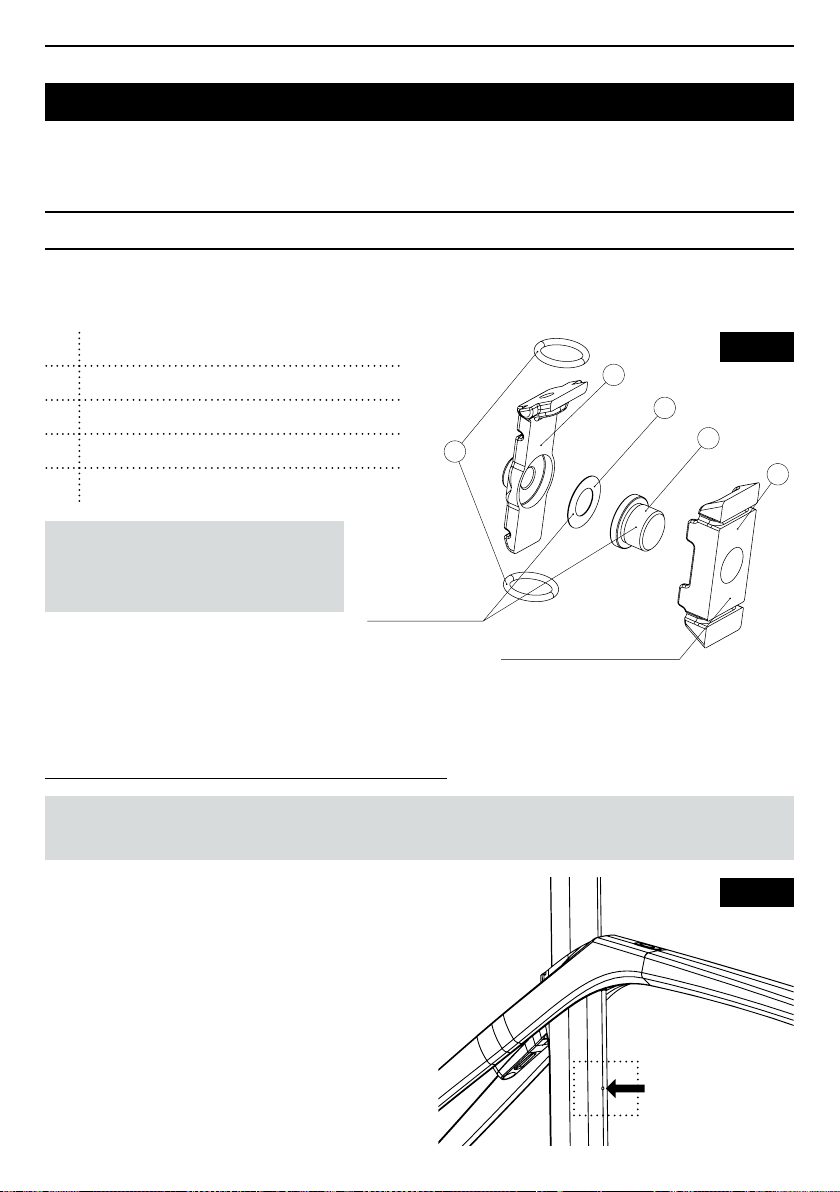
With your 795 BLADE RS you will nd a factory assembled expander developed specically for the 795
BLADE RS pivot.
1 Rear ange
2 Front ange
3 Fixing screw – HEX 4 mm Allen - 10 Nm + grease
O ring
4
5
Washer
1
5
4
Fig. 17
3
2
NOTE : If there is any noise when
tightening or loosening, you should
grease it again.
Graissez les surfaces
Put some grease
Dégraissez les surface de friction
Degrease the friction surface
Loosening / Position adjustment
To disassemble or adjust your AEROPOST 2, unscrew the clamp so that you can slide your seat post without
damaging it, then adjust the position or remove the seat post to disassemble it.
Check the seat post is inserted the minimum amount
IMPORTANT: Take care to ensure the minimum insertion of the seat post in the frame, do this as follows.
1 / Take a 2 mm Allen key and insert it into the hole
located in the saddle tube (Fig. 19)
Fig. 19
OK = Allen key is in contact with the seat post.
Youhave met the minimum insertion requirement
NOK = The Allen key is going into the tube and is not
in contact with the seat post. You have not met the
minimum insertion requirement
15
Page 17
EN
AEROPOST 2 SEAT POST
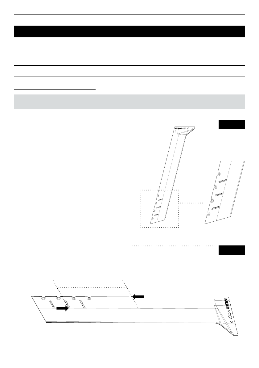
Cutting the AEROPOST 2 seat post
IMPORTANT: Before cutting your seat post, check that the minimum insertion is has been met.
Your AEROPOST 2 seat post gives you the option
to cut it according to the cutting instructions marked
on your seat post (Fig. 18-1), be sure to protect the
surfaces of your seat post to avoid damaging them
during the cutting. Use a cutting tool with a blade for
carbon bre.
Check before cutting :
There must be at least 140 mm between the cut line
and your set position (Fig. 18-2).
1 / Fit your seat post and set the saddle height you
want, lock your seat post.
2 / Note the excess length using the graduated marks
on the front part of the seat post.
3 / Remove your seat post and measure the desired
cutting line to the graduated mark matching your seat
excess length (Fig. 18-1). If this length is less than 140
mm, you must cut on the mark below the chosen one.
L min = 140 mm
Desired cut
Fig. 18-1
Fig. 18-2
Graduated mark matching your
saddle excess length
16
Page 18
AEROPOST 2 SEAT POST
Adjustment of the saddle setback
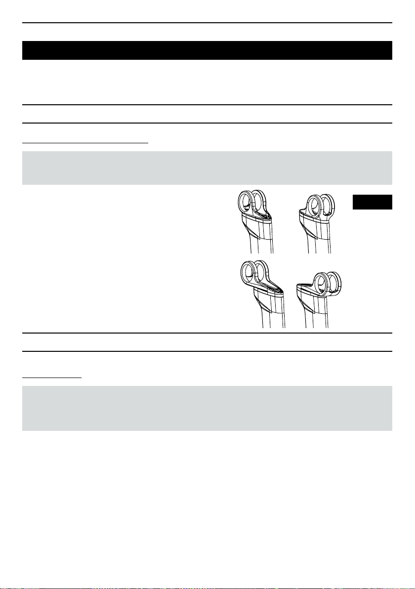
The AEROPOST 2 comes tted with a rearward facing short offset head. If required, you can turn this
part to the front or use the long offset version (not supplied with the bike). To adjust the saddle setback:
EN
1 / remove your saddle from the seat post (see §
Removing the saddle).
2 / Remove the two xing screws 5 and the washers 6
(Fig. 20), then remove the head 3 or 4 (Fig. 20).
3 / Position the head in the desired direction.
4 / Replace the two washers 6 and the two screws 5
adding a drop of LOCTITE 243™ threadlock, tighten
them to a torque of 4 Nm.
5 / ret your saddle onto the seat post (see § Saddle
assembly).
Fig. 20
BRAKE ASSEMBLY
Rear rim brakes
IMPORTANT : For the front brake, as for the rear brake, it is recommended you use the liners supplied.
The use of another type of liner (especially aluminium bead liners, or "more rigid" double-walled liners
is not recommended).
Assembly instructions :
1 / Remove the removable end cap (A) 8 (Fig. 1).
2 / Pass the rear brake liner from the right (EU) or left (UK) lever to the removable cap (A) of entrance 7 (Fig. 1)
(swap caps (A) and (B) for UK routing). Place a liner cap, if your cap has an integrated liner remove it. Make sure
the liner supplied is well seated in its end cap (A).
3 / Thread the rear brake cable and take it out through exit 8 (Fig. 1). Thread the removable end cap (A) onto the
cable at exit 8 (Fig. 1) and x it there.
4 / Place a second piece of the liner with a liner cap in the removable end cap (A) at exit 8 (Fig. 1) up to the
previously tted rear brake.
17
Page 19
EN
BRAKE ASSEMBLY
Rear hydraulic brakes
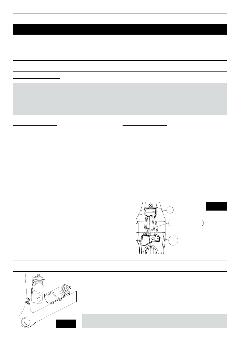
IMPORTANT : There are two assembly options, the rst is an assembly in which the hose is not
connected to the caliper, whereas in the second the hose is pre-connected to the caliper.
NOTE : Your bike in the disc version is provided with 140/160 mm FLAT MOUNT standard compatible
xing front and rear. The thickness of the base at the xing of the rear caliper is 25 mm.
Hose not connected :
1 / Pass the rear brake hose through entrance 1
(Fig.2), then pass it through the support plate (Fig.21),
take the hose out through opening 4 (Fig. 1).
2 / Pass a foam sheath (long foam tube) onto the hose
at its exit through exit 4 (Fig. 1) until it touches with the
support sheet and x it with adhesive tape.
3 / Pass the hose along the routing channel (Fig. 21),
then enter it through opening 5 bis (Fig. 21).
4 / Exit the hose through exit 10 (Fig. 1).
5 / Thread a short foam tube on the brake hose
at the top of the bushing (see § Table of lengths
in chapter Mechanical routing conguration :
A(RIM) and B (HYDRAULIC).
6 / Connect the hose to the caliper.
HYDRATION
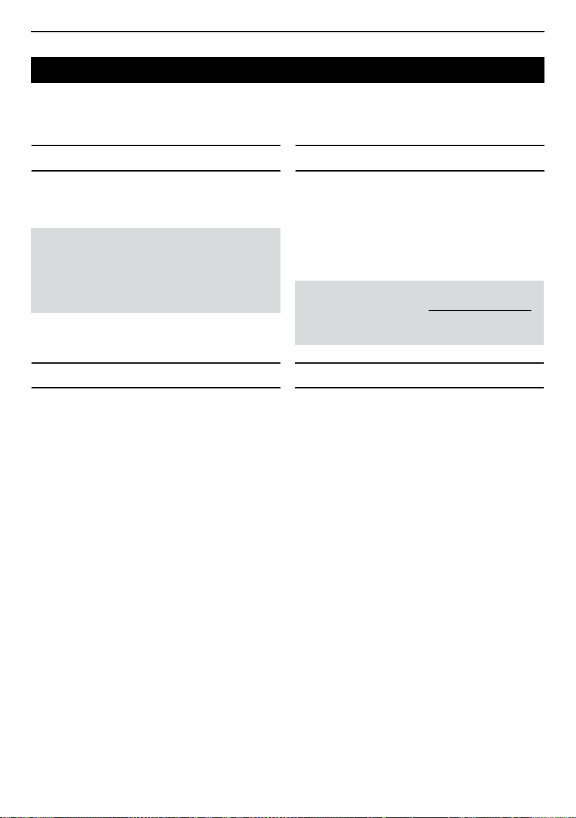
Your 795 BLADE RS is equipped with xings to attach two bottle holders,
one on the saddle tube and one on the diagonal tube (Fig. 22).
Remove the four M5 screws with a 4 mm Allen key. Fit the bottle holders
(refer to the relevant product manual), then tighten the screws to a torque
of 3 Nm.
Hose pre-connected :
1 / Pass the rear brake hose through entrance 10 (Fig. 1),
then take the hose out through opening 5 bis (Fig. 21).
2 / Pass a foam sheath (long foam tube) onto the hose
at its exit through exit 4 (Fig.1) until it touches
the support sheet then x it with adhesive tape.
3 / Pass the hose along the routing channel (Fig. 21),
then enter it through opening 4 (Fig. 21).
4 / Exit the hose through exit 2 (Fig. 2)
4
Canal de routage durite
Brake hose channel routing
5 BIS
Fig. 21
18
Fig. 22
WARNING : Use only the original screws.
Page 20
EN
BOTTOM BRACKET
Your bottom bracket is a PF 386 standard one,
which is 86.5 mm long and has a housing diameter
of 46 mm.
IMPORTANT : For optimal operation LOOK
recommends the tting of a TOKEN box suited
to the standard of your crankset, it is strongly
recommended you go to your nearest LOOK
dealer for more of information.
FITTING THE WHEELS AFTER SALES SERVICE
Follow the manufacturer's assembly instructions.
Ourfork legs are designed with safety lugs. Removing
the safety lugs entails a signicant risk to the bike's
safety that could cause a sudden and catastrophic
failure, resulting in loss of control leading to serious
injury or death.
The 795 BLADE RS in rim version is designed
toaccept wheels with t yre sizes up to 700x28C (metric
measurement) and for the disc version the maximum
diameter is 700x30C (metric measurement).
The standard for xing disc brake wheels uses
traversing axles of MAVIC SPEED RELEASE type :
100mm D12-M12x2-P1 double lead thread thru for
the front wheel and 142mm D12-M12x2-p1 double
lead thread thru for the rear wheel. The MAVIC
SPEED RELEASE READY axles are delivered with
the frame or the bike. We recommend tightening this
axle to 9 Nm and lightly greasing the axle thread.
MAINTENANCE
Checking and maintenance are important for your
safety and the useful life of your product.
Poorly maintained bikes and components can break
or malfunction, which could lead to an accident
in which you could be killed, seriously injured
orparalysed.
For further information on maintenance requirements, please visit www.lookcycle.com
LOOK WARRANTY POLICY section > MAINTENANCE.
In spite of all the care we take during manufacture,
ifa defect appears or if a repair is necessary, contact
your authorized LOOK dealer taking the defective
product to them with your purchase receipt and tell
them about the malfunction.
19
Page 21
EN
GUARANTEE
Statutory guarantee
LOOK, through its authorised agents and distributors
in the country in which the product was purchased,
guarantees its bicycles/frames against faults and
hidden defects (1) for a period of two years (2) from
the date of purchase.
(1) Hidden defects are only covered under French
law. § 1641 to 1649 of the civil code.
(2) Some countries or states allow a longer time
limit for an implicit warranty, and/or for the exclusion
or limitation of direct or consecutive damages
which implies that the limit described above would
not apply. This limited warranty gives you specic
legal rights, but possibly other rights too, which vary
according to local legislation.
For further information on maintenance
requirements, please visit www.lookcycle.com
LOOK WARRANTY POLICY section > LEGAL
WARRANTY.
Lifetime guarantee
The quality and reliability of our products that
we oversee from design to marketing allow us,
through our agents and authorised distributors,
to offer you, in addition to the legally required
guarantees, a free lifetime warranty on LOOK bike
frames and forks.
For further information on maintenance requirements, please visit www.lookcycle.com LOOK
WARRANTY POLICY section > LIFETIME
FRAME WARRANTY.
This manual may not be used or reproduced,
evenpartially, in any form or by any means without
the prior written permission of LOOK.
20
Page 22

Ref. : 00021957
lookcycle.com
 Loading...