

Page 1

MA
NUAL
765 - 765 DISC
Page 2

Page 3

EN
CONGRATULATIONS !
IMPORTANT INFORMATION
INTRODUCTION TO THE PRODUCT
PRE-ASSEMBLY CHECK
FULL ROUTING OF THE 765
Rear derailleur hanger
Mechanical/electronic routing conguration
Removable cap
Mechanical routing assembly
Electronic routing assembly
Wireless assembly
Hydraulic assembly
Headset
BOTTOM BRACKET
FORK
BRAKE
HYDRATION
FITTING THE WHEELS
MAINTENANCE
AFTER SALES SERVICE
GUARANTEE
> 4
> 4
> 5
> 5
> 5
> 5
> 5
> 6
> 8
> 9
> 10
> 10
> 11
> 12
> 13
> 18
> 19
> 19
> 19
> 19
> 20
Page 4

EN
CONGRATULATIONS !
You've chosen the LOOK 765.
Thank you for putting your trust in our products. By choosing this new LOOK kit, you get the advantages
of a high tech, French designed product.
Your frame and its LOOK peripherals, which are identical to those provided to the big professional teams,
are checked throughout their manufacture and will give you complete satisfaction.
Our products meet and, indeed, exceed the various current European and international standards.
LOOK products are protected by industrial property rights
For more information, please go to www.lookcycle.com/patents
Registering your new LOOK bike
Before rst use, read the whole of the instructions.
Follow all the advice given to take full advantage
of this high quality product.
For the assembly we recommend you go to an
approved LOOK dealer.
LOOK reserves the right to change the product
specications with no prior notice in order to
improve it.
The registration of your LOOK bike will make you
one of our preferred customers and also gives you
the lifetime guarantee on your frame and fork as
well as other services.
For more information on the terms, special offers
and coverage of the online registration, please
visit our website
www.lookcycle.com LOOK WARRANTY
POLICY section > ONLINE PRODUCT
REGISTRATION.
IMPORTANT INFORMATION
Warning : The LOOK 765 and 765 DISC
!
products are designed and optimised for use
by cyclists weighing no more than 100 kg (220.5 lbs).
Road bikes are designed for use only on paved roads
where the tires don't leave the ground. Jumping is
not allowed.
Warning : The LOOK 765 and 765 DISC may
!
be clamped in an assembly stand with care.
Warning about Counterfeit Products :
!
The use of counterfeit products is very
dangerous and may cause you, and others, to have
serious falls, causing serious injury or even death.
4
For further information, please visit
www.lookcycle.com LOOK WARRANTY
POLICY section > COUNTERFEIT GOODS.
For further details on IMPORTANT INFORMATION, please visit www.lookcycle.com LOOK
WARRANTY POLICY section > IMPORTANT
INFORMATION.
If you cannot visit our site, we can provide
a printed copy of our warranty policies
through your dealer.
Page 5

INTRODUCTION TO THE PRODUCT FULL ROUTING OF THE 765
Your 765 or 765 DISC set has been designed
and developed following the LOOK design office
specications to provide a comfortable riding
position thanks to its Endurance geometry as well
as a structure made of carbon bre mixed with
natural ax bres to better lter out the vibrations
on long trips.
This result is achieved by using a "sandwich"
structure to allow the Flax Fibres to work between
two layers of carbon bre. This is done to optimise
the performance and the ltering out of vibrations.
PRE-ASSEMBLY CHECK
Your frame is now delivered with :
• its fork and headset.
• the routing of the derailleur liners for the mounting
of a mechanical groupset.
• the aluminium version of its collar (6 Nm max).
• The LOOK pouch with the optional ttings (end caps).
Note : Your 765 frame is routed for a mechanical
assembly (black liner under the bottom bracket).
Rear derailleur hanger :
When tting the rear hanger, tighten the screws to
a torque of 1 Nm. When removing and retting, put
a drop of medium threadlock (LOCTITE 243™ type
on each screw.
Mechanical/electronic routing conguration :
The 765 is tted with end caps which allow either
electronic or mechanical groupsets to be used.
Consult your LOOK dealer for the list of compatible
groupsets.
Note : The 765 is compatible with the Campagnolo
EPS V2 groupset, to t this groupset please refer
to the manufacturer's recommendations.
EN
5
Page 6
EN
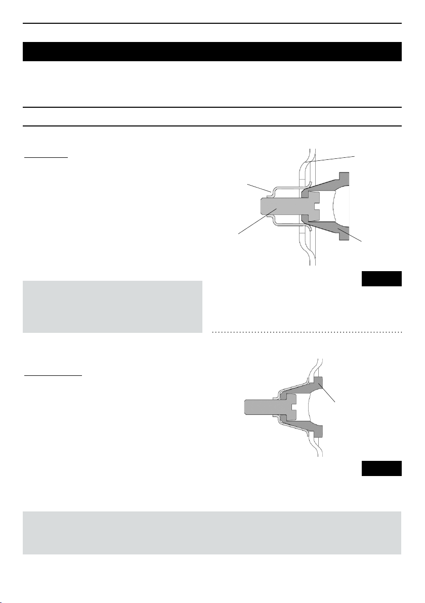
REMOVABLE CAP
ASSEMBLY
1 / Make sure that the end cap is in the open position.
2 / Place the cap in its housing, against the composite
wall of the frame.
3 / Tighten the tensioner to 1 Nm until
the cap is fully seated in its housing (Fig. 10.1).
WARNING : Excessive tightening of the tensioner
can lead to damage to the screw's thread or to
the retaining spring. The cap retention or its
release may be affected.
DISASSEMBLY
1 / Remove any liner that may be tted into the
end cap.
2 / Unscrew the tensioner until the end cap is loose.
3 / Remove the cap. If the cap is reluctant to come
out, unscrew the tensioner some more.
Frame
Retaining spring
Tensioner
End cap body
Fig. 10.1
Cap in position
in its housing
CAUTION : The tip of the tensioner is attened to prevent the release of the retaining spring when
loosening, otherwise the tensioning spring may disengage and the threads of the tensioning spring or
the tensioner may be damaged. The cap retention or its release may be affected.
6
Fig. 10.2
Page 7
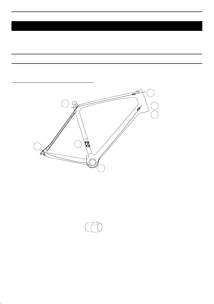
ROUTING ASSEMBLY
A
C2
E
D
F
C1
B
Left/left
Right/Right
MECHANICAL ROUTING CONFIGURATION
EN
1 / Check the 2 black liners are in the diagonal tube.
2 / Check the 2 metal end caps are at the
TD entrance towards the head tube (C1 & C2).
3 / Check there are 2 other end caps on the 2 holes
A, B. Then put the small black rear cap on point D
(accessories bag).
4 / Put the two derailleur cables in the 2 black liners.
Left hole C1 = front derailleur, Right hole C2 = rear
derailleur. The 2 cables thread the liners and come
out at point F. The front cable will then come out to
join point E. The rear cable will enter the right rear of
the base and come out at point D.
5 / For the rear brake cable, remove the rear end stop
from the horizontal tube and then thread the rear
brake cable through this tube so it comes out at point
A, then replace the metal end stop at each end.
6 / You have the option to t a front derailleur
tensioner, to do this, cut your front derailleur liner
about 3 cm from the tube exit, then t the tensioner.
Pass the rear derailleur cable from the shifter and
bring it out behind the bottom bracket.
7 / Check the bottom bracket cable guide is tight.
7
Page 8
EN
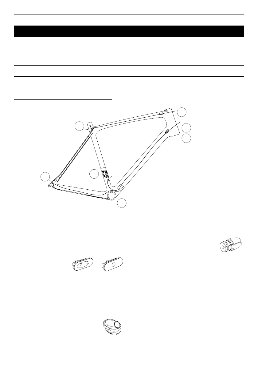
A
C2
E
D
F
C1
B
Left/left
Right/Right
ROUTING ASSEMBLY
ELECTRONIC ROUTING CONFIGURATION
1 / Check the 2 black liners are in the diagonal tube.
2 / Remove these 2 black liners with the 2 metal end
caps C1 & C2.
3 / See the Shimano Di2 instructions.
4 / Put the end cap plug in the housing on the left of
the frame at point C1.
5 / Put end cap Di2 in front of the housing on the
right side of the frame at point C2 and place the
Shimano electronic cable from the tube to the bottom
bracket, then assemble the cap in the housing and
add the Shimano Di2 split cap on the right side
(the magnetic ParkTool, Ref. IR-I, may be used).
8
6 / Similarly in the base pass the Shimano electronic
cable from the derailleur hanger D to the bottom
bracket F, then place split plug Di2 at point D (the
magnetic ParkTool, Ref. IR-I, may be used).
7 / Place the Shimano electronic cable in the saddle
tube from point E to bottom bracket D.
8 / After connecting the wires to the Shimano box,
put the box in the bottom bracket and push it into
the frame.
9 / For the rear brake cable, remove the rear end
cap from the horizontal tube then place the rear
brake cable in this tube and bring it out at point
A, then replace the metal end caps at both ends.
10 / You have the option to t a front derailleur
tensioner, to do this, cut your front derailleur liner
about 3 cm from the tube exit, then t the tensioner.
Pass the front derailleur cable from the shifter and
pass it out.
Page 9
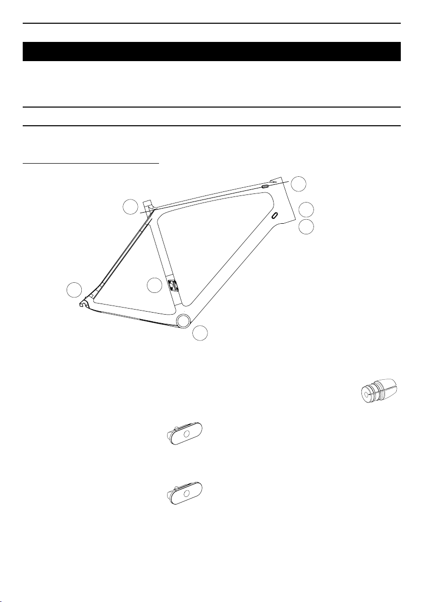
WIRELESS ELECTRONIC ROUTING
A
C2
E
D
F
Left/left
Right/Right
C1
B
EN
ROUTING ASSEMBLY
1 / Check the 2 black liners are in the diagonal tube.
2 / Remove the 2 black liners with the 2 metal
end caps.
3 / See the SRAM ETAP instructions.
4 / Hole left of end cap C1 plug to be placed directly
into the left side of the frame.
5 / Hole right of end cap C2 rubber plug to be placed
directly into the right side of the frame.
6 / Hole rear derailleur hanger plug to be placed
directly into the frame at D.
7 / Check there is a plug at E.
8 / For the rear brake cable, remove the rear end
cap from the horizontal tube then place the rear
brake cable in this tube and bring it out at point
A, then replace the metal end caps at both ends.
9
Page 10
EN
B
A
C
D
E
F
G
B
A
B
A
765 DISC HYDRAULIC ROUTING
ROUTING ASSEMBLY
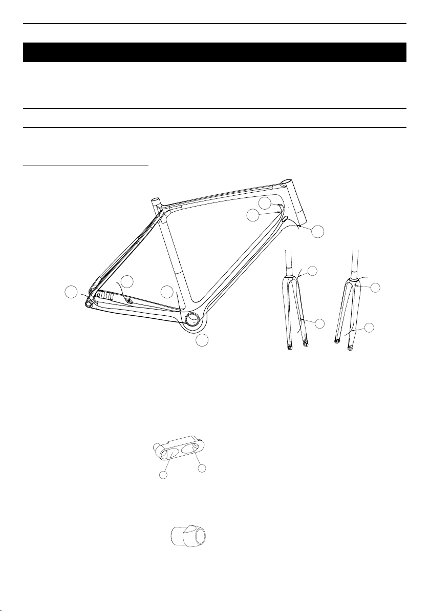
1 / Check the 2 black liners are in the diagonal tube.
2 / Check the 2 metal end caps are at the TD
entrance towards the head tube. On the left side
a new double cap allows Hydraulic brake liner
A and front derailleur liner B to pass as shown below.
On the right side at C is the mechanical cap for the
rear derailleur cable.
A
3 / Check that the small black rear cap is at point G
(if not, it is in the accessories bag)
10
4 / Pass the hydraulic liner from point A to point F,
passing successively through the diagonal tube,
over the bottom bracket and then into the left of
the base and on to the outlet (guide tube without
the frame)
5 / Pass the two derailleur cables through the 2 black
liners. Left hole B rear derailleur. The 2 cables thread
the liners and come out at point F. The front cable will
then come out to join point E. The rear cable will enter
the right rear of the base and come out at point G.
B
6 / You have the option to t a front derailleur
tensioner, to do this, cut your front derailleur liner
about 3 cm from the tube exit, then t the tensioner.
Pass the rear derailleur cable from the shifter and
bring it out behind the bottom bracket.
7 / Check the bottom bracket cable guide is tight.
8 / Finish the assembly with the routing of the fork.
This consists of an upper entry A and a lower one B,
to connect to the front brake caliper.
Page 11
EN
Headset
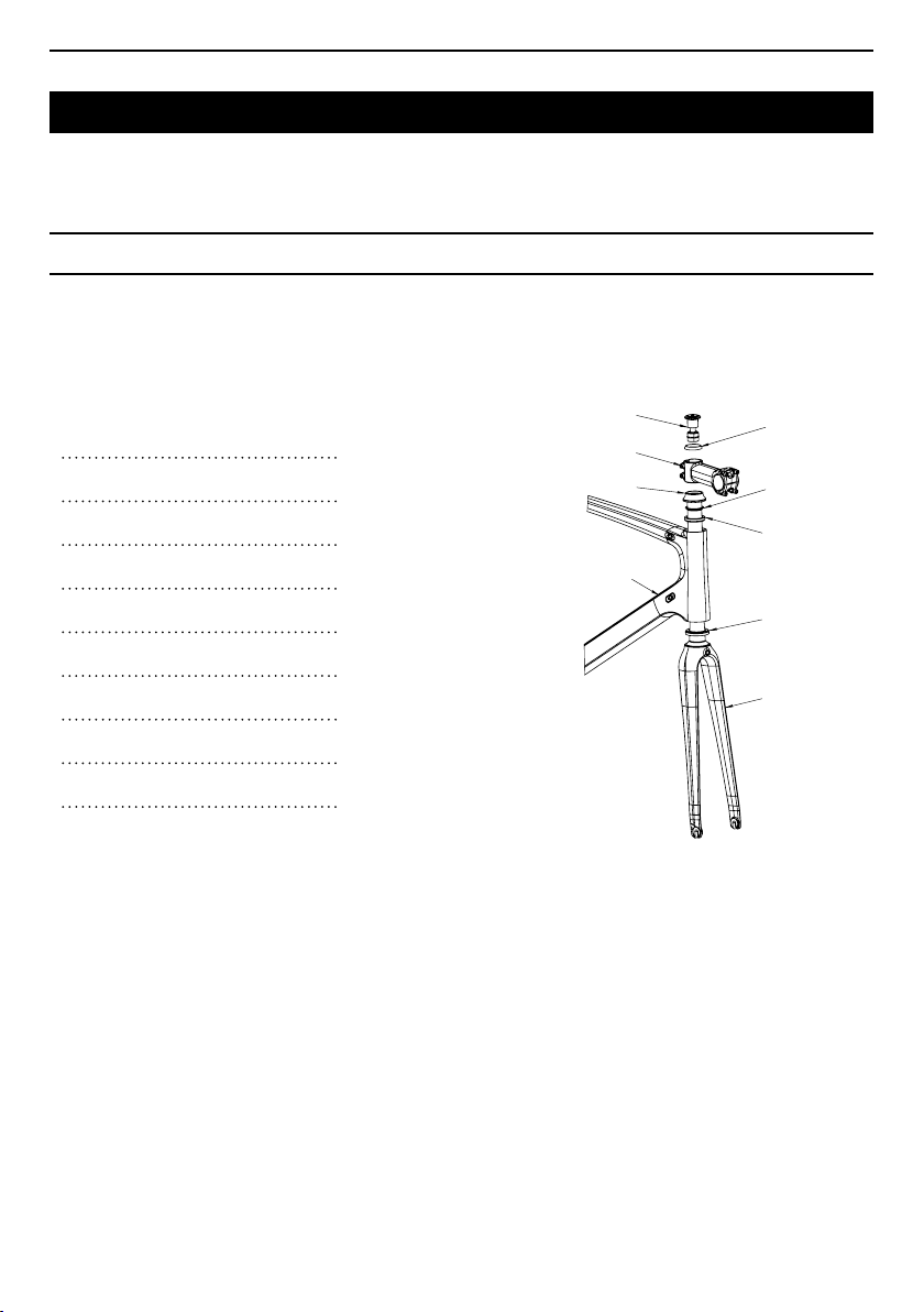
The LOOK 765 headset is a traditional play take-up system with a compression kit. It is always best to place
the upper conical washer over the stem to avoid clamping the stem at the end of the pivot. This is in order
to reduce the long term risk of the carbon structure cracking.
[ 1 ] Compression kit
[ 2 ] Upper conical washer
[ 3 ] Traditional stem
[ 4 ] JDD Spacer
[ 5 ] Compression split ring
[ 6 ] Upper 1 1/8" bearing
Frame with carbon seating
[ 7 ]
[ 8 ]
Lower 1 1/4" bearing
[ 9 ]
Monobloc fork
1 / Grease the upper seating of your frame and
place the upper 1 1/8" bearing on this seat.
2 / Grease the lower seating of your frame and fork,
place the lower 1 1/4" bearing in the frame taking
care to place the outer chamfer towards the inside of
the head tube then insert your fork into your frame.
[ 1 ]
[ 3 ]
[ 4 ]
[ 7 ]
[ 2 ]
[ 5 ]
[ 6 ]
[ 8 ]
[ 9 ]
3 / Slide the compression ring on the fork up to the
upper bearing.
4 / Slide on the stem.
6 / Position the upper conical washer and then the
compression kit.
7 / Tightening of the compression kit in the fork's
pivot (6 Nm max) then adjust the headset.
11
Page 12
EN
BOTTOM BRACKET
The LOOK 765 frames are delivered with a PRESS
FIT BB30 type bracket of 46 mm diameter and
68 mm length.
BRAKE ASSEMBLY
This is a standard brake assembly on fork and
struts, the only specication specic to this frame
is the recommended placement of the black foam
tube, around the rear brake cable in the horizontal
tube, to limit any noise from vibration in the frame
(XS L500mm, L520mm S, M L550mm, L 565mm,
XL 580mm).
FORK
The 765 forks are differentially offset to match all
frame sizes and better suit practical competition
cycling (XS S 50mm, M L XL 43mm).
The prole and the carbon structure have been
thoroughly studied to provide one of the best blends
of precision, weight and rigidity on the market.
Note: For all maintenance operations, remember
that the fork must be placed on a wheel and any
abnormal wear of the legs from abrasion on the
ground is not covered by the LOOK guarantee.
Warning: The forks are not supplied tted to the
frames with a longer pivot. You will have to cut
the fork pivot to suit your adjustments.
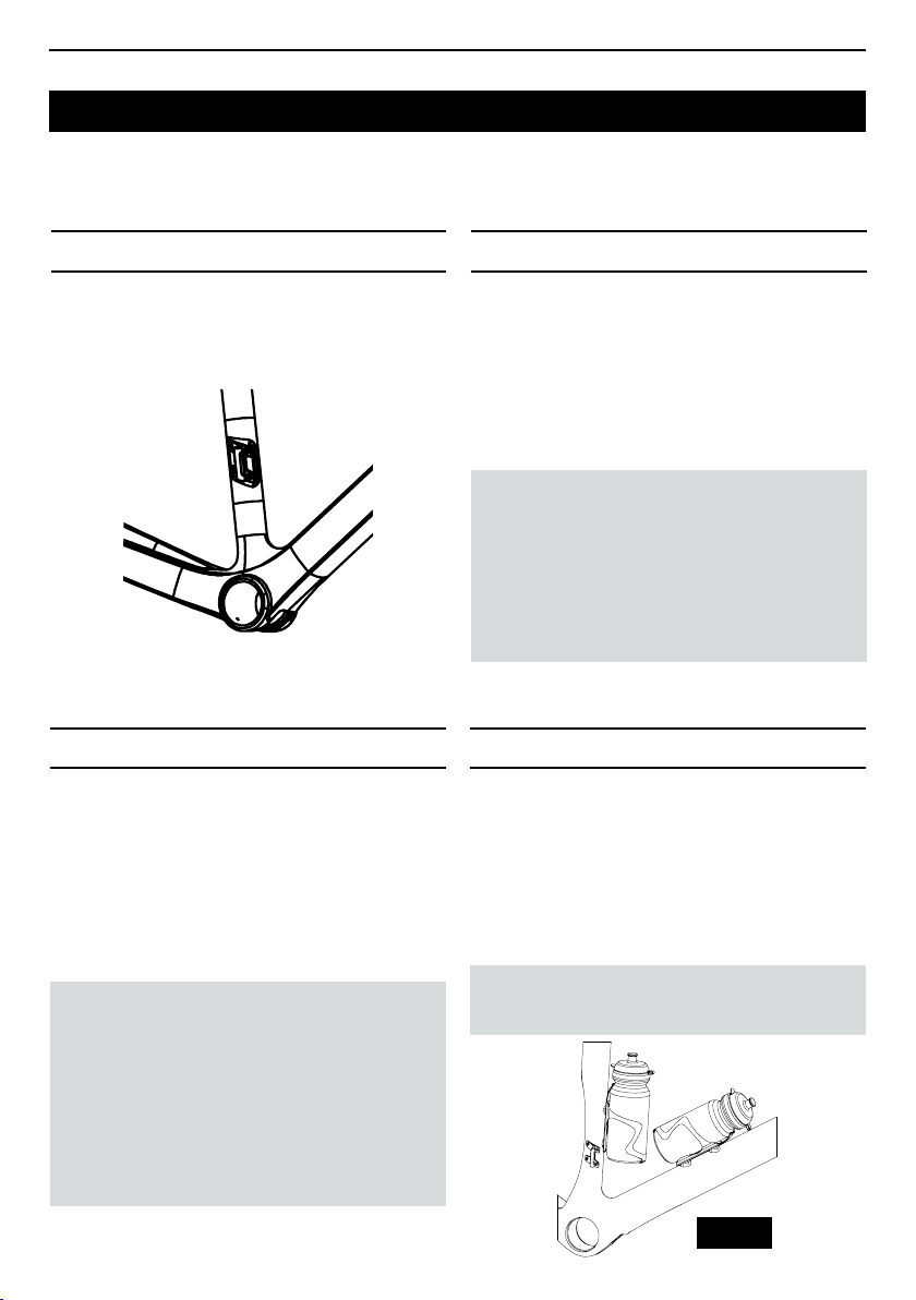
HYDRATION
Your 765 frame comes with inserts to attach two
bottle holders, one on the saddle tube and one on
the diagonal tube (Fig. 28).
Remove the four M5 screws with a 4 mm Allen key.
Fit the bottle holders (refer to the relevant product
manual), then tighten the screws to a torque of 3 Nm.
To assemble the brakes, you will need the
following tools :
• Set of Allen keys
• Cutting pliers
• Liner caps
• Cable caps
12
WARNING : It is advisable to use only the
original screws.
Fig. 28
Page 13
FITTING THE WHEELS
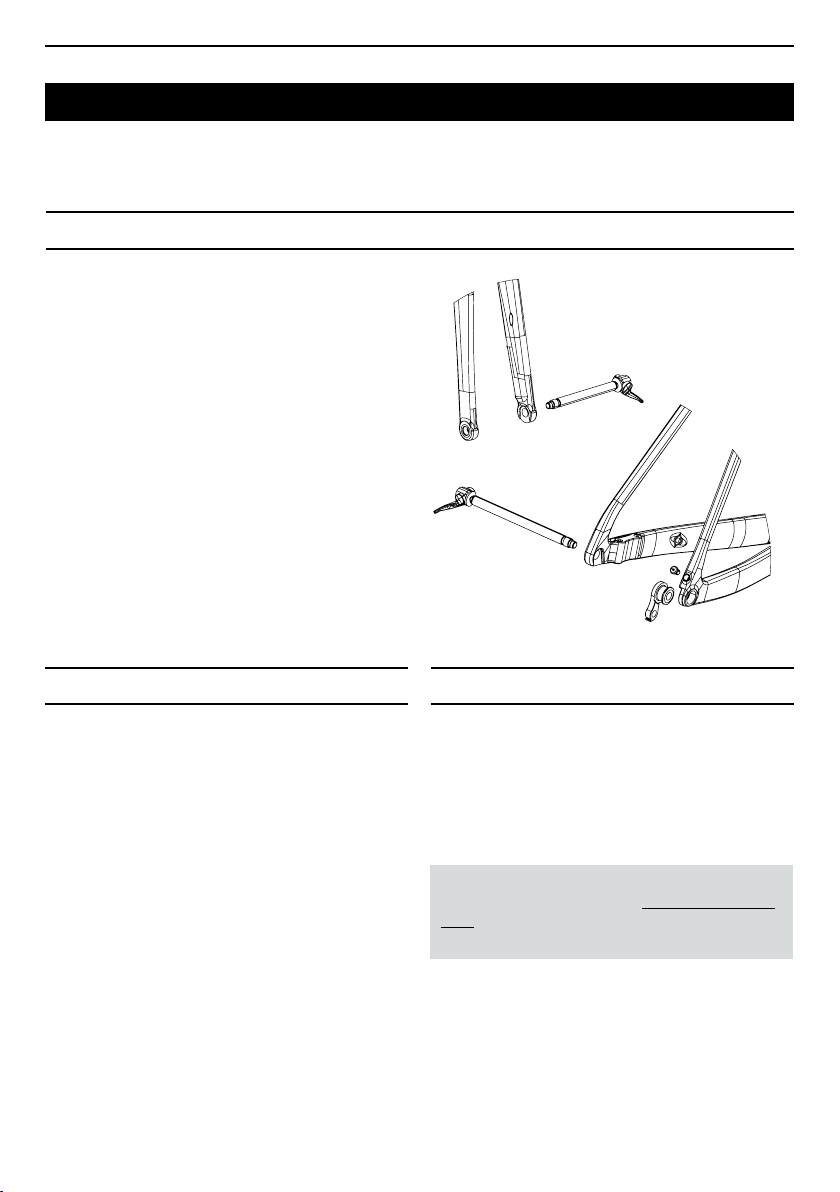
Follow the manufacturer's assembly instructions.
Our fork legs are designed with safety lugs.
The 765 disc fork uses a through axle: Assembly and
complete unscrewing of the Shimano M12*100mm
standard axle to release the front wheel.
The 765 disc fork uses a through axle: Assembly and
complete unscrewing of the Shimano M12*100mm
standard axle to release the front wheel.
The 765 disc rear hanger can be dismantled using
a 22 mm hex nut (recommended tightening torque
3 Nm).
EN
AFTER SALES SERVICE
In spite of all the care we take during manufacture,
if there is a aw or if a repair is necessary, contact
your authorised LOOK dealer, taking the defective
product to them with your purchase receipt and tell
them about the problem.
MAINTENANCE
Checking the state and maintenance are important
for your safety and the useful life of your product.
Poorly maintained bikes and components can break
or malfunction, which could lead to an accident
in which you could be killed, seriously injured
or paralysed.
For further information on maintenance
requirements, please visit www.lookcycle.
com LOOK WARRANTY POLICY section >
MAINTENANCE.
13
Page 14

EN
GUARANTEE
Statutory guarantee
LOOK, through its authorised agents and distributors
in the country in which the product was purchased,
guarantees its bicycles/frames against faults and
hidden defects (1) for a period of two years (2) from
the date of purchase.
(1) Hidden defects are only covered under French
law. § 1641 to 1649 of the civil code.
(2) Some countries or states allow a longer time
limit for an implicit warranty, and/or for the exclusion
or limitation of direct or consequent damages
which implies that the limit described above would
not apply. This limited warranty gives you specic
legal rights, but possibly other rights too, which vary
according to local legislation.
For further information on maintenance
requirements, please visit www.lookcycle.com
LOOK WARRANTY POLICY section > LEGAL
WARRANTY.
Lifetime guarantee
The quality and reliability of our products, which we
oversee from design to marketing, allow us, through
our agents and authorised distributors, to offer you,
in addition to the legally required guarantees, a free
lifetime warranty on LOOK bike frames and forks.
For further information on maintenance requirements, please visit www.lookcycle.com LOOK
WARRANTY POLICY section > LIFETIME
FRAME WARRANTY.
This manual may not be used or reproduced, even
partially, in any form or by any means without the
prior written permission of LOOK.
14
Page 15

lookcycle.com
 Loading...