


H100LonWorksManual
1
Thank you for purchasing LONWORKS Option Board.
SAFETY PRECAUTIONS
Always follow safety instructions to prevent accidents and potential hazards from occurring.
Safety precautions are classified into “WARNING” and “CAUTION” and their meanings are as follows:
WARNING
CAUTION
The indicated illustrations on the product and in the manual have the following meanings.
Danger may be present. Read the message and follow the instructions carefully.
Particular attention should be paid because danger of an electric shock may be present.
Keep operating instructions handy for quick reference.
Read the operating instructions carefully to fully understand the functions of the H100 series and to use it properly.
CAUTION
Be cautious, when handling the CMOS components of the Option Board.
Static may lead to malfunctioning of the product.
Turn off the inverter power, when changing the communication cable.
Otherwise, you may damage the board or a communication error may occur.
Make sure to insert the Option Board connector to the inverter precisely.
Otherwise, you may damage the board or a communication error may occur.
Check the parameter unit before setting up the parameter.
Otherwise, a communication error may occur.
Improper operation may result in serious personal injury or death.
Improper operation may result in slight to medium personal
injury or property damage.

H100LonWorksManual
2
1. Introduction
1.1 About the LonWorks (Local Operating Network) Platform
The LonWorks is a networking platform created by Echelon Corporation, which is widely utilized in the field of
building automation. On a LonWorks network, all the devices connected to the network nodes can freely
communicate with each other using the LoneTalk protocol. There is no distinction between ‘the master’ and ‘the slave’
devices. Devices connected to the LonWorks network are manufacturer-independent. This independence is achieved
by the use of the standard network variable types (SNVT). The H100 communication module supports these standard
network variable types. Using the standard network variable types, automated data communication becomes
available at the initial installation of the devices. This is done by configuring the input and output variables with an
installation tool. When configuring the input and output variables of the devices, the network variable types used
must always match.
1.2 The H100 LonWorks Communication Module Features
The H100 LonWorks communication module provides control and monitoring for inverters. The LonWorks platform
allows the connection of multiple inverters to a single line, thus saving on the expenses of network implementation.
Also, the LonWorks network features simple wiring, which allows for decreased installation time and easier
maintenance.
1.3 The H100 LonWorks Communication Module - Model Name
Model Name: CLON-H100
1.4 Included Items
The H100 communication module comes with the following items.
- H100 LonWorks communication module x 1EA
- H100 LonWorks user manual x 1EA
- Screws (M3xL08) x 2EA
- 3-Pin connector (PTR AK 950/03-5.0-GREEN) x 1EA
- Module supporter x 1EA

H100LonWorksManual
3
2. About The H100 Lon Works Communication Module
2.1 Technical Data
Items
Description
Power
Power supply to the H100 LonWorks
communication module
Power is supplied by the inverter(s)
Network Topology
Free Topology
(Bus, Star, Loop, or any combination of these 3 types)
Baud Rate
78 Kbit/s
LonWorks Communication Chipset
FT3150-P20 chip (Echelon)
LonWorks Transceiver
FT-X1
Data Networking Type
Peer-to-peer
Channel Type
TP/FT-10
Transfer Cable
Free Topology Twisted Pair
Maximum Number of Nodes
Maximum 2
48
nodes (48bit addressing)
64 channels per segment (including the Master)
Maximum Transfer Distance per Segment
Free Topology : 500m
Bus Topology : 2700m
Available PDO (Physical Device Object)
Node Object
Variable Speed Motor Object(6010)1
User Object(20001, User Function Profile Type)2
LonWorks Connector
Plug-in Connector
Terminal Resistance
Free Topology : 50Ω
Bus Topology : 100Ω
Built-in terminal resistance (switch on the module for topology
selection)
1
Variable Speed Motor Object (6010) is a universally compatible object throughout all manufacturers.
2
User Object is a manufacturer-defined object whose flexibility is dependent upon the manufacturer design.
H100LonWorksManual
4
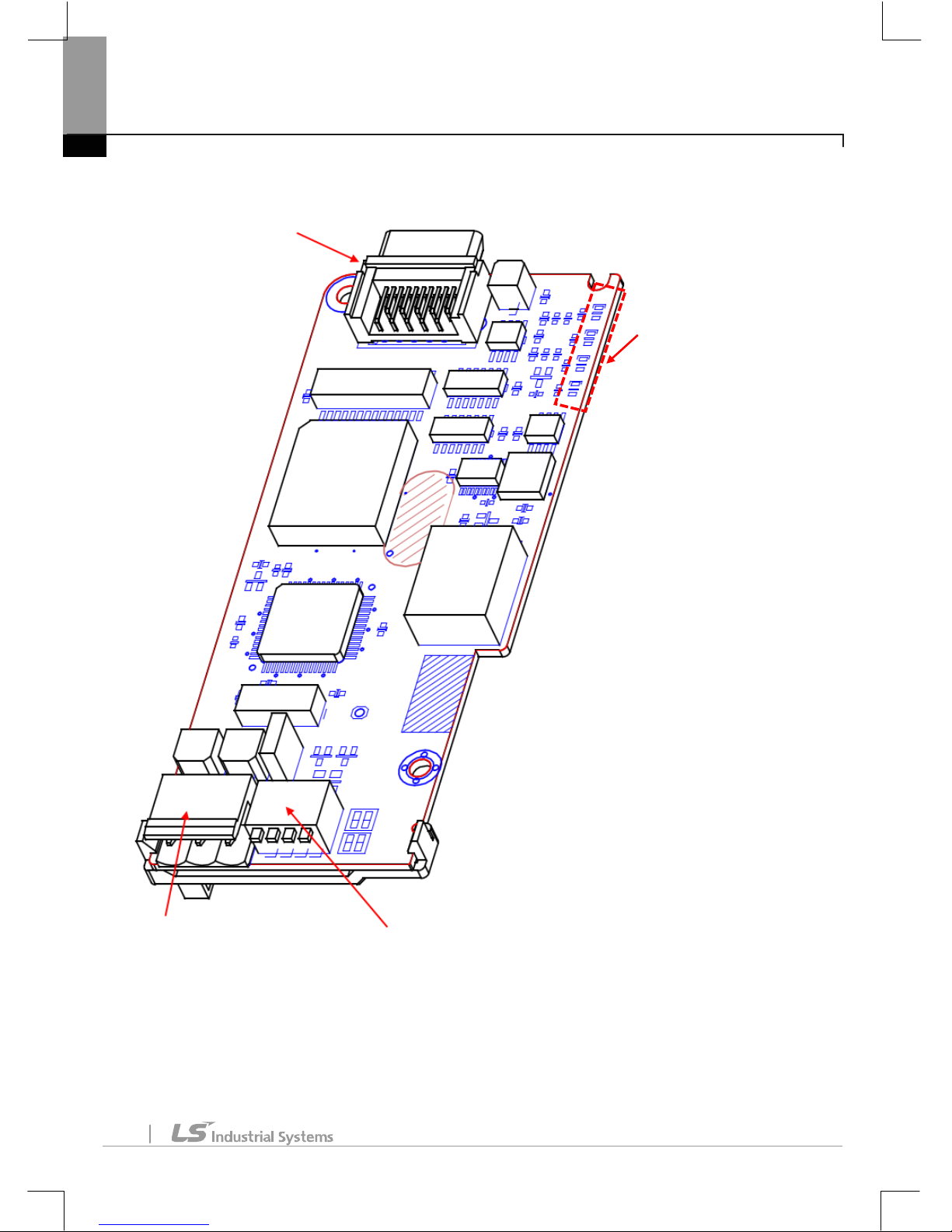
2.2 Device Layout
Connector to
the Inverter
Connector
(to Inverter)
DIP Switch
-Terminal resistance
-Service Pin Configuration
Communication
Connector (A, B, S)
LED
-CPU Operation
-Error
-Service
-COM

H100LonWorksManual
5
2.3 Installing the H100 LonWorks Communication Module
Warning
Turn off the power to the inverter before installation and network connection. Installing or removing the
communication module while the power is on may damage the inverter or the LonWorks communication module.
Make sure that the inverter is fully discharged before installing or removing the H100 LonWorks communication
Module.
■
Turn off the inverter and remove
the power terminal block cover.
■
Remove the keypad(2),
and then remove the top cover(3).
(1)
(2)
(3)

H100LonWorksManual
6
■
Install the H100 LonWorks communication
module (4) into the connector on the I/O board.
■
Secure the communication module with the 2 screws supplied with the device.
(4

H100LonWorksManual
7
■
Replace the top cover (5), then the keypad (6).
■
Replace the power terminal block cover (7). The inverter is now ready for use.
(7)
(5)
(6)

H100LonWorksManual
8
2.4 Wiring the H100 LonWorks Communication Module
The H100 Lon Works communication module has a connector socket for network connection.
The following table describes the details of the connector. Connector #1 and #2 are for the LonWorks
communication connection. The LonWorks communication connection does not require a certain order of polarity in
network wiring. Therefore, arranging of the polarity is not necessary.
No
Signal
Description
1
A
Network signal cable (no polarity)
2 B 3
S
Shield
Note
Use the 3-pin cable connector (PTR AK 950/03-5.0-GREEN) supplied with the device to connect the H100 LonWorks
communication module to a network.
2.5 Configuring a Network
Warning
Turn off the power to the inverter before installation and network connection. Installing or removing the
communication module while the power is on may damage the inverter and the LonWorks communication module.
Make sure that the inverter is fully discharged before installing or removing the H100 LonWorks communication
Module.
The LonWorks network allows for various types of network topology.
Appropriate network termination is required to guarantee data reliability and to reduce noise. The H100 LonWorks
communication module has built-in terminal resistance. Therefore, network termination can be made by simply
turning on the termination switch.
For a bus network, turn on the termination switch of the H100 LonWorks communication modules at both ends.

H100LonWorksManual
9
When the termination switch is set to BUS, 100Ω 1/8W termination resistance is connected between communication
terminals A and B.
For a free topology network connection, terminate one module on the network. When the termination switch is set to
FT, 50Ω 1/8W termination resistance is connected between communication terminals A and B.
The following table describes the type and feature of the termination resistance for each switch position.
<Termination Switch Configuration for the H100 LonWorks communication module>
Switch Position
Termination Type
FT
For use with a free topology network
50Ω terminal resistance
Terminate one module on the network.
NO
Termination is not used.
BUS
For use with a bus topology
100Ω terminal resistance
Terminate two modules at the ends of the network.
① NO
③ BUS
Bus Topology
(100 Ω)
② FT
Free Topology
(50 Ω)
ON
1 2 3 4
ON
1 2 3 4
ON
1
2 3 4

H100LonWorksManual
10
2.6 Installation Guidelines
Refer to the following guidelines when installing the H100 LonWorks communication module.
1. When you unpack the H100 LonWorks communication module, inspect the device to make sure that it is not
physically damaged.
2. Connect power to the H100 inverter and test the module to ensure that all functions work properly. Use the
keypad to operate the inverter and ensure that it operates normally.
3. Turn off the inverter and wait for at least five minutes for the internal charge to fully discharge. Before
working on the H100 inverter, test the DC link voltage to ensure that the charge is at a safe level.
4. Install the H100 LonWorks communication module in the H100 inverter. Remove the covers from the H100
inverter before installing the communication module.
5. Connect communication cables A and B to the H100 communication module. Polarity arrangement is not
necessary because the LonWorks communication module does not require specific network wiring polarity.
Make sure that the cables are connected securely.
6. If the node (the H100 inverter) is the last device on the network, terminate the network by setting the
termination switch.
7. To configure the LonWorks communication module, download the external interface file
(H100_LONWORKS.XIF) from the LSIS web site
(
http://www.lsis.com/support/download/
)
.
8. Turn on the power to the inverter and use the keypad to ensure that CNF-30 Option-1 Type displays
‘LonWorks.’
9. Configure the Lon Works communication parameters.
10. Inspect the H100 Lon Works communication module’s LED status. The ‘Service’ LED flashes in 2-sec intervals
if the device has not been configured.
11. Turn off the power to the H100 inverter and wait for 5 minutes until the DC link voltage discharges. Replace
the inverter covers. The installation process is finished. Turn the power on to the H100 inverter, and then
configure the device using the network tool.
Note
After first installing the H100 communication module, it must be configured at least once before it can communicate
with the inverter. Communication will be available once the communication module is configured after installation.
While configuring the communication module, an ‘Option Trip’ occurs because internal-interface communication
is not available immediately after installation. Bypass the ‘Option Trip’ at this stage and operate the inverter.
The communication module will communicate with the inverter properly once it is configured.
To configure the H100 communication module, turn the service switch ON, and then turn it off. The service LED will
turn off if the module was successfully configured.

H100LonWorksManual
11
2.7 Maximum Ranges for Different Network Cables
As shown in the following table, the maximum ranges of a network are limited based on the topology and the type of
cables used. Reliable network communication cannot be guaranteed beyond the maximum ranges listed in the table.
BUS Topology
Free Topology
Cable Type
Maximum Bus Length
Belden 85102
2,700 m
Belden 8471
2,700 m
Level IV, 22AWG
1,400 m
JY(St) Y 2x2x0.8
900 m
TIA Category 5
900 m
Cable Type
Maximum Distance between
Devices
Maximum
Total Range
Belden 85102
500 m
500 m
Belden 8471
400 m
500 m
Level IV, 22AWG
400 m
500 m
JY(St) Y 2x2x0.8
320 m
520 m
TIA Category 5
250 m
450 m

H100LonWorksManual
12
3. Inverter Parameters
3.1 Table of Parameters
Code
Parameter Name
Default Value
Settings
CNF-30
Option-1 Type
-
-
DRV-06
Cmd Source
1.Fx/Rx-1
0. Keypad
1. Fx/Rx-1
2. Fx/Rx-2
3. Int 485
4. FieldBus
5.Time Event
DRV-07
Freq Ref Src
0.Keypad-1
0. Keypad-1
1. Keypad-2
2. V1
4. V2
5. I2
6. Int 485
7. Fieldbus
9. Pulse
BAS-04
Cmd 2nd Src
1. Fx/Rx-1
0. Keypad
1. Fx/Rx-1
2. Fx/Rx-2
3. Int 485
4. FieldBus
5.Time Event
BAS-05
Freq 2nd Src
0. Keypad-1
0. Keypad-1
1. Keypad-2
2. V1
4. V2
5. I2
6. Int 485
7. Fieldbus
9. Pulse

H100LonWorksManual
13
Code
Parameter Name
Default Value
Settings
IN-65–71
P1–P7 Define
17. 2ndSource
COM-06
FBus S/W Ver
-
COM-09
FBus LED
-
COM-10
Opt Parameter1
-
-
COM-11
Opt Parameter2
COM-12
Opt Parameter3
COM-13
Opt Parameter4 - -
COM-14
Opt Parameter5
0
0 1 COM-31
Para Status-1
0x000A
0–0xFFFF
COM-32
Para Status-2
0x000E
0–0xFFFF
COM-33
Para Status-3
0x000F
0–0xFFFF
COM-34
Para Status-4
0x0000
0–0xFFFF
COM-35
Para Status-5
0x0000
0–0xFFFF
COM-36
Para Status-6
0x0000
0–0xFFFF
COM-37
Para Status-7
0x0000
0–0xFFFF
COM-38
Para Status-8
0x0000
0–0xFFFF
COM-51
Para Control-1
0x0005
0–0xFFFF
COM-52
Para Control-2
0x0006
0–0xFFFF
COM-53
Para Control-3
0x0000
0–0xFFFF
COM-54
Para Control-4
0x0000
0–0xFFFF
COM-55
Para Control-5
0x0000
0–0xFFFF
COM-56
Para Control-6
0x0000
0–0xFFFF
COM-57
Para Control-7
0x0000
0–0xFFFF
COM-58
Para Control-8
0x0000
0–0xFFFF
COM-94
CommUpdata
0.No
0. No
1. Yes
PRT-12
Lost Cmd Mode
0.None
0. None
1. Free-Run
2. Dec
3. Hold Input
4. Hold Output
5. Lost Preset
PRT-13
Lost Cmd Time
1.0 sec
0.1 – 120.0 sec
PRT-14
Lost Preset F
0 Hz
Start Frequency – Max frequency

H100LonWorksManual
14
3.2 Basic Field Bus Parameters
3.2.1 Communication Module Information– Option Type (CNF-30)
CNF-30
Option Type
This parameter automatically displays the name of the currently installed communication module.
If the LonWorks communication module is installed, CNF-30 Option Type displays ‘LonWorks.’
If the CNF-30 Option Type does not display any communication module names, this may mean that there is a faulty
connection between the inverter and the LonWorks communication module.
3.2.2 Command Source Options–Cmd Source (DRV-06)
DRV-06
Cmd Source
This parameter is used to select a command source.
To operate the inverter using the Lon Works communication, setDRV-06Cmd Source to ‘4.Fieldbus.’
3.2.3 Source of Frequency Reference Options– Freq Ref Src (DRV-07)
DRV-07
Freq Ref Src
This parameter is used to select a frequency reference.
To provide a frequency reference using the LonWorks communication, set DRV-07 Freq Ref Src to ‘7.Fieldbus.’
3.2.4 Secondary Command Source Options (for switching between two different command sources)
BAS-04
Cmd 2nd Src
BAS-05
Freq 2nd Src
IN-65–71
P1–P7 Define
This parameter is used to provide a second command source (frequency reference and run command) using the multipurpose input terminals. If the inverter is operated by remote network commands from network modules such as the
Lon Works communication module, this parameter may be used to stop remote operation and switch to local
operation using the inverter keypad.
This feature requires that the multi-purpose terminals P1–P7 (parameters IN65–71) are set to ‘2nd Source.’
3.2.5 Version information for the installed Communication Module– Fbus S/W Ver (COM-06)

H100LonWorksManual
15
This parameter is used to display the version information about the Lon Works communication module that is
installed in the inverter.
3.2.6 Communication Module LED Status Display– FbusLED (COM-9)
This parameter is used to display the status of the four LEDs (CPU, Error, Service, and COM) of the
communication module on the inverter keypad.
Each bit indication(On or Off) on the keypad display, from right to left, represent the status of the COM, Service,
Error and CPU LED.
An example of COM-09 LED State – 1101
LED
COM
(GREEN)
SERVICE
(GREEN)
ERR
(RED)
CPU
(GREEN)
Status
ON
ON
OFF
ON
Keypad Display
3.2.7 Display the Neuron ID– Opt Parameter1–3(COM-10–12)
COM-10
Opt Parameter1
COM-11
Opt Parameter2
COM-12
Opt Parameter3
These read-only parameters are used to display on the keypad the neuron IDs (a 6Byte data value) stored in the
neuron chip of the communication module. Parameters COM10–12 display the neuron ID information in HEX values,
in the order of upper to lower level information.
The information in the neuron IDs 1–3 may be used when you are installing the network manually without using the
service pin on the Lon Works communication module.

H100LonWorksManual
16
3.2.8 Display Node Status– Opt Parameter4(COM-13)
COM-13
Opt Parameter4
This read-only parameter is used to display the network interface status. When the interface is operating normally,
‘Configured on-line’ is displayed. This means that the relevant node has been commissioned by the network and is on-
line. ‘Soft’, ‘Bypass’, or ‘Hard off-line’ states indicate that the node failed to participate in the network.
Values
Description
0
Unknown state
1
Not configured
2
Application unassigned
3
Configured on-line
4
Configured off-line
5
Soft off-line
6
Configured bypass off-line
7
Hard off-line, Bypass off-line
3.2.9 Enable Service Pin– Opt Parameter5 (COM-14)
COM-14
Opt Parameter5
This parameter is used to enable the service pin feature without using the service pin switch on the LonWorks
communication module. Set COM-14 Service Pin Enable to ‘1’ to enable the service pin feature. This allows the Lon
Works communication module to send its Neuron ID and Program ID to the network.
Note
The Service Pin may be enabled on the keypad ONCE OLNY, after the inverter has been turned on the first time.
Once decommissioned from the configuration tool, the inverter cannot be commissioned again on a network using
the ‘Enable Service Pin’ parameter. You must turn on the service pin switch on the LonWorks communication module
to connect to the network.

H100LonWorksManual
17
3.2.10 User Object Output Variables (COM-31–38)
COM-31–38
Para Status-1–8
This parameter is used to configure the addresses for User Object output variables. For more details, refer to the ‘User
Object’ section of this manual.
3.2.11 User Object Input Variables (COM-51–58)
COM-51–58
Para Control-1–8
This parameter is used to configure the addresses for User Object input variables. For more details, refer to the ‘User
Object’ section of this manual.
3.2.12 Communication Update (COM-94)
After making changes to the parameters related to configuring Drive Objects using the keypad, a communication
update is required to apply the changes. Set COM 94 Comm Update to ‘Yes’ to perform a communication update.
After the update, the Comm Update parameter automatically changes back to ‘No.’
Keypad parameters that require the communication update are listed in the table below.
Codes
Parameters
DRV-03
Acc Time
DRV-04
Dec Time
DRV-18
Base Frequency
DRV-19
Start Frequency
DRV-20
Max Frequency
BAS-11
Pole Number
Note
After commissioning the H100 Lon Works communication module, COM-94 Comm Update must be set to ‘Yes’ to
apply the inverter’s configuration properties configured using the keypad.

H100LonWorksManual
18
3.2.13 Operation Options for a Lost Command– Lost Cmd Mode (PRT-12)
DRV-06
Cmd Source
DRV-07
Freq Ref Src
PRT-12
Lost Cmd Mode
PRT-13
Lost Cmd Time
PRT-14
Lost Preset F
This parameter is used to select an operation mode to be used when the command is lost. When remote command
via network is lost for the ‘lost command decision time’, the inverter decides that the command is lost.
This feature is available only when DRV-06 is set to ‘4.Fieldbus,’ or when DRV-07 is set to ‘7.Fieldbus.’
With this feature enabled, the selected operation mode is used when the network command is lost.
Settings
Description
0
None
Keeps the inverter operation at lost command.
1
Free-Run
The inverter blocks output. The motor performs a free-run stop.
2
Dec
The motor decelerates and then stops at the time set at PRT-07 Trip Dec
Time.
3
Hold Input
The inverter calculates the average input value for 10 sec before the loss of
the speed command and uses it as the speed reference.
4
Hold Output
The inverter calculates the average output value for 10 sec before the loss
of the speed command and uses it as the speed reference.
5
Lost Preset
The inverter operates at the frequency set at PRT-14 Lost Preset F.

H100LonWorksManual
19
3.2.14 Lost Command Decision Time– Lost Cmd Time (PRT-13)
DRV-06
Cmd Source
DRV-07
Freq Ref Src
PRT-12
Lost Cmd Mode
PRT-13
Lost Cmd Time
This parameter is used to set the time the inverter takes to decide that the command is lost. When the remote
command via network is lost for the lost command decision time (PRT-13 Lost Cmd Time + the time set at
nciRdvHrtBt), the inverter decides that the command is lost.
This feature is available only when DRV-06 is set to ‘4.Fieldbus,’ or when DRV-07 is set to ‘7.Fieldbus.’ If the network
command is recovered before the lost command decision time (PRT-13 Lost Cmd Time + the time set at nciRdvHrtBt)
is passed, the inverter does not output a fault trip and continues normal operation.
Caution
Lost command time protection operates only when the ‘nciRcvHrtBt’ variable is set to any value other than ‘0.’
Lost Command Period
Lost Command Period
Comm Line Status
Command was
recovered before
the Lost Cmd Time.
Lost command was
not detected.
Lost Command was detected.
The inverter runs according to
the Lost Cmd Mode Settings.
Time

H100LonWorksManual
20
4. Functional Profile
4.1 Node Object
Network Input Variables
Function
Variable Name
SNVT Type
Min
Max
Node Object Request
nviRequest
SNVT_obj_request
-
-
4.1.1 ‘nviRequest’ Variable
The ‘nviRequest’input variable enables or updates the command inputs from a network. This input variable supports
RQ_ENABLE, RQ_DISABLE, RQ_CLEAR_ALARM, RQ_NORMAL, RQ_CLEAR_STATUS, RQ_UPDATE_STATUS,
RQ_REPORT_MASK.
Network Output Variables
Function
Variable Name
SNVT Type
Min
Max
Node Object Status
nvoStatus
SNVT_obj_status
-
-
4.1.2 ‘nvoStatus’ Variable
The following table shows the Node Object states indicated by the ‘nvoStatus’ output variable.
Bit Setting Description
Invalid ID
Invalid node ID has been requested.
Report mask
Reporting supported fields.
Disabled
RQ_DISABLE is active.
Electrical_fault
Drive fault has occurred.
Manual_control
Drive is in local control mode.
In_alarm
Drive alarm has been turned on.
Node Object
Mandatory
Network
Variables
nviRequest
SNVT_obj_request
nv1
nvoStatus
SNVT_obj_state
nv2
Input Network
Variable
Output Network
Variable

H100LonWorksManual
21
4.2 Drive Object
Mandatory
Network
Variables
nviDrvSpeedStpt
SNVT_switch
nv1
nvoDrvSpeed
SNVT_lev_percent
nv4
Variable Speed Motor
Drive (6010)
Optional
Network
Variables
nviDrvSpeedScale
SNVT_lev_percent
nv2
nvoDrvCurrent
SNVT_amp
nv3
nvoDrvVolt
SNVT_volt
nv5
nvoDrvPwr
SNVT_power_kilo
nv6
nvoDrvRunHours
SNVT_time_hour
nv7
nc17 nciLocation (Optional)
nc50 nciMaxSpeed (Mandatory)
nc53 nciMinSpeed (Mandatory)
nc48 nciRcvHrtBt (Optional)
nc49 nciSndHrtBt (Mandatory)
nc52 nciMinOutTm (Optional)
nc158 nciNmlSpeed (Mandatory)
nc159 nciNmlFreq (Mandatory)
nc160 nciRampUpTm (Mandatory)
nc161 nciRampDownTm (Mandatory)
nc162 nciDrvSpeedScale (Optional)
Configuration Properties
Input Network
Variable
Output Network
Variable

H100LonWorksManual
22
Network Input Variables
Function
Variable Name
SNVT Type
Min
Max
Drive Speed Setpoint
nviDrvSpeedStpt
SNVT_switch
N/A
N/A
Drive Speed SetpointScaling
nviDrvSpeedScale
SNVT_lev_percent
-163.840%
163.830%
4.2.1 ‘nviDrvSpeedStpt’ and ‘nviDrvSpeedScale’ Variables
Definition
Network input SNVT_switch nviDrivSpeedStpt
Network input SNVT_lev_percent nviDrvSpeedScale
Description
Variables ‘nviDrvSpeedStpt’ and ‘nviDrvSpeedScale’ are used for run commands and speed references. The state
variable value for ‘nviDrvSpeedStpt’ decides whether to run or stop an inverter. The inverter stops when the
‘nviDrvSpeedStpt’ state is set to ‘0’, and runs when it is set to ‘1.’
The ‘nviDrvSpeedScale’ variable provides rotation direction information for the inverter. The inverter operates in the
forward direction (Fx) when the ‘nviDrvSpeedScale’ value is set to a positive number, and in the reverse direction (Rx)
when it is set to a negative number.
Frequency reference information is given by a combination of the ‘nviDrvSpeedScale’ and ‘nviDrvSpeedStpt’ variable
values. The ‘nviDrvSpeedScale’ and ‘nviDrvSpeedStpt’ values are in percentages (%).
To calculate the frequency reference, multiply the ‘nviDrvSpeedStpt’ value with the ‘nviDrvSpeedScale’ value, and
then multiply the resulting value (%) with the base frequency. This means that the ‘nviDrvSpeedScale’ variable
provides the scale value for the ‘nviDrvSpeedStpt’ variable.
For Example, if the ’nviDrvSpeedStpt’ value is set to ‘100 (%)’ and the ‘nviDrvSpeedScale’ value is set to ‘-80 (%),’ the
resulting value will be -80% (1 X -0.8 = -0.8). As a result, the inverter operates in the reverse direction, at a frequency
that is 80% of the base frequency (if the base frequency is set to 60.00 Hz) and the resulting frequency reference will
be 48Hz (60.00Hz X 0.8).
The ‘nviDrvSpeedScale’ value range is between -163.840% – 163.830%. Therefore, a value of 0x7fff (+163.835%)
becomes an invalid data.

H100LonWorksManual
23
NviDrvSpeedStpt States and Value Range
State
Value
Inverter Operating Frequency / Operation State
0
-
Stop
1
0
Frequency reference at 0% of the base frequency
1
0.5–100.0
Frequency reference at 0.5–100.0% of the base frequency
1
100.0
Frequency reference at 100% of the base frequency
0xFF
-
Auto
In the communication (COMM) group, set DRV-06 Cmd Source to ‘FieldBus’ and DRV-07 Freq Ref Src to ‘FieldBus’
using the keypad. These settings configure the inverter to receive run commands and frequency references from the
LonWorks communication.
Code Number/
Common Area Address
Code Description
Default
Settings
DRV-06
Cmd Source
Fx/Rx-1
Keypad
Fx/Rx-1
Fx/Rx-2
Int 485
FieldBus
Time Event
DRV-07
Freq Ref Src
Keypad-1
Keypad-1
Keypad-2
V1
Reserved
V2
I2
Int 485
FieldBus
Reserved
Pulse
nviDrvSpeedScale Range
-163.840% – 163.830%
nviDrvSpeedScale Default
0.000%

H100LonWorksManual
24
Inverter Parameters Related to the ‘nviDrvSpeedStpt’ and ‘nviDrvSpeedScale’ Variables
Code Number/
Common Area Address
Code Description
Default
Range
0x0005
Frequency Command
0.00 Hz
0.00 – 400.00
0x0006
Run Command
Refer to the ‘Common Area’ section.
DRV-18
Base Frequency
60.00 Hz
30.00–400.00
Note
Network variables ‘nviDrivSpeedStpt’ and ‘nviDrvSpeedScale’ may be used in combination with the ‘nciRcvHrtBt’
variable to configure the lost command options.
Network Output Variables
Function
Variable Name
SNVT Type
Min
Max
Drive Speed Feedback
nvoDrvSpeed
SNVT_lev_percent
-163.840%
163.830%
Actual Motor Current
nvoDrvCurnt
SNVT_amp
0.0 A
3276.7 A
Drive Output Voltage
nvoDrvVolt
SNVT_volt
0.0 V
3276.7 V
Actual Drive Power
nvoDrvPwr
SNVT_power_kilo
0.0 kW
6553.5 kW
Drive total running hours
nvoDrvRunHours
SNVT_time_hour
0 h
65535 hr
‘nvoDrvSpeed’ Variable
Definition
Network output SNVT_lev_percent nvoDrvSpeed
Description
The ‘nvoDrvSpeed’ variable is used to output the inverter’s operating frequency as a percentage of the base
frequency. The ‘nvoDrvSpeed’ value is positive if the inverter is running in the forward direction (Fx) and negative if it
is running in the reverse direction (Rx).
For example, if the base frequency is set at 60.00 Hz, and the inverter is running at 30.00 Hz in the reverse direction
(Rx), ‘nvoDrvSpeed’ outputs a value of-50.000%.
Typical Range
-163.840 – 163.830 % (0.001 %)

H100LonWorksManual
25
Inverter Parameters Related to the ‘nvoDrvSpeed’ Variable
Code Number/
Common Area Address
Code Description
Default
Range
0x000A
Output Frequency
0x000E
Status of Inverter(FWD, REV)
DRV-18
Base Frequency
60.00 Hz
30.00–400.00
4.2.4 ‘nvoDrvCurnt’ Variable
Definition
Network output SNVT_amp nvoDrvCurnt
Description
The ‘nvoDrvCurnt’ variable is used to output the inverter’s output current in amperes (A).
Typical Range
0.0 – 3276.6 A (0.1 A)
Inverter Parameters Related to the ‘nvoDrvCurnt’ Variable
Code Number/
Common Area Address
Code Description
x0009
Current
4.2.5 ‘nvoDrvVolt’ Variable
Definition
Network output SNVT_volt nvoDrvVolt
Description
The ‘nvoDrvVolt’ variable is used to output the inverter’s output voltage (V).
Typical Range
0.0 – 700.0 V (0.1 V)

H100LonWorksManual
26
Inverter Parameters Related to the ‘nvoDrvVoltCurnt’ Variable
Code Number/
Common Area Address
Code Description
0x000B
Output Voltage
4.2.6’nvoDrvPwr’ Variable
Definition
Network output SNVT_power_kilo nvoDrvPwr
Description
The ‘nvoDrvPwrNetWork’ variable is used to output the inverter’s power output in kilowatts (kW).
Typical Range
0.0 – 6553.4 kW (0.1 kW)
Inverter Parameters Related to the ‘nvoDrvPwr’Variable
Code Number/
Common Area Address
Code Description
MAK-01
0x0301
Inverter Capacity
4.2.7’nvoDrvRunHours’ Variable
Definition
Network output SNVT_time_hour nvoDrvRunHours
Description
The ‘nvoDrvRunHours’ variable is used to output the inverter’s total operation time.
Inverter Parameters Related to the ‘nvoDrvPwr’ Variable
Code Number/
Common Area Address
Code Description
0x0342
0x0343
Total Operation Time
0x0342 – in days
0x0343 – in minutes
Network Configuration Variables

H100LonWorksManual
27
Function
Variable Name
Optional/
Mandatory
SNVT Type
Location Label
nciLocation
Optional
SCPTlocation
Maximum Motor Speed
nciMaxSpeed
Mandatory
SCPTmaxSetpoint
Minimum Motor Speed
nciMinSpeed
Mandatory
SCPTminSetpoint
Receive Heartbeat Time
nciRcvHrtBt
Optional
SCPTmaxRcvTime
Send Heartbeat Time
nciSndHrtBt
Mandatory
SCPTmaxSndTime
Minimum Send Time
nciMinOutTm
Optional
SCPTMinOutTime
Nominal Motor Speed in RPM
nciNmlSpeed
Mandatory
SCPTnomRPM
Nominal Motor Frequency
nciNmlFreq
Mandatory
SCPTnomFreq
Minimum Ramp Up Time
nciRampUpTm
Mandatory
SCPTrampUPTm
Minimum Ramp Down Time
nciRampDownTm
Mandatory
SCPTrampDownTm
Default Value for nviDrvSpeedScale
nciDrvSpeedScale
Optional
SCPTdefScale
Note
After modifying the parameters related to configuration variables from the keypad, set COM-94Comm Update to
‘Yes’ to apply the changes to the configuration variables.
Code Number/
Common Area Address
Code Description
Default
Options
COM-94
Comm Update
No
No
Yes

H100LonWorksManual
28
4.2.8 Location Label (Optional)
Definition
Network config input SNVT_str_asc nciLocation
Description
The ‘nciLocation’ variable is used to obtain the physical location information (6 byte location string) from the neuron
chip.
Default
Empty spaces
4.2.9 Maximum Motor Speed (Mandatory)
Definition
Network config input SNVT_lev_percent nciMaxSpeed
Description
The ‘nciMaxSpeed’ variable is used to configure the maximum speed of a motor. The ‘nciMaxSpeed’ value is
expressed as a percentage of the nominal frequency (nciNmlFreq) configuration value.
For example, if the ‘nciNmlFreq’ is 60.0 Hz and the ‘nciMaxSpeed’ is set to 120%, the resulting frequency is 72 Hz (60.0
x 1.2). The maximum frequency configured by these variables can be viewed on the keypad at DRV-20 Max Freq.
Changes cannot be made to the ‘nciMaxSpeed’ variable while the inverter is running. Stop the inverter operation
before making changes to the ‘nciMaxSpeed’ variable.
The default value for the ‘nciMaxSpeed’ variable is 100.00%, which is 100% of the base frequency (DRV-18Base Freq),
and the resulting value becomes the maximum frequency (DRV-20 Max Freq).
The ‘nciMaxSpeed’ variable values must comply with the following formula.
Typical Range
100.000 – 150.000 % (0.001% increments)
Default
100.000%
Note
As shown in the descriptions above, the ‘nciMinFreq(nciMinSpeed)’ and the ’nciMaxSpeed(%)’ values adjust the
maximum frequency set at DRV-20 Max Freq. Because the maximum frequency (Max Freq) must fall within the 40–
120.00 Hz range, the inverter will maintain the current maximum frequency if the ‘nciNmlFreq’ is changed to a value
less than 40 Hz. (For example, if the ‘nciNmlFreq’is set to 30 Hz and the ‘nciMaxSpeed‘ is set to 100.00%, the
maximum frequency will not be changed to 30 Hz).
840.163840.163 SpeedMaximumSpeedMinimum

H100LonWorksManual
29
Inverter Parameters Related to the ‘nciMaxSpeed’ VariableI
Code Number/
Common Area Address
Code Description
Default
Range
DRV-18
Base Frequency
60.00 Hz
30.00 – 400.00
DRV-20
Max Frequency
60.00 Hz
40.00 – 400.00
4.2.10 Minimum Motor Speed (Mandatory)
Definition
Network config input SNVT_lev_percent nciMinSpeed
Description
The ‘nciMinSpeed’ variable is used to configure the minimum speed of a motor. The ‘nciMinSpeed’ value is expressed
as a percentage of the nominal frequency (nciNmlFreq) configuration value. For example, if the ‘nciNmlFreq’ is 60.0
Hz and the ‘nciMinSpeed’ is set to 10%, the resulting frequency is 6 HZ (60.0 x 0.1). The minimum frequency
configured by these variables can be viewed on the keypad (DRV-19 Start Freq).
Changes cannot be made to the ‘nciMinSpeed’ variable while the inverter is running. Stop the inverter before making
any changes to the ‘nciMinSpeed’ variable.
The default value for the ‘nciMinSpeed’ variable (expressed as percentage) is calculated based on the base frequency
and the start frequency (‘DRV-19 Start Freq’ divided by ‘DRV-18 Base Freq’). Because the default for the start
frequency (DRV-19 Start Freq) is 0.5 Hz, the ‘nciMinSpeed’ variable value becomes 0.8% (0.5/60=0.0083, rounded off
and expressed as a percentage).
The ‘nciMinSpeed’ variable values must comply with the following formula.
Typical Range
0.000– 40.000 % (0.001 % increments)
Default
0.000%
※
As shown in the descriptions above, the ‘nciMinFreq(nciMinSpeed)’ and the’nciMaxSpeed (%)’ values adjust the
maximum frequency set at DRV-20 Max Freq. Because the maximum frequency (Max Freq) must fall within the 40–
400 Hz range, the inverter will maintain the current maximum frequency if the ‘nciNmlFreq’ is changed to a value less
than 40 Hz. (For example, if the ‘nciNmlFreq’ is set to 30 Hz and the ‘nciMaxSpeed‘ is set to 100.00%, the maximum
frequency will not be changed to 30 Hz).
830.163840.163 SpeedMaximumSpeedMinimum

H100LonWorksManual
30
Inverter Parameters Related to the ‘nciMaxSpeed’ Variable
Code Number/
Common Area Address
Code Description
Default
Range
DRV-18
Base Frequency
60.00 Hz
30.00 – 400.00
DRV-20
Start Frequency
0.50 Hz
0.01–10.00
4.2.11 Receive Heart Beat Time (Optional)
Definition
Network config input SNVT_time_sec nciRcvHrtBt
Description
The ‘nciRcvHrtBt’ variable is used to configure the maximum update interval for the network input variables
‘nviDrvSpeedStpt’ and ‘nviDrvSpdScale’. If the ‘nviDrvSpeedStpt’ and ‘nviDrvSpdScale’ variables are not updated for
the set time (‘nciRcvHrBt’ time value + PRT-13 Lost Cmd Time), the inverter decides that the command is lost. It then
runs in the operation mode set by thePRT-12 Lost Cmd Mode.
Lost command time protection operates only when the ‘nciRcvHrtBt’ variable is set to a value other than 0.0 sec,
DRV-06 Cmd Source or DRV-07 Freq Ref Src is set to ‘Fieldbus’, and PRT-12 Lost Cmd Mode is set to any other value
than ‘None’.
The lost command protection feature is disabled if the ‘nciRcvHrBt’ variable is set to 0.0 sec.
Typical Range
0.0 – 120.0 sec (0.1 sec increments)
A value of 0xFFFF(6553.5 sec) is invalid data.
Default
0.0 sec (Receive Heart Beat feature is disabled)

H100LonWorksManual
31
Inverter Parameters Related to the ‘nciRcvHrtBt’ Variable
Code Number/
Common Area Address
Code Description
Default
Settings
DRV-06
Cmd Source
Fx/Rx-1
Keypad
Fx/Rx-1
Fx/Rx-2
Int 485
FieldBus
Time Event
DRV-07
Freq Ref Src
Keypad-1
Keypad-1
Keypad-2
V1
Reserved
V2
I2
Int 485
FieldBus
Reserved
Pulse
PRT-12
Lost Cmd Mode
None
None
FreeRun
Dec
Hold Input
Hold Output
Lost Preset
PRT-13
Lost Cmd Time
1.0sec
0.1–120.0sec
Caution
When the LonWorks network is used as a command source, the inverter’s lost command time becomes the time set
at ‘nciRcvHrtBt’ and PRT-13Lost Cmd Time added together. However, if the ‘nciRcvHrBt’ variable is set to 0.0 sec, the
lost command protection feature is disabled.

H100LonWorksManual
32
4.2.12 Send Heart Beat Time (Mandatory)
Definition
Network config input SNVT_time_sec nciSndHrtBt
Description
The ‘nciSndHrtBt’ variable is used to configure the time it takes to perform a data update on the network, regardless
of the presence of changes in the data.
The ‘nciSndHrtBt’ variable configures the maximum output time for the network output variables ‘nvoDrvSpeed’,
‘nvoDrvCurnt’, ‘nvoDrvVolt’, ‘nvoDrvPwr’, and ‘nvoDrvRunHours.’
Typical Range
0.0 – 6553.4 sec
A value of 0xFFFF (6553.5 sec) is invalid data.
Default
0.0 sec (Send Heart Beat feature is disabled)
4.2.13 Minimum Out Time (Optional)
Definition
Network config input SNVT_time_sec nciMinOUtTm
Description
The ‘nciMinOUtTm’ variable is used to configure the minimum wait time before the output variables ‘nvoDrvSpeed’,
‘nvoDrvCurnt’, ‘nvoDrvVolt’, ‘nvoDrvPwr’, and ‘nvoDrvRunHours’ are sent to the network.
Rather than reflecting the changes in the variables each time they are made, a network update is performed when the
set period of ‘nciMinOutTm’ has elapsed to reflect the changes. This feature is used to decrease network traffic.
Typical Range
0.0 – 6553.4 sec (0.1 sec increments)
A value of 0xFFFF (6553.5 sec) is invalid data.
Default
0.0 sec (Minimum Out Time feature is disabled)
4.2.14 Nominal Motor Speed in RPM (Mandatory)
Definition
Network config input SNVT_freq_hz nciNmlSpeed
Description
The ‘nciNmlSpeed’ variable is used to configure the inverter’s base frequency.
The default value for the ‘nciNmlSpeed’ variable is 1800.00 RPM which is the default base frequency of 60Hz set at
DRV-18 Base Freq, expressed in PRM (for a 4-pole motor). When the ‘nciNmlSpeed’ value is changed, the value (RPM)

H100LonWorksManual
33
converted back to Hertz (Hz) is reflected in DRV-18 Base Freq.
The following formula converts an RPM value into Hertz (Hz). In this formula, the number of motor poles is set at M210 Pole Num. The motor pole number must be configured correctly to ensure proper operation.
Valid Range
0 – 65534 RPM (1 RPM)
Default
1800 RPM
Inverter Parameters Related to the ‘nciNmlSpeed’ Variable
Code Number/
Common Area Address
Code Description
Default
Range
BAS-11
0X0E0A
Pole Number
4
2–48
DRV-18
Base Frequency
60.00 Hz
30.00 – 400.00
Note
When a change is made to the ‘nciNmlSpeed’ variable, it is automatically reflected in the ‘nciNmlFreq’ value. For
example, if the current ‘nciNmlSpeed’ value is set to 1800 RPM, the ‘nciNmlFreq’ is set to 60.0 Hz, DRV-18 Base
Frequency is set to 60 Hz, and BAS-11 Pole Number is set to 4 (poles), decreasing the ‘nciNmlFreq’ value to 1700 RPM
changes the ’nciNmlFreq’ value to 56.7 Hz (a rounded-up value of the DRV-18 Base Frequency value), and DRV-18
Base Frequency to 56.66 Hz.
When the values set at ‘nciNmlSpeed’ or ‘nciNmlFreq’ are changed, the changes are reflected in DRV-19 Start
Frequency and Drv-20 Max Frequency as well. In the example above, if the ‘nciMaxSpeed’ is set to 100.000% and
‘nciMinSpeed’ is set to 10.000%, DRV-19 Start Frequency is changed to 5.66 Hz and Drv-20 Max Frequency is changed
to 56.66 Hz.
4.2.15 Nominal Motor Frequency (Mandatory)
Definition
Network config input SNVT_freq_hz nciNmlFreq
Description
The ‘nciNmlFreq’ is used to configure the motor’s base frequency. The ‘nciNmlFreq’ value is essential in configuring
the motor’s minimum and maximum frequency (‘nciMinSpeed’ and ’nciMaxSpeed’) because these values are
expressed as a percentage of the value set at ’nciNmlFreq.’ The default ‘nciNmlFreq’ value is 60 Hz which is the
default frequency set at DRV-18 Base Freq.
ploesmotor ofnumber the
120 Hz)Frequency( Base
minuteper rotation ofnumber The
poles

H100LonWorksManual
34
Valid Range
30.0–400.0 (0.1 Hz)
Default
60.0 Hz
Inverter Parameters Related to the ‘nciNmlFreq’ Variable
Code Number/
Common Area Address
Code Description
Default
Range
DRV-18
Base Frequency
60.00 Hz
30.00 – 400.00
4.2.16 Minimum Ramp Up Time (Mandatory)
Definition
Network config input SNVT_time_sec nciRampUpTm
Description
The ‘nciRampUpTm’ variable is used to configure the inverter’s acceleration time. When the ‘nciRampUpTm’ value is
changed, it is reflected in DRV-03 Acc Time. The default ‘nciRampUpTm’ value is 20.0 sec, which is the default
acceleration time that is set as DRV-03 Acc Time.
Valid Range
0.0–600.0 sec (0.1 sec increments)
Default
20.0 sec
Inverter Parameters Related to the ‘nciRampUpTm’ Variable
Code Number/
Common Area Address
Code Description
Default
Range
0x0007
DRV-03
Acc Time (Acceleration time)
20.0 sec
0.0 – 600.0
4.2.17 Minimum Ramp Down Time (Mandatory)
Definition
Network config input SNVT_time_secnciRampDownTm
Description
The ‘nciRampDownTm’ variable is used to configure the inverter’s deceleration time. When the ‘nciRampDownTm’
value is changed, it is reflected in DRV-04 Dec Time. The default ‘nciRampDownTm’ value is 30.0 sec, which is the
default acceleration time set at DRV-04 Dec Time.
Valid Range
0.0–600.0 sec (0.1 sec increments)
Default
30.0 sec

H100LonWorksManual
35
Inverter Parameters Related to the ‘nciRampDownTm’ Variable
Code Number/
Common Area Address
Code Description
Default
Range
0x0008
DRV-04
Dec Time (Deceleration time)
30.0 sec
0.0 – 600.0
4.2.18 Default for nviDrvSpeedScale (Optional)
Definition
Network config input SNVT_lev_percentnciDrvSpeedScale
Description
The ‘nciDrvSpeedScale’ value is used as the default value of the network output variable ‘nviDrvSpeedScale.’
Valid Range
-163.840– 163.830 (0.005 %)
Default
0.000 %
Note
The inverter parameters DRV-18 Base Freq, DRV-19 Start Freq, DRV-20 Max Freq, BAS-11 Pole Num, DRV-03 Acc
Time, and DRV-04 Dec Time are closely related to the configuration property variables ‘nciNmlFreq’, ‘nciNmlSpeed’,
‘nciMaxSpeed’, ‘nciMinSpeed’, ‘nciRampUPTm’, and ‘nciRampDownTm’ in Drive Objects.
After making changes to the parameter values for DRV-18 Base Freq, DRV-19 Start Freq, DRV-20 Max Freq, BAS-11
Pole Num, DRV-03 Acc Time, and DRV-04 Dec Time using the inverter keypad, either turn off the inverter and then
turn it back on, or set COM-94CommUpDate to ‘Yes’ to reflect the changes in the configuration property variables
‘nciNmlFreq’, ‘nciNmlSpeed’, ‘nciMaxSpeed’, ‘nciMinSpeed’, ‘nciRampUPTm’, and ‘nciRampDownTm’.
For example, if the inverter parameters are set as shown in the following table, the ‘nciMaxSpeed’ value becomes
120.000%, the ‘nciMinSpeed’ value becomes 20.000%, the ‘nciNmlSpeed’ value becomes 1,500 RPM, the ‘nciNmlFreq’
value becomes 50.0Hz, the ‘nciRampUpTm’ value becomes 19.0 sec, and the ‘nciRampDownTm’ becomes 29.0 sec.
Code
Parameter Name
Value
Code
Parameter Name
Value
DRV-03
AccTIme
19.0 sec
DRV-04
Dec TIme
29.0 sec
BAS-11
Pole Num
4
DRV-18
Base Freq
49.99 Hz
BAS-19
Start Freq
10.00 Hz
BAS-20
Max Freq
60.00 Hz
① The ‘nciNmlFreq’ variable value uses one decimal place and the DRV-18 Base Freq variable uses two decimal places.
Because of the difference, the DRV-18 Base Freq value needs to be rounded up to one decimal place before it is
adopted as the ‘nciNmlFreq’ variable. The value set at DRV-18 becomes 50 Hz after it is rounded up to one decimal

H100LonWorksManual
36
place, and the ‘nciNmlFreq’ value is 50 Hz.
The ‘nciNmlFreq’ values must be used in the formula for the base frequency values.
The maximum frequency (MaxFreq) value cannot be set higher than 163.830% of the base frequency (Base Freq).
Therefore, the maximum value of the ‘nciMaxSpeed’ variable is 163.830%.
49.99
1,500RPM
60.0
50.0
10.0
50.0
120.000%
20.00%

H100LonWorksManual
37
4.2 User Object (User Function Profile Type)
Mandatory
Network
Variables
User Object(20001)
nvoUsrParaState1
SNVT_count
nv9
nvoUsrParaState2
SNVT_count
nv10
nvoUsrParaState3
SNVT_count
nv11
nvoUsrParaState4
SNVT_count
nv12
nvoUsrParaState5
SNVT_count
nv13
nvoUsrParaState6
SNVT_count
nv14
nvoUsrParaState7
SNVT_count
nv15
nvoUsrParaState8
SNVT_count
nv16
nviUsrParaCtrl1
SNVT_count
nv1
nviUsrParaCtrl2
SNVT_count
nv2
nviUsrParaCtrl3
SNVT_count
nv3
nviUsrParaCtrl4
SNVT_count
nv4
nviUsrParaCtrl5
SNVT_count
nv5
nviUsrParaCtrl6
SNVT_count
nv6
nviUsrParaCtrl7
SNVT_count
nv7
nviUsrParaCtrl8
SNVT_count
nv8
Input Network
Variable
Output Network
Variable
nc1 nciUsrRcvHrtBt (Optional)
nc2 nciUsrSndHrtBt (Optional)
nc3 nciUsrMinOutTm (Optional)
Configuration Properties

H100LonWorksManual
38
Network Input Variables
Function
Variable Name
SNVT Type
Min.
Max.
User Parameter Control1
nviUsrParaCtrl1
SNVT_count
0
65535
User Parameter Control2
nviUsrParaCtrl2
SNVT_count
0
65535
User Parameter Control3
nviUsrParaCtrl3
SNVT_count
0
65535
User Parameter Control4
nviUsrParaCtrl4
SNVT_count
0
65535
User Parameter Control5
nviUsrParaCtrl5
SNVT_count
0
65535
User Parameter Control6
nviUsrParaCtrl6
SNVT_count
0
65535
User Parameter Control7
nviUsrParaCtrl7
SNVT_count
0
65535
User Parameter Control8
nviUsrParaCtrl8
SNVT_count
0
65535
4.3.1 nviUsrParaCtrl1–nviUsrParaCtrl8
Definition
Network input SNVT_count nviUsrParaCtrl1 –nviUsrParaCtrl8
Description
Network input variables ‘nviUsrParaCtrl1–nviUsrParaCtrl8’ are used to provide added flexibility while using LS
inverters. Because these variables are user-definable to match with the inverter parameters that the users intend to
adjust rather than permanently assigned to certain parameters, more convenient and enhanced configuration of the
inverter over a network becomes available.
For example, if the user decides to modify COM51–COM58 parameters over the network, these parameters may be
assigned to the network variables ‘nviUsrParaCtrl1–nviUsrParaCtrl8.’ Then, by registering addresses 0x0005
(Frequency Reference), 0x0006 (Command Source) and 0x0007 (Acceleration Time) to the inverter’s communication
parameters (COM51, COM52, and COM53), users can control the frequency reference with ‘nviUsrParaCtrl1’, provide
run commands with ‘nviUsrParaCtrl2,’ and adjust acceleration time with ‘nviUsrParaCtrl3.’
If the user intends to operate the inverter in the reverse (Rx) direction at 6000 Hz, with a 10.0 sec acceleration time,
‘nviUsrParaCtrl1’ may be set to 6000, ‘nviUsrParaCtrl2’ to 0x0004, and ‘nviUsrParaCtrl3’ to 100.

H100LonWorksManual
39
Inverter Parameters Related to the ‘nviUsrParaCtrl1– nviUsrParaCtrl8’ Variables
Code Number/
Common Area Address
Code Description
Default
Range
COM-50
User Parameter Control Number
3
0–8
COM-51
User Parameter Control 1
0x0005
0–0xFFFF
COM-52
User Parameter Control 2
0x0006
0–0xFFFF
COM-53
User Parameter Control 3
0x0000
0–0xFFFF
COM-54
User Parameter Control 4
0x0000
0–0xFFFF
COM-55
User Parameter Control 5
0x0000
0–0xFFFF
COM-56
User Parameter Control 6
0x0000
0–0xFFFF
COM-57
User Parameter Control 7
0x0000
0–0xFFFF
COM-58
User Parameter Control 8
0x0000
0–0xFFFF
Note
When the inverter is used on a Lon Works network, COM-50 User Parameter Control Number is automatically set to
‘8’. If the user sets COM-50 to any other value from the keypad, it automatically reverts back to ‘8.’
Network Output Variables
Function
Variable Name
SNVT Type
Min
Max
User Parameter State1
nvoUsrParaState1
SNVT_count
0
65535
User Parameter State2
nvoUsrParaState2
SNVT_count
0
65535
User Parameter State3
nvoUsrParaState3
SNVT_count
0
65535
User Parameter State4
nvoUsrParaState4
SNVT_count
0
65535
User Parameter State5
nvoUsrParaState5
SNVT_count
0
65535
User Parameter State6
nvoUsrParaState6
SNVT_count
0
65535
User Parameter State7
nvoUsrParaState7
SNVT_count
0
65535
User Parameter State8
nvoUsrParaState8
SNVT_count
0
65535

H100LonWorksManual
40
4.3.2 nviUsrParaState1–nviUsrParaState8
Definition
Network output SNVT_count NvoUsrParaState1–nvoUsrParaState8
Description
Network input variables ‘nvoUsrParaState1 – nvoUsrParaState8’ are used to provide flexibility in the monitoring
features of the LS inverters. Because these variables are user-definable to match with the inverter parameters that
the users intend to monitor, rather than permanently assigned to certain monitoring parameters, easy monitoring of
the inverter parameters over a network becomes available.
For example, if the user decides to monitor COM31–COM38 parameters over the network, these parameters may be
assigned to the network variables ‘nvoUsrParaState1 – nvoUsrParaState8.’ Then, by registering addresses
0x000A(Output Frequency), 0x000B(Output Voltage), and 0x941E (Jog Frequency) to the inverter’s communication
parameters (COM31, COM32, and COM33), users can monitor the output frequency with ‘nvoUsrParaState1’, the
output voltage with ‘nvoUsrParaState2,’ and the jog frequency with ‘nvoUsrParaState3.’
If the inverter is operating at 30 Hz with the DC link voltage of 150.0V and the jog frequency is 20.00 Hz,
‘nvoUsrParaState1’ displays 3000, ‘nvoUsrParaState2’ displays 1500, and ‘nvoUsrParaState3’ displays 2000.
Inverter Parameters Related to the ‘nviUsrParaState0– nviUsrParaState7’ Variables
Code Number/
Common Area Address
Code Description
Default
Range
COM-30
User Parameter State Number
3
0–8
COM-31
User Parameter State 1
0x000A
0–0xFFFF
COM-32
User Parameter State 2
0x000E
0–0xFFFF
COM-33
User Parameter State 3
0x000F
0–0xFFFF
COM-34
User Parameter State 4
0x0000
0–0xFFFF
COM-35
User Parameter State 5
0x0000
0–0xFFFF
COM-36
User Parameter State 6
0x0000
0–0xFFFF
COM-37
User Parameter State 7
0x0000
0–0xFFFF
COM-38
User Parameter State 8
0x0000
0–0xFFFF
Note
When the inverter is used on a LonWorks network, COM-30 User Parameter Control Number is automatically set to
‘8’. If the user sets COM-30 to any other value from the Keypad, it automatically reverts back to ‘8.’

H100LonWorksManual
41
Network Configuration Variable
Feature
Variable Name
Optional/
Mandatory
SNVT Type
Receive Heartbeat Time for User Object
nciUsrRcvHrtBt
Optional
SCPTmaxRcvTime
Send Heartbeat Time for User Object
nciUsrSndHrtBt
Optional
SCPTmaxSndTime
Minimum Send Time for User Object
nciUsrMinOutTm
Optional
SCPTMinOutTime
4.3.3 Receive Heart Beat Time for User Object (Mandatory)
Definition
Network config input SNVT_time_sec nciUsrRcvHrtBt
Description
The ‘nciUsrRcvHrtBt’ variable is used to configure the maximum update interval for network input variables
‘nviUsrParaCtrl1–nviUsrParaCtrl8.’ If the ‘nviUsrParaCtrl1–nviUsrParaCtrl8’ variables are not updated for the set time
(‘nciRcvUsrHrBt’ time value + PRT-13 Lost Cmd Time), the inverter decides that the command is lost, and runs in the
operation mode set at PRT-12 Lost Cmd Mode.
Lost command time protection operates only when the ‘nciUsrRcvHrtBt’ variable is set to a value other than ‘0,’ DRV06 Cmd Source and DRV-07 Freq Ref Src is set to any other value than ‘Fieldbus,’ and PRT-12 Lost Cmd Mode is set to
any other value than ‘None.’
The lost command protection feature is disabled if the ‘nciUsrRcvHrBt’ variable is set to 0.0 sec.
Typical Range
0.0 – 120.0 sec (0.1 sec)
A value of 0xFFFF (6553.5 sec) is invalid data.
Default
0.0 sec (Receive Heart Beat is disabled)
Inverter Parameters Related to the ‘nciUsrRcvHrtBt’ Variable
Code Number/
Common Area Address
Code Description
Default
Settings
DRV-06
Cmd Source
Fx/Rx-1
Keypad
Fx/Rx-1
Fx/Rx-2
Int 485
FieldBus
Time Event
DRV-07
Freq Ref Src
Keypad-1
Keypad-1

H100LonWorksManual
42
Keypad-2
V1
Reserved
V2
I2
Int 485
FieldBus
Reserved
Pulse
PRT-12
Lost Cmd Mode
None
None
FreeRun
Dec
Hold Input
Hold Output
Lost Preset
PRT-13
Lost Cmd Time
1.0sec
0.1–120.0sec
Note
When the LonWorks network is used as a command source, the inverter’s lost command time becomes the time set
for the ‘nciUsrRcvHrtBt’ and PRT-13 Lost Cmd Time added together. However, if the ‘nciRcvHrBt’ variable is set to 0.0
sec, the lost command protection feature is disabled.
4.3.4 Send Heart Beat Time for User Object (Mandatory)
Definition
Network config input SNVT_time_sec nciUsrSndHrtBt
Description
The User Object network output variable ‘nciUsrSndHrtBt’ is used to configure the maximum output times
for‘nvoUsrParaState1 – nvoUsrParaState8’variables.
Typical Range
0.0 – 6553.4 sec
A value of 0xFFFF (6553.5 sec) is invalid data.
Default
0.0 sec (Send Heart Beat is disabled)

H100LonWorksManual
43
4.3.5 Minimum Out Time for User Object (Mandatory)
Definition
Network config input SNVT_time_sec nciUsrMinOUtTm
Description
The ‘nciUsrMinOUtTm’ variable is used to configure the minimum wait time before the network output variables
‘nvoUsrParaState1–nvoUsrParaState8’ are sent to the network.
Rather than reflecting the changes in the variables each time they are made, a network update is performed when a
set period of ‘nciUsrMinOutTm’ has elapsed to reflect the changes. This feature is used to decrease the network
traffic.
Typical Range
0.0 – 6553.4 sec (0.1 sec increments)
A value of 0xFFFF (6553.5 sec) is invalid data.
Default
0.0 sec (Minimum Out Time is disabled)

H100LonWorksManual
44
5. LED Information
The H100LonWorkscommunication module has four LEDs that indicate the current operation status of the
communication module. The following list shows the LED indicators on the H100 LonWorks communication module.
Note
Error LED or service LED may flash if one of the two communication cables (A or B) is not wired properly. Inspect the
communication cables to ensure that the connections are secure.
Indicator
Color
Description
SERVICE
Green
OFF
– indicates that the H100 LonWorks communication module has been configured.
Flashing (0.5 Hz)
– indicates that the H100 LonWorks communication module has not
been configured.
ON
– lights when the service switch is turned on. If the LED stays on after turning off
the service switch, it means that the H100 LonWorks communication module does not
have the LonWorks application installed in it.
Flashing in 2-sec intervals
– indicates that the H100 LonWorks communication
module has not been configured.
Flashing intermittently
– indicates that electronic interference is affecting the
LonWorks network. Inspect network cables to ensure that the connections are secure.
CPU
Green
Flashing in 1-sec intervals
– indicates that power is supplied to the communication
module and the CPU is operating normally.
COMM
Green
OFF
– indicates that the module is not communicating.
Flashing
– indicates that the module is currently communicating.
When the COMM LED flashes, the ‘ON’ state indicates transmission and the ‘OFF’ state
indicates reception.
ERROR
Red
CPU, ERROR LED flashing simultaneously
– indicates a CAN (controller area
network) communication error. CAN refers to the type of interface used for
communication between the LonWorks communication module and the H100 Inverter.
Check the ‘Option Trip’ messages on the Keypad display.
Flashing intermittently
– indicates that electronic interference is affecting the
LonWorks network. Inspect the network cables to ensure that the connections are
secure.
Service (Green)
COMM (Green)
ERROR (Red)
CPU (Green)
 Loading...