

Page 1
GENERAL
1. To insure the success of the fixture installation, the following instructions and
diagram(s) should be read and understood.
2. All electrical connections must be made in accordance with the National
Electric code and local codes and ordinances. If you are uncertain of the methods
of installing electrical wiring and lighting fixtures secure the services of a
qualified licensed electrician.
3. TOOLS NEEDED: Blade screwdriver, phillips screwdriver, slip joint pliers or
small adjustable wrench, wire cutter/stripper, electrical current tester, stepladder,
electrical tape and (if installed outdoors) weatherproof caulking or silicone sealant.
NOTE: The important safeguards and instructions outlined on this sheet are not
meant to cover all possible conditions and situations that may occur. It must be
understood that common sense, caution and care are factors that cannot be built
into any product. Caution and care must be supplied by the person(s) installing,
operating and maintaining this lighting fixture. NOTE: If fixture is installed outdoors,
for your safety be certain that the circuit breakers controlling outdoor lighting and
equipment be GFI breaker.
INSTALLATION PREPARATION
1. TURN OFF THE ENTIRE ELECTRICAL CIRCUIT TO WHICH THE LIGHTING
FIXTURE IS TO BE ATTACHED. Move the appropriate circuit breaker to the “off
position or completely remove the fuse controlling the circuit.
2. If an existing fixture is being replaced, remove it and note to which of the wires
in the outlet box the fixture was attached. DO NOT SEPARATE ANY OTHER
WIRES THAT MAY BE IN THE BOX. DO NOT DAMAGE THE INSULATION OF
OLDER WIRING. In regular circumstances the BLACK wire will be the “Hot” lead
and the WHITE wire will be the “Neutral” or “Common” lead. A GREEN or BARE
COPPER wire is the “Ground”. In older buildings it is always good practice to
reconfirm the polarity of the wiring.
3. This fixture is designed to be mounted on a standard round or octagon box. The
box must be securely mounted to the structure of the building.
FIXTURE INSTALLATION
1. Remove the fixture, glass and parts bag(s) from the carton. Before discarding
the carton, double check packing to make certain that all parts are found.
2. Remove the ball nuts holding the mounting plate to the fixture.
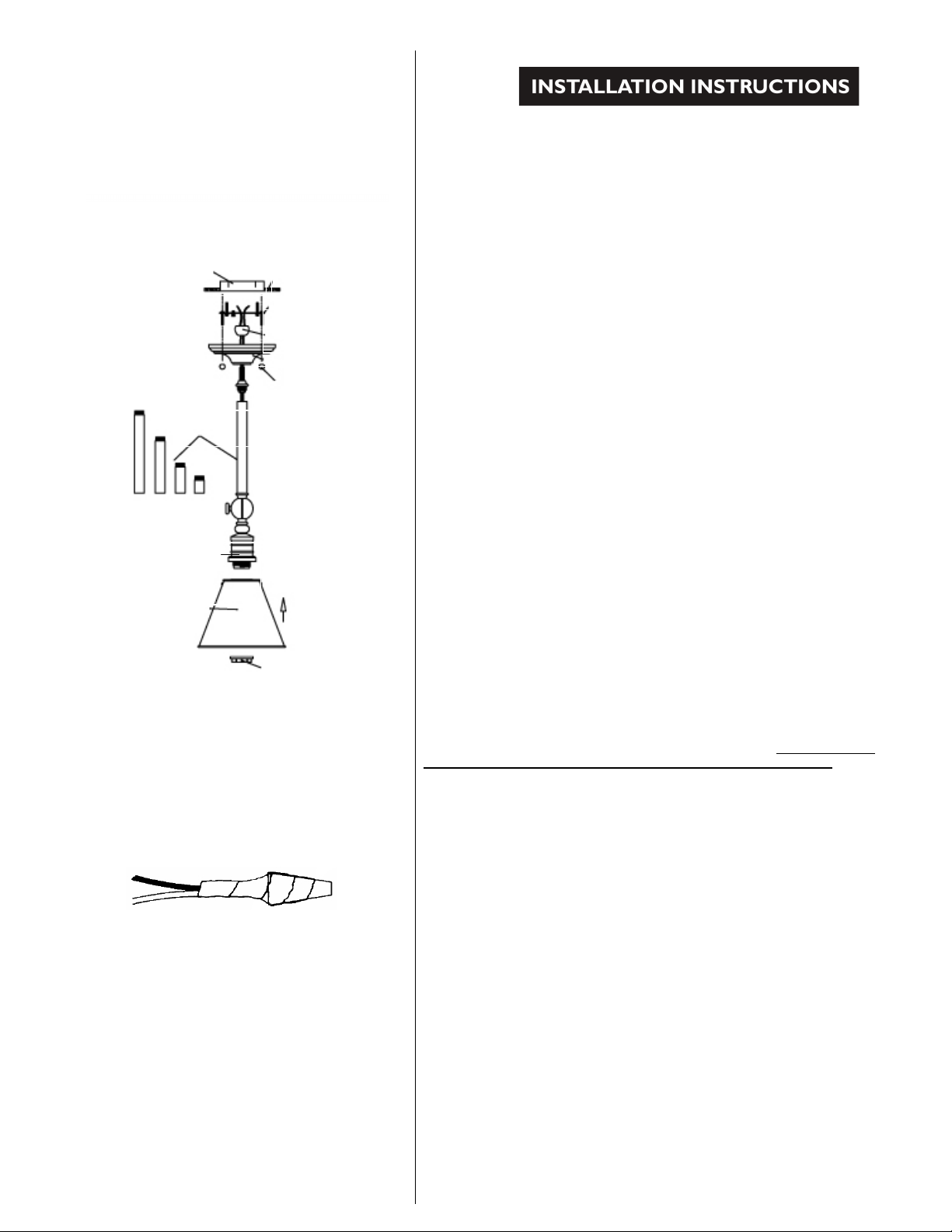
3. Pull the wires through the stems(3”, 6”,12” & 2@18”), twist the swivel onto the
stem to hold the canopy.
4. Pull the wires in the outlet box through the center hole of the crossbar. Attach
the crossbar to the outlet box. (The green ground screw should face out).
5. Fasten the green fixture wire to the green or bare copper wire in the box or
fasten it to the mounting cup with green screw provided.
NEVER FASTEN THE GROUND WIRE TO THE BLACK OR “HOT” WIRE!
FAILURE TO FOLLOW THIS INSTRUCTION COULD RESULT IN SERIOUS
INJURY OR DEATH!
6. Fasten the white fixture wire to the white wire in the outlet box. Fasten the wires
together with an approved fastener (wire nut). Starting about 1” below the fastener,
tightly wrap connection with electrical tape so that the tape seals the end of the
fastener. Make sure that there is no exposed wire or strands that could cause
a dangerous short circuit!
7. Connect the black fixture wires to the black wire in the outlet box. Fasten the
joined wires as in step 6.
8. Place the fixture over the crossbar and fasten it in place with the ball nuts.
9. Lock the shade (9608 serie with glass shade, 908 series with metal shade) to the
socket with the socket ring.
10. Install the lamp(s) light bulb(s). 9608 is rated for a100 watt type A lamp. 9611
& 9615 are rated for 150 watt type A lamp. 9908 is rated for a 75 watt type A lamp.
9911 is rated for a 100 watt type A lamp. 9915 & 9919 are rated for 150 watt type
A lamp.
DO NOT EXCEED RECOMMENDED WATTAGE !
11. Restore power to circuit at breaker or fuse box.
Fixture
Ceiling
Swivel
Stem (s)
Crossbar
Outlet
Box
Ball But
Page 2
GERAL
1. Para garantir o sucesso da instalação do dispositivo elétrico, as instruções a
seguir e diagrama (s) deve ser lido e compreendido.
2. Todas as ligações eléctricas devem ser feitas de acordo com o National
Código elétrico e códigos locais e ordenanças. Se você não tiver certeza dos
métodos de instalar fiação elétrica e dispositivos elétricos de iluminação
assegurar os serviços de um eletricista licenciada.
3. Ferramentas PRECISAVA: Chave de fenda de lâmina, chave de fenda
phillips, alicates conjunta de deslizamento ou pequena chave inglesa ajustável,
arame cortador/stripper, verificador atual elétrico, escada, elétrica (se instalados
no exterior) à prova de intempéries e fitas selante calafetagem ou silicone.
Nota: As salvaguardas importantes e instruções descritas nesta planilha não são
destinado a cobrir todas as condições e situações que podem ocorrer. Ele deve
ser entende-se que o senso comum, atenção e cuidados são factores que não
podem ser construídos em qualquer produto. Cautela e cuidado devem ser
fornecidos pela pessoa (s) instalando, operação e manutenção deste aparelho de
iluminação. Nota: Se o dispositivo estiver instalado ao ar livre,
para sua segurança estar certo de que os disjuntores controlar iluminação
exterior e equipamento ser disjuntor GFI.
PREPARAÇÃO PARA INSTALAÇÃO
1. DESLIGUE O CIRCUITO ELÉTRICO COMPLETO PARA QUE A
ILUMINAÇÃO ACESSÓRIO É PARA SER ANEXADO. Mover o disjuntor
apropriado para o "for a posição ou remover completamente o fusível controlando
o circuito.
2. Se um dispositivo elétrico existente está sendo substituído, remova-o e
Observe que os fios na caixa de saída do dispositivo elétrico foi anexado. NÃO
SEPARAR QUALQUER OUTRO FIOS QUE PODEM SER EM CAIXA. NÃO
DANIFIQUE O ISOLAMENTO DE FIAÇÃO MAIS VELHA. Em circunstâncias
normais o fio preto será a liderança "Quente" e o fio branco vai ser "Neutro" ou
"Comum" chumbo. Um verde ou BARE Fio de cobre é o "terreno". Em edifícios
mais antigos é sempre recomendável Reconfirme a polaridade de fiação.
3. Este dispositivo elétrico é projetado para ser montado em uma caixa redonda
ou octagon padrão. O caixa deve ser montada com segurança para a estrutura do
edifício.
INSTALAÇÃO DE DISPOSITIVO ELÉTRICO
1. Remova o dispositivo elétrico, vidro e partes substituida a embalagem. Antes
de descartar a embalagem, verifique de embalagem para certifique-se que todas
as peças são encontradas.
2. Retire as porcas de bola segurando a placa de montagem para a fixação.
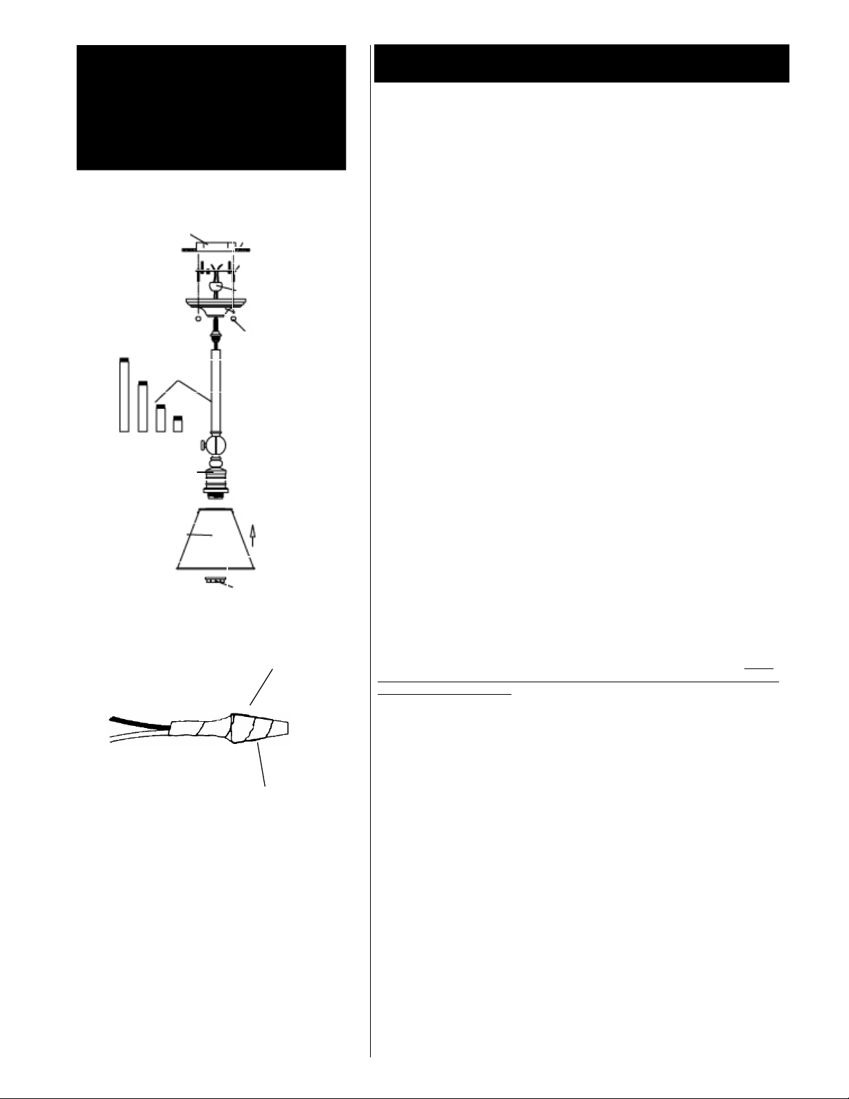
3. Puxar os fios através as hastes (3 ", 6", 12 "e 2@18"), torcer o giro para o
tronco para segurar o dossel.
4. Puxe os fios na caixa de saída através do orifício central da trave. Anexar
o crossbar para a caixa de saída. (O parafuso terra verde deve enfrentar).
5. Prenda o fio verde acessório para o fio de cobre verde ou nua na caixa ou
Prenda-o para a Copa de montagem com parafuso verde fornecido.
NUNCA PRENDA O FIO DE TERRA PARA O PRETO OU FIO "QUENTE"!
NÃO SEGUIR ESTA INSTRUÇÃO PODE RESULTAR EM GRAVES
LESÕES OU MORTE!
6. Prenda o fio branco acessório para o fio branco na caixa de saída. Prender os
fios juntamente com um fixador aprovado (porca de fio). A cerca de 1 "abaixo o
fixador, firmemente quebra conexão com fita isolante para que a fita sela o fim do
fixador. Certifique-se de que não há fios expostos ou vertentes que
poderiam causar um curto-circuito perigoso!
7. Conecte os fios preto acessório para o fio preto na caixa de saída. Prenda os
fios ingressou como na etapa 6.
8. Coloque a fixação sobre a trave e prenda-o em local com as porcas de bola.
9. Bloquear a sombra (9608 serie com sombra de vidro, 908 série com sombra
metal) para o soquete com o anel de soquete.
10. Instale o light bulb(s) de lâmpada (s). 9608 é avaliado por tipo de watt a100
uma lâmpada. 9611 & 9615 são classificados por tipo de 150 watts uma lâmpada.
9908 é avaliado para um tipo de 75 watts uma lâmpada. 9911 é avaliado para um
tipo de 100 watts uma lâmpada. 9915 & 9919 são classificados por tipo de 150
watts uma lâmpada.
NÃO SUPERIOR A POTÊNCIA RECOMENDADA!
11. Restaure a energia ao circuito no disjuntor ou fusível caixa.
Acessório
Teto
Giro
Hastes
Trave
Caixa de
saída
Bola mas
Fixador
aprovado
(porca de flo)
Fita Isolante
Anel de
soquete
Cúpula
INSTRUÇÕES DE INSTALAÇÃO
 Loading...