

Page 1
LRF-3300S Ultrasonic Transit-time Flow meter
- 1 -
Page 2
LRF-3300S Ultrasonic Transit-time Flow meter
Warning
May cause injury.
Attention
May damage the flow meter.
Notice
Thank you for choosing the LRF-3300S Ultrasonic Flow meter.
Place read the instruction manual carefully before you use the flow meter to avoiding the damage to the flow
meter or improper use.
Some of the instructions may be different to the flow meters you purchased, depending on configuration
requirements, otherwise, there is no indication about the product design and upgrade requirement in the
instructions, please refer to the version number, as well as the appendix.
- 1 -
Page 3
LRF-3300S Ultrasonic Transit-time Flow meter
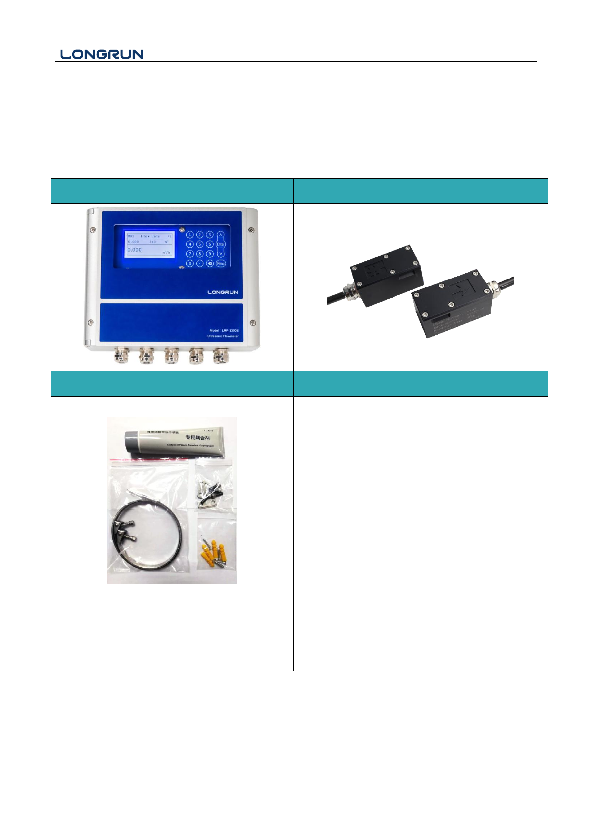
Transmitter (Electronic)
Transducers (Sensor)
Accessories
Document
1. Coupling Compound
2. Pipe straps
3. Screws and plastic bushings
1. Instruction Manual
2. Packing List
3. Position Drawing
4. Calibration Certificate
Product Components
Inspection should be made before installing the Flow meter. Check to see if the spare parts are in accordance with
the packing list. Make sure that there is no damage to the enclosure due to a loose screw or loose wire, or other
damage that may have occurred during transportation. Any questions, please contact your representative
immediately.
- 2 -
Page 4

LRF-3300S Ultrasonic Transit-time Flow meter
Content
1. Transmitter Installation and Connection .......................................................................................................... -5-
1.1. Transmitter Installation .......................................................................................................................... -5-
1.2. Wire Connecting .................................................................................................................................. - 6 -
1.2.1 Power supply option .................................................................................................................. - 6 -
1.2.2 Transmitter Wiring ..................................................................................................................... - 6 -
1.3. Powering on ......................................................................................................................................... - 7 -
1.4. Keypad Functions ................................................................................................................................ - 7 -
1.5. Keypad Operation ................................................................................................................................ - 8 -
2. Quick start...................................................................................................................................................... - 8 -
2.1. Basic settings ......................................................................................................................................... - 8 -
2.2. Measurement Site Selection................................................................................................................. - 10 -
3. Transducer Installation ................................................................................................................................ - 12 -
3.1. Transducer Installation ...................................................................................................................... - 12 -
3.1.1 Transducer Spacing .................................................................................................................. - 12 -
3.1.2 Transducer Mounting Methods ................................................................................................ - 12 -
3.1.3 V Method ................................................................................................................................. - 12 -
3.1.4 Z Method ................................................................................................................................. - 13 -
3.2. Transducer Mounting Inspection ....................................................................................................... - 14 -
3.2.1 Signal Strength ......................................................................................................................... - 14 -
3.2.2 Signal Quality (Q value) .......................................................................................................... - 14 -
3.2.3 Total Time and Delta Time ...................................................................................................... - 14 -
3.2.4 Transit Time Ratio ................................................................................................................... - 14 -
3.2.5 Warnings .................................................................................................................................. - 15 -
4. Operating Instructions ................................................................................................................................. - 16 -
4.1. System Normal Identification ............................................................................................................ - 16 -
4.2. Low Flow Cutoff Value ..................................................................................................................... - 16 -
4.3. Zero Settings ...................................................................................................................................... - 16 -
4.4. Scale Factor ....................................................................................................................................... - 16 -
4.5. System Lock ...................................................................................................................................... - 17 -
4.6. 4 ~ 20mA Current Loop Output ......................................................................................................... - 17 -
4.7. Frequency Output .............................................................................................................................. - 17 -
4.8. Totalizer Pulse Output ....................................................................................................................... - 18 -
4.9. Alarm Programming .......................................................................................................................... - 18 -
4.11. 4-20mA Analog Output Calibration ................................................................................................... - 18 -
4.12. SD Card Operation .......................................................................................................................... - 19 -
- 3 -
Page 5

LRF-3300S Ultrasonic Transit-time Flow meter
4.12.1 Specifications ......................................................................................................................... - 19 -
4.12.2 Install or Remove the SD card while the meter is powered on .............................................. - 19 -
4.13. ESN .................................................................................................................................................. - 20 -
5. Windows Display Explanations ................................................................................................................... - 21 -
5.1. Windows Display Codes .................................................................................................................... - 21 -
5.2. Display Explanations ......................................................................................................................... - 23 -
6. Error Diagnoses ........................................................................................................................................... - 40 -
6.1. Table 1. Error Codes and Solutions (during operation) ..................................................................... - 40 -
6.2. Frequently Asked Questions and Answers ......................................................................................... - 41 -
7. Product Overview ........................................................................................................................................ - 42 -
7.1. Introduction ....................................................................................................................................... - 42 -
7.2. Features of LRF-3300S ...................................................................................................................... - 42 -
7.3. Theory of Operation .......................................................................................................................... - 42 -
7.4. Applications ....................................................................................................................................... - 43 -
7.5. Specifications ..................................................................................................................................... - 44 -
8. Appendix3 – Serial Interface Network Use and Communications Protocol ................................................ - 45 -
8.1. Overview ........................................................................................................................................... - 45 -
8.2. Serial port definitions ........................................................................................................................ - 45 -
8.3. Direct connection via RS232 to the host device ................................................................................ - 46 -
8.4. Communications protocol and the use ............................................................................................... - 46 -
8.4.1 HL Protocol .............................................................................................................................. - 46 -
8.4.2. MODBUS-I Communication Protocol .................................................................................... - 48 -
9. Appendix6 - Flow Application Data ............................................................................................................ - 54 -
9.1. Sound Velocity and Viscosity for Fluids Commonly Used ................................................................ - 54 -
9.2. Sound Velocity for Various Materials Commonly Used .................................................................... - 55 -
9.3. Sound Velocity in Water (1 atm) at different temperatures ................................................................ - 56 -
Update Information:
__________________________________________________________________________________________
__________________________________________________________________________________________
__________________________________________________________________________________________
__________________________________________________________________________________________
- 4 -
Page 6
LRF-3300S Ultrasonic Transit-time Flow meter
Attention
When installing please ensure the front cover is secure and will not fall open.
1. Transmitter Installation and Connection
1.1. Transmitter Installation
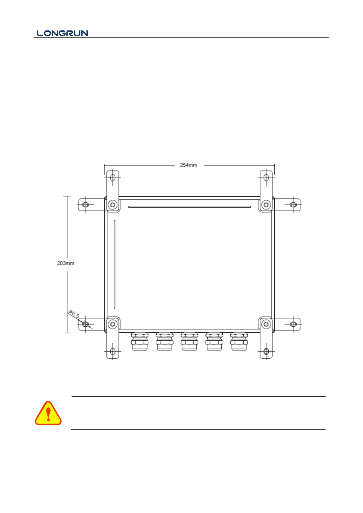
There is a "Position Drawing" in the packing.
Please use it as a template in the place that you are going to install the flow meter. Choose the corresponding to
the four mounting holes to drill at the screw position shown on the drawing with the 6 mm drill.
Take out the enclosed screws and make the 4 attaching lugs installed in the position you drill the holes. Insert the
plastic bushings into the installing holes. Then put the flow meter into the position and screw it in.
5
Page 7
LRF-3300S Ultrasonic Transit-time Flow meter
Warning
Wire when it is power-off. Reliable grounding must be taken for the instrument before installation
and use.
Use either AC or DC power supply. Do not connect them both at the same time.
1.2. Wire Connecting
1.2.1 Power supply option
Customers should pay special attention to specify the desired power supply when wiring.
Factory standard power supply is 90 ~ 245 VAC.
To ensure the transmitter can work normally, please pay attention to the followings when wiring:
Ensure that power connections are made in accordance with the specifications shown on the transmitter.
Transmitters can be powered by two different power supplies: 90 ~ 245VAC or 10-36VDC.
1.2.2 Transmitter Wiring
Once the electronics enclosure has been installed, the flow meter wiring can be connected.
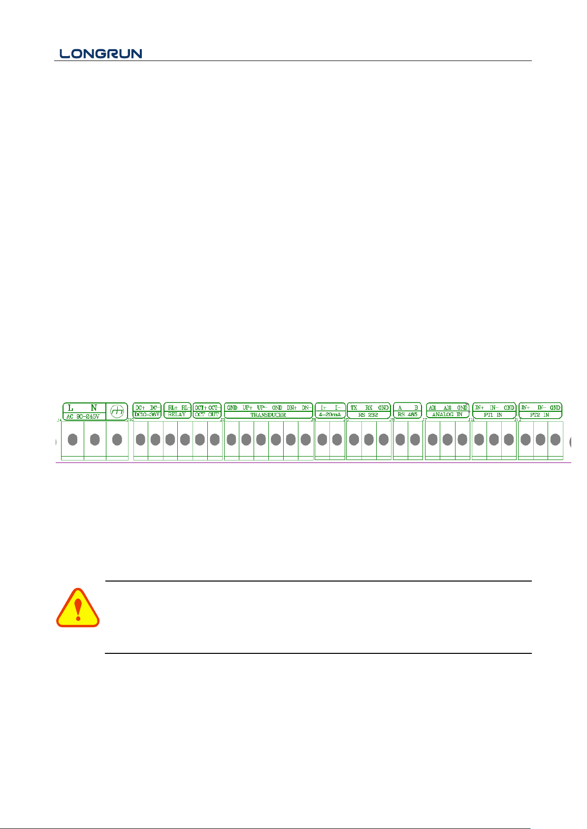
Open the case, you will find the Power board wiring ports, from left to right, are as follows;
Connect to AC power (90-245V), DC power (10-36V), Relay Output, OCT Output, Transducer wiring, 4-20mA
Output, RS232 Output, RS485 Output, Analog Input.
For double-shielded transducer cable: "-" on the Blue wire, "+" on the Brown wire and "shield" on the Black
shield wire.
Refer to the below diagram for specific connection:
Brown - Up+、DN+
Blue - Up-、DNBlack - GND
- 6 -
Page 8
LRF-3300S Ultrasonic Transit-time Flow meter
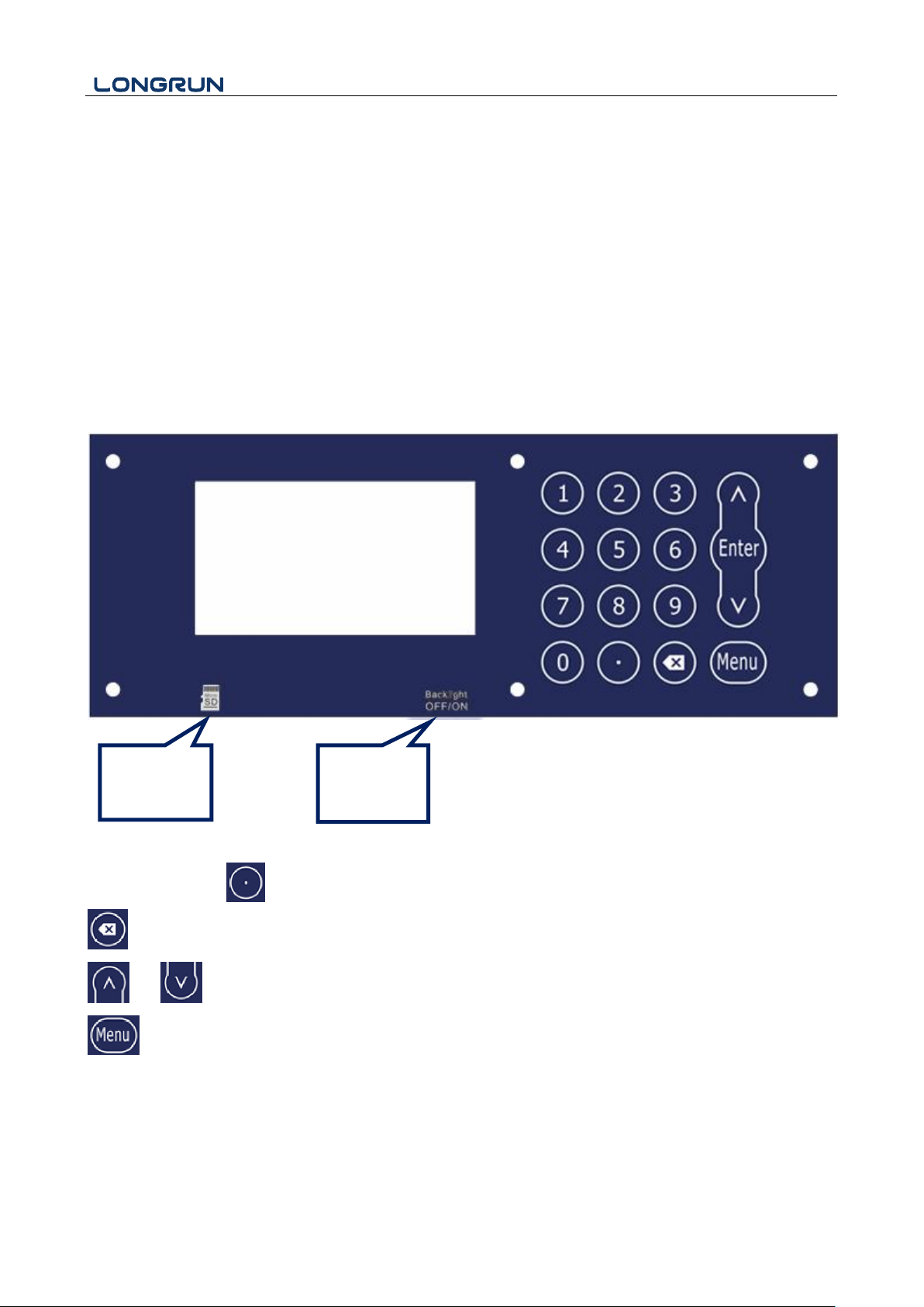
SD Card
position
Black light
Switch
1.3. Powering on
As soon as the flow meter is switched on, the system will run automatically according to the last input parameters.
If the installation is accomplished when system is switched on, gain adjustment can be monitored in Window M04.
After code "*R" are displayed on the upper right corner of the screen, the system will activate the normal
measurement condition automatically. It is indicated by code "*R" on the upper left corner of the screen.
If it is the first time to use or install on a new site, the customer need to input the new installation site parameters.
Any parameters which are set by user will be saved permanently until they are changed by the user.
When the user modifies the parameters and removes the transducers, the meter will recalculate automatically, and
operate normally with the parameters.
The flow meter can always complete all tasks at the same time. The tasks (Including measurement, output, etc)
will be carried out as usual, no matter in which display window.
1.4. Keypad Functions
Numbers “0~9” and Input Numbers or Menu Code
Backspace or delete characters to the left or back to the previous menu.
and Return to the last menu or open the next menu. Acts as "+" and "-" are used to enter numbers.
Select a menu. Press this key first, then input two menu numbers to display the selected menu.
- 7 -
Page 9
LRF-3300S Ultrasonic Transit-time Flow meter
Attention
Generally, press
Enter
key first if operator wants to enter "modify" status. If the "modify" is still not
possible even after pressing the
Enter
key, it means that system is locked by a password. To
"Unlock" it, select "Unlock" in Window M54 and enter the original password.
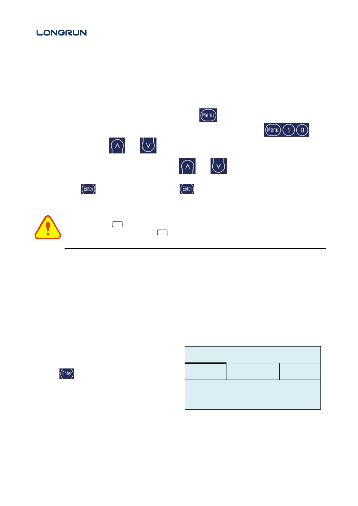
Step1. Pipe Size Settings
Find M10, enter the pipe size, the outer diameter of the
pipe and the pipe thickness.
press the to confirm.
OD
200.0
mm
M10
Pipe settings
*R
Size
M.
thk
4.0
mm
1.5. Keypad Operation
The flow meter adopts the window software design to consolidate or subdivide all of the parameters entered, the
instrument setup and measurement result displays into independent windows. The operator can input parameters,
modify settings or display measurement results by "visiting" a specific menu window. Each window serial number,
or so-called window ID code, has a defined meaning. For example, Window M10 indicates the parameter input for
pipe outside diameter, while Window M14 indicates the mounting spacing between the transducers, etc. (Refer –
Windows Display Explanations).
The keypad shortcut to visit a specific window is to press the key at any time, then input the 2-digit
window ID code. For example, to input or check the pipe outside diameter, just press the keys
for window ID code 10. Use and to switch.
Another method to visit a particular window is to press and to scroll the screen.
You can check the corresponding parameters by visiting the Data Type Windows. If you want to modify the
parameters, press first, input the digits then press again to confirm.
2. Quick start
2.1. Basic settings
For example, let us you have a pipe of 200mm outer diameter、4mm pipe thickness, measuring medium is water,
Pipe Material is PVC with no Liner, These parameters should be operated as follows:
- 8 -
Page 10
LRF-3300S Ultrasonic Transit-time Flow meter
Step2. Pipe Material
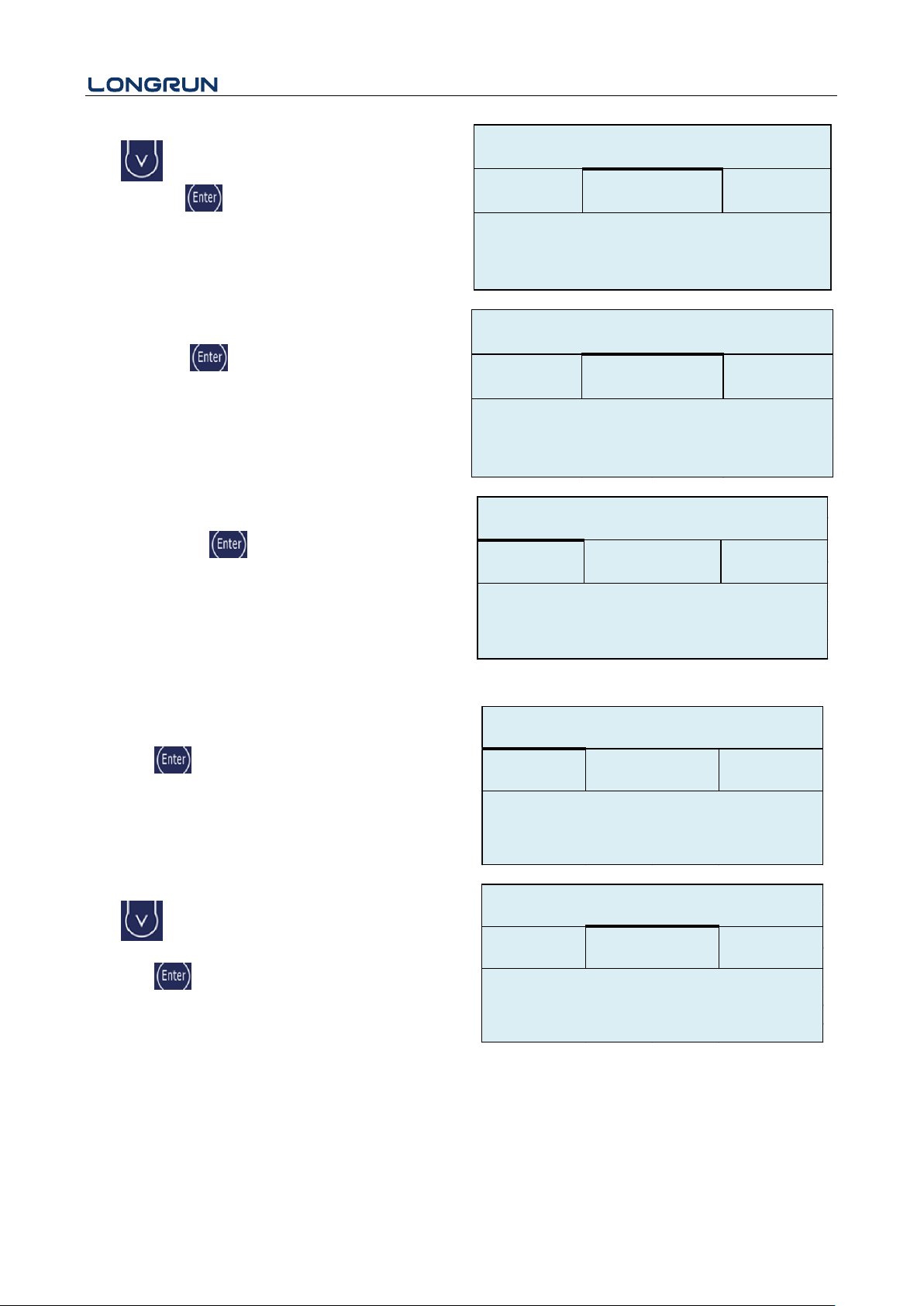
Use to switch to select the material of the pipe.
And press the to confirm.
Size
M.
M10
Pipe settings
*R
Other
3200
m/s
M.
0.PVC
Step2. Pipe Lining
Find M11, select the pipe liner. We select 0. No liner
here. Press the to confirm.
If you have liner, please select the liner material and
liner thickness.
Other
Size
M.
M11
Lining
*R
2400
m/s
M.
0.No Liner
Step 3. Fluid Type
Find M12, select the liquid medium, here we select
0.water. Press the to confirm.
M12
Medium
*R
VIS
Other
1482.0
m/s
Option
0.Water
Type
Step4. Transducer Type
Find M13, select the transducer type, here we select the
0. Clamp-On, our standard clamp on type transducer.
Press the to confirm.
Option
0.Clamp-On
M13
Transducer
*R
Type
Method
Step 5. Transducer Mounting Methods
Use to switch to select transducers mounting
method, here we select 0. V type, directly method.
Press the to confirm.
Option
M13
Transducer
*R
0.V
Type
Method
- 9 -
Page 11
LRF-3300S Ultrasonic Transit-time Flow meter
Step 6. Installation Spacing
Find M14, accurately install the transducer according to
the displayed transducer mounting spacing and the
selected mounting method.
M14
INSTL Spacing
*R
Value
154.2
mm
Step 7. Display Measurement Results
Menu 01 will display flow rate. (Subject to the real
measurement. )
M01
Flow Rate
*R
Flow
Vel.
100.2
m3/h
2.2. Measurement Site Selection
The installation of this ultrasonic flow meter is the simplest one of all kinds of flow meters. Only one suitable
measuring site needed, plug the transducers on the pipe and then start the measurement.
When selecting a measurement site, it is important to select an area where the fluid flow profile is fully developed
to guarantee a highly accurate measurement. Use the following guidelines to select a proper installation site:
Choose a section of pipe that is always full of liquid, such as a vertical pipe with flow in the upward direction
or a full horizontal pipe.
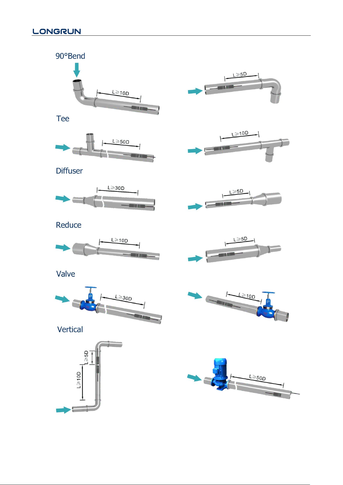
Ensure enough straight pipe length at least equal to the figure shown below for the upstream and downstream
transducers installation. Try to avoid Ensure enough straight pipe length at least equal to the figure shown
below for the upstream and downstream transducers installation.
On the horizontal pipe, the transducer should be mounted on the 9 and 3 of the pipe, avoiding the position of
6 and 12, in case of the signal attenuation caused by pipe at the bottom sediment or bubble、cavitation on the
pipe.
Ensure that the measuring site temperature is under the transducer temperature limits.
Consider the inside condition of the pipe carefully. If possible, select a section of pipe where the inside is free
of excessive corrosion or scaling.
Choose a section of sound conducting pipe.
- 10 -
Page 12
LRF-3300S Ultrasonic Transit-time Flow meter
- 11 -
Page 13
LRF-3300S Ultrasonic Transit-time Flow meter
Side view
Section
3. Transducer Installation
3.1. Transducer Installation
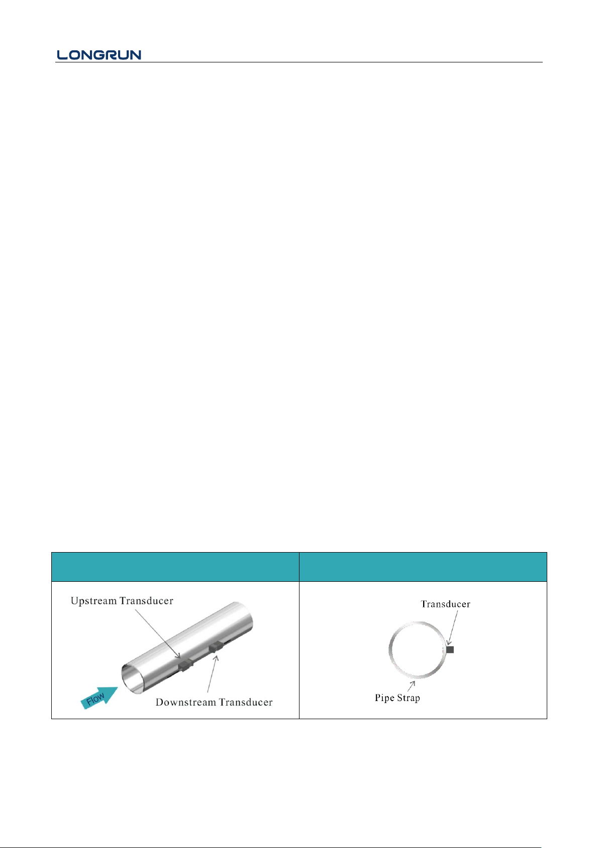
Please make sure the pipe surface where the transducers are to be mounted are all clean. Including the rust, scale
or loose paint to have a smooth surface. Choose the section and don’t forget apply the coupling compound. Apply
the coupling compound down the center of the face of each transducer as well as on the pipe surface, ensure there
are no air bubbles between the transducers and the pipe wall, and then attach the transducers to the pipe with the
straps provided and tighten them securely.
Note: The two transducers should be mounted at the pipe’s centerline on horizontal pipes.
Make sure that the transducer mounting direction is parallel with the flow.
During the installation, there should be no air bubbles or particles between the transducer and the pipe wall. On
horizontal pipes, the transducers should be mounted in the 3 o’clock and 9 o’clock positions of the pipe section in
order to avoid any air bubbles inside the top portion of the pipe. (Refer to Transducer Mounting). If the
transducers cannot be mounted horizontally symmetrically due to limitation of the local installation conditions, it
may be necessary to mount the transducers at a location where there is a guaranteed full pipe condition (the pipe is
always full of liquid).
3.1.1 Transducer Spacing
The spacing between the ENDS of the two transducers is considered as the standard transducer spacing (Refer to
MENU14). After entering the required parameters, Check the data displayed in Window M14 and adjusted the
transducers spacing according to the data displayed in Windows M14.
3.1.2 Transducer Mounting Methods
There are two mounting method, you could use depend on the measuring environment.
V method and Z method (Reflect method and Direct method).
V method is easy to installation and fit for mostly ultrasonic environment but Z method has stronger signal and
works better in the complicated measuring environment.
3.1.3 V Method
The V method is considered as the standard method. It is convenient to use, but still requires proper installation of
the transducers, contact on the pipe at the pipe’s centerline and equal spacing on either side of the centerline.
- 12 -
Page 14
LRF-3300S Ultrasonic Transit-time Flow meter
Top View
Side view
Section
Top View
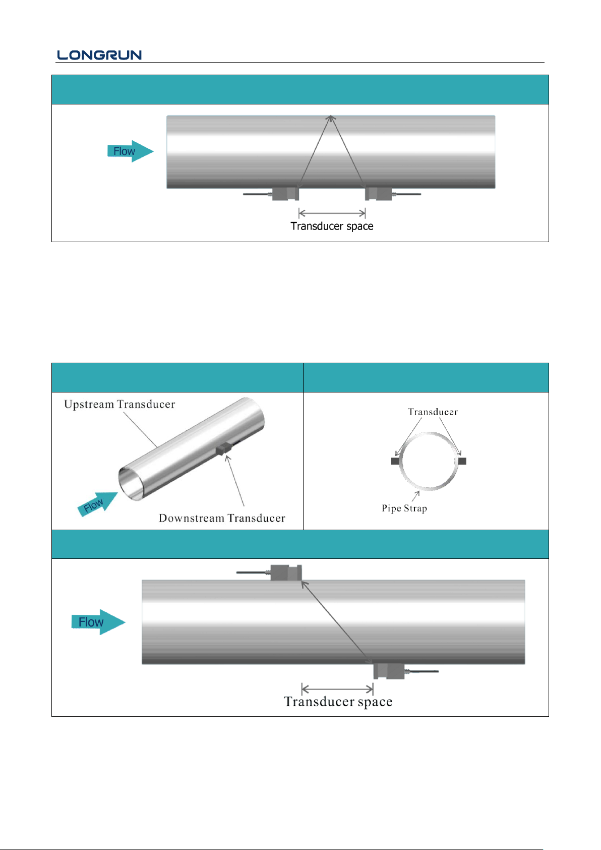
3.1.4 Z Method
The signal transmitted in a Z method installation has less attenuation than a signal transmitted with the V method
When the pipes are too large, there are some suspended solid in the fluid, or the scaling and liner are too thick.
This is because the Z method utilizes a directly transmitted (rather than reflected) signaling which transverses the
liquid only once. The Z method is able to measure on pipe diameters ranging from 100mm to 5000mm (4 inch to
200 inch) approximately. Therefore, we recommend the Z method for pipe diameters over 300mm (12 inch).
- 13 -
Page 15
LRF-3300S Ultrasonic Transit-time Flow meter
Attention
If the transit time ratio is over 100± 3%, it is necessary to check:
(1) If the parameters (pipe outside diameter, wall thickness, pipe material, liner, etc.) have
3.2. Transducer Mounting Inspection
Check to see if the transducer is installed properly and if there is an accurate and strong enough ultrasonic signal
to ensure proper operation and high reliability of the transducer. It can be confirmed by checking the detected
signal strength, total transit time, delta time as well as transit time ratio.
The "mounting" condition directly influences the flow value accuracy and system long-time running reliability. In
most instances, only apply a wide band of sonic coupling compound lengthwise on the face of the transducer and
stick it to the outside pipe wall to get good measurement results. However, the following inspections still need to
be carried out in order to ensure the high reliability of the measurement and long-term operation of the instrument.
3.2.1 Signal Strength
Signal strength (displayed in Window M04) indicates a detected strength of the signal both from upstream and
downstream directions. The relevant signal strength is indicated by numbers from 00.0 ~ 99.9. 00.0 represents no
signal detected while 99.9 represent maximum signal strength. Normally, the stronger the signal strength detected,
the longer the operation of the instrument reliably, as well as the more stable the measurement value obtained.
Adjust the transducer to the best position and check to ensure that enough sonic coupling compounds is applied
adequately during installation in order to obtain the maximum signal strength.
System normally requires signal strength over 75.0, which is detected from both upstream and downstream
directions. If the signal strength detected is too low, the transducer installation position and the transducer
mounting spacing should be re-adjusted and the pipe should be re-inspected. If necessary, change the mounting
method to be Z method.
3.2.2 Signal Quality (Q value)
Q value is short for Signal Quality (displayed in Window M04). It indicates the level of the signal detected. Q
value is indicated by numbers from 00 ~ 99. 00 represents the minimum signal detected while 99 represent the
maximum. Normally, the transducer position should be adjusted repeatedly and coupling compound application
should be checked frequently until the signal quality detected is as strong as possible.
3.2.3 Total Time and Delta Time
"Total Time and Delta Time", which displays in Window M04, indicates the condition of the installation. The
measurement calculations in the Flow meter are based upon these two parameters. Therefore, when "Delta Time"
fluctuates widely, the flow and velocities fluctuate accordingly, this means that the signal quality detected is too
poor. It may be the resulted of poor pipe-installation conditions, inadequate transducer installation or incorrect
parameter input.
Generally, "Delta Time" fluctuation should be less than ±20%. Only when the pipe diameter is too small or
velocity is too low can the fluctuation be wider.
3.2.4 Transit Time Ratio
Transit Time Ratio indicates if the transducer mounting spacing is accurate. The normal transit time ratio should
be 100+/-3 if the installation is proper. Check it in Window M04.
- 14 -
Page 16
LRF-3300S Ultrasonic Transit-time Flow meter
been entered correctly,
(2) If the transducer mounting spacing is accordance with the display in Window M14,
(3) If the transducer is mounted at the pipe’s centerline on the same diameter,
(4) If the scale is too thick or the pipe mounting is distorted in shape, etc.
3.2.5 Warnings
(1) Pipe parameters entered must be accurate; otherwise the Flow meter will not work properly.
(2) During the installation, apply enough coupling compounds in order to stick the transducers onto the
pipe wall. While checking the signal strength and Q value, move the transducers slowly around the
mounting site until the strongest signal and maximum Q value can be obtained. Make sure that the
larger the pipe diameter, the more the transducers should be moved.
(3) Check to be sure the mounting spacing is accordance with the display in Window M14 and the
transducer is mounted at the pipe’s centerline on the same diameter.
(4) Pay special attention to those pipes that formed by steel rolls (pipe with seams), since such pipe is
always irregular. If the signal strength is always displayed as 0.00, that means there is no signal
detected. Thus, it is necessary to check that the parameters (including all the pipe parameters) have
been entered accurately. Check to be sure the transducer mounting method has been selected properly,
the pipe is not worn-out, and the liner is not too thick. Make sure there is indeed fluid in the pipe or
the transducer is not too close to a valve or elbow, and there are not too many air bubbles in the fluid,
etc. With the exception of these reasons, if there is still no signal detected, the measurement site has
to be changed.
(5) Make sure that the Flow meter is able to run properly with high reliability. The stronger the signal
strength displayed, the higher the Q value reached. The longer the Flow meter runs accurately, the
higher the reliability of the flow rates displayed. If there is interference from ambient electromagnetic
waves or the signal detected is too poor, the flow value displayed is not reliable; consequently, the
capability for reliable operation is reduced.
(6) After the installation is complete, power on the instrument and check the result accordingly.
- 15 -
Page 17

LRF-3300S Ultrasonic Transit-time Flow meter
4. Operating Instructions
4.1. System Normal Identification
If the letter "*R" displays on the screen, it indicates system normal.
If the letter "D" is displayed, it indicates that system is adjusting the signal gain prior to the measurement. Also, it
means system normal. Only when the adjustment takes too long without stopping, can system be identified as
abnormal.
Letter "E" indicates no signal is being detected. Check the transducer wiring connections are correct, the
transducers are installed firmly, etc.
For further information, please refer to "Error Diagnosis".
4.2. Low Flow Cutoff Value
The data in M21 is Low Flow Cutoff Value. If the flow rate falls below the low flow cutoff value, the flow
indication is driven to zero. This function can prevent the flow meter from displaying flow as "0"after a pump was
shut down, but there is still liquid movement in the pipe, which will result in cumulative error. Generally, 0.03m/s
is recommended to enter as the low flow cutoff point.
The low flow cutoff value has no relation to the measurement results once the velocity increases over the low flow
cutoff value.
4.3. Zero Settings
Once zero flow occurs, a zero point may indicate on each measuring instrument, but the displayed measuring
value is not equal to "0", this value indicates "Zero". To any measuring instrument, the smaller the "Zero" is, the
better the quality is. Conversely, if the Zero is too big, that indicates the quality of the instrument is poor.
If the zero set point is not at true zero flow, a measurement difference may occur. The smaller the physical
measurement capacity is, the larger the measurement difference from the zero point will exist. Only when zero
point reduced to a definite degree, as compared with the physical measurement capacity, can the measuring
difference from zero point be ignored.
For an ultrasonic Flow meter, the measurement error from zero point cannot be ignored under low flow conditions.
It is necessary to perform a static zero set calibration to improve low flow measurement accuracy.
Cutoff Zero
In Window M22- Cutoff- 1.Yes, window will show the “success ” and back to M01 when you cut off the zero
point successfully.
Performing Set Zero
In Window M22- Reset
4.4. Scale Factor
Scale factor refers to the ratio between "actual value" and "reading value". For example, when the measurement is
2.00, and it is indicated as 1.98 on the instrument, the scale factor reading is 2/1.98. This means that the best scale
factor constant is 1. However, it is difficult to keep the scale factor as "1" on the instrument especially in batch
productions. The difference is called "consistency".
During operation, there still exists possible difference in pipe parameters, etc. The "scale factor" may be necessary
when used on different pipes. Thus, scale factor calibration is specially designed for calibrating the differences
that result from application on different pipes. The scale factor entered must be one that results from actual flow
calibration. The scale factor can be input in Window M26.
- 16 -
Page 18
LRF-3300S Ultrasonic Transit-time Flow meter
4.5. System Lock
System lock is intended to prevent operation error due to tampering by unauthorized personnel.
M54 is for system lock, unlock it by using the selected password only. If "lock” is displayed on the screen, then
enter the correct password.
Keep the password in mind or recorded in a safe place, otherwise the instrument cannot be used.
4.6. 4 ~ 20mA Current Loop Output
With a current loop output exceeding an accuracy of 0.1%, the flow meter is programmable and configurable with
outputs such as 4 ~ 20mA or 0 ~ 20mA selected in Menu 32. For details, please refer to Menu 32 in "Window
Display Explanations".
In Window M32- Range- LowL, enter a 4mA flow value. Enter the 20mA flow value in Window M32Range-UpperL. For example, if the flow range in a specific pipe is 0 ~ 1000m3/h, enter 0 in Window M32 and
1000 in Window M32. If the flow ranges from -1000 ~ 0 ~ 2000m3/h, configure the 20 ~ 4 ~ 20mA output by
selecting in Window M32 when flow direction is not an issue. Enter 1000 in Window M32 LowL and 2000 in
Window M32 UpperL. When flow direction is an issue, module 0 ~ 4 ~ 20mA is available. When the flow
direction displays as negative, the current output is in range of 0 ~ 4mA, whereas the 4 ~ 20mA is for the positive
direction. The output module options are displayed in Window M32.
Calibrating and testing the current loop is performed in Window M32-Check. Complete the steps as follows:
Use and to switch. "check 4mA", "check 8mA", "check 16mA", "check 20mA" readings, connect
an ammeter to test the current loop output and calculate the difference. Calibrate the 4-20mA is in M62.
4.7. Frequency Output
The flow meter is provided with a frequency output transmitter function. The high or low frequency output
displayed indicates the high or low flow rate reading. The user can reset the frequency output as well as flow rate
as the user’s actual requirements.
For example: if a pipe flow range is 0 ~ 5000m3/h, the relative frequency output required is 100 ~ 1000Hz, and
the configuration is as follows:
In Window M33-Range-LowerL (lower limit frequency output flow value), input 0;
In Window M33-Range -UpperL (upper limit frequency output flow value), input 5000;
In Window M33-Mode-Frange( frequency range), input 100、1000;
In Window M33-Mode-Option, select “a.Flow Rate”;
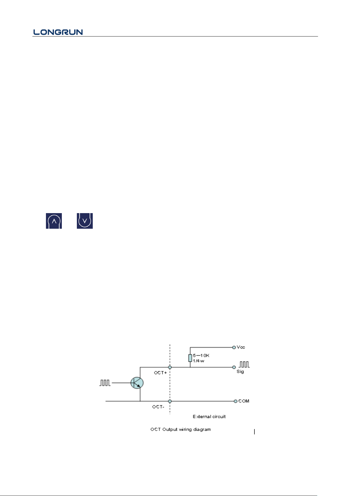
Typical OCT Output wiring diagram as below:
- 17 -
Page 19
LRF-3300S Ultrasonic Transit-time Flow meter
Attention
Each flow meter has been calibrated strictly before leaving factory. It is unnecessary to carry out
this step except when the current value (detected while calibrating the current loop) displayed in
Window M32 is not identical with the actual output current value.
Attention
Make sure to select an appropriate totalizer pulse. If the totalizer pulse is too big, the output
cycle will be too long; if the totalizer is too small, the relay will operate too faster, you may
shorten the life of the relay, as well as skip some pulses. The totalizer is recommended to
transmit within the range of 1 ~ 3 pulse per second.
4.8. Totalizer Pulse Output
Each time the flow meter reaches a unit flow, it may generate a totalizer pulse output to a remote counter.
The totalizer pulse output can be transmitted through OCT or a relay. Therefore, it is necessary to configure OCT
and the relay accordingly. (Please refer to Window M33 and M34). For example, if it is necessary to transmit the
positive totalizer pulse through a relay, and each pulse represents a flow of 10m3, the configuration is as follows:
In Window M41-Unit, select the totalizer flow unit "m3";
In Window M41-MULT, select the scale factor "e. x10";
In Window M34-Option, select "g. POS Total ";
4.9. Alarm Programming
The on-off output alarm is generated through OCT or transmission to an external circuit by opening or closing a
relay. The on-off output signal is activated under the following conditions:
(1) Signal not detected;
(2) Poor signal detected;
(3) The flow meter is not ready for normal measurement;
(4) The flow is in the reverse direction (back flow).
(5) The analog outputs exceed span by 120%.
(6) The frequency output exceeds span by 120%.
(7) The flow rate exceeds the ranges configured (Configure the flow ranges using the software alarm system.
There are two software alarms: Alarm#1 and Alarm #2.
Example 1: When flow rate exceeds 300 ~ 1000 m3/h, in order to program the relay output alarm, Complete the
steps as follows:
(1) In Menu 35, Alarm1 LowL 300;
(2) In Menu 35, Alarm1 Upper 1000;
(3) In Menu 34, Relay Setting-Option-d.Alarm1
4.11. 4-20mA Analog Output Calibration
The hardware detect window must be activated prior to calibration the Analog Output. The procedure is as
follows:
Menu 62 is for 4-20mA calibration, if you need enter the pass word to enter. With no effect to next power on, this
window will close automatically as soon as the power is turned off.
- 18 -
Page 20
LRF-3300S Ultrasonic Transit-time Flow meter
Use and to switch calibrate the current loop 4mA output. Use an ammeter to measure the output
current of current loop and adjust the displayed numbers at the same time. Watch the ammeter until it reads 4.00.
Stop at this point, the 4mA has been calibrated.
Use and to switch calibrate the current loop 20mA output. The method is the same as 4mA
calibration.
The results are automatically saved in EEPROM and won’t lose when power off.
4.12. SD Card Operation
4.12.1 Specifications
Data collection interval: any interval settings from 1 to 3600 seconds are OK according to the requirement.
Data content: date and time, flow rate, flow velocity, total flow, positive totalizer, negative totalizer.
Data storage format:
a=2017-11-16,16:21:12
b=+2.652471E+00 m3/h
c=+9.380460E-02 m/s
d=+3.520580E+02 m3
e=+3.520580E+02 m3
f=+0.000000E+00 m3
g=+0.000000E+00 GJ/h
h=+0.000000E+00 GJ
i=+0.000000E+00 GJ
j=+0.000000E+00`C
k=+0.000000E+00`CFile
system format: FAT16.
File type: plain text file (.TXT).
File number: maximum 512pcs.
It can save 120 bytes of data each time. If it is set to save once in per 5 seconds, the capacity of storing file in 24
hours is 120*3600/5*24=2073600byte≈2.1Mbyte, therefore, 1Gbyte SD card can store for days: 1024/2.1=
487.6≈487 days. When the capacity of the SD card is full, the new data will override the earliest files
automatically.
4.12.2 Install or Remove the SD card while the meter is powered on
If the operator desires to insert the SD card with power on, please remove the power with power off. The
following operation is to be used:
- 19 -
Page 21
LRF-3300S Ultrasonic Transit-time Flow meter
ATTENTION
Other Operating Refer to "6.2 Window Display Explanations".
Attention:
Do not remove the SD card from the reader while actively working with the data. Data should
be saved and stored in a separate location on the PC, and then processed form that file
location. Processing the data directly from the SD card file location on the PC could result in
losing or destroying data if the SD card is removed while still being processed.
4.13. ESN
We provide the flow meter with a unique electronic serial number to identify each flow meter for the convenience
of the manufacturer and customers. The ESN, instrument types and versions are able to view in Window M61.
- 20 -
Page 22
LRF-3300S Ultrasonic Transit-time Flow meter
Easy Introduction
A class of the menu
M0X
Display
Value and Condition
*R- System Normal
*E - Signal Not Detected
*D- Adjusting Gain
M00 Flow Totalizer
M01 Flow Rate
M02 Energy Totalizer
M03 Energy Rate
M04 Status
M1X
Installation Setting
M10 Pipe Settings
M11 Lining Settings
M12 Liquid Settings
M13 Transducer Settings
M14 Installation Space
M2X
Calibration Setting
M20 Damping
M21 Low Flow Cut off Value
M22 Zero Point Settings
M23 Energy Totalizer Settings
M24 Temperature Sensitivity Settings
M25 Automatic Flow Correction
M26 K Factor Setting
M27 Linear Calibration settings
M3X
Input and Output Settings
M30 Serial Port Parameter
M31 AI Settings
M32 4-20mA Settings
M33 OCT Settings
M34 Relay Settings
5. Windows Display Explanations
5.1. Windows Display Codes
- 21 -
Page 23
LRF-3300S Ultrasonic Transit-time Flow meter
M3X
Input and Output Settings
M35 Alarm Value Settings
M36 Flow Batch Settings
M37 Micro SD Settings
M4X
Flow Unit Opinions
M40 Metric system Units
M41 Flow Rate Units
M42 BTU Units
M43 Temperature Units
M5X
System Settings
M50 Serial Number
M51 Time and Date
M52 Beeper Setup
M53 Initial Interface Settings
M54 System Lock Settings
M55 Restore Factory Settings
M6X
Others
M60 Date Totalizer
M61 Working Timer
M62 4-20mA Calibration
M63 RTD Calibration
M64 AI Calibration
NOTE:The other menu features are retained by manufacturers.
- 22 -
Page 24
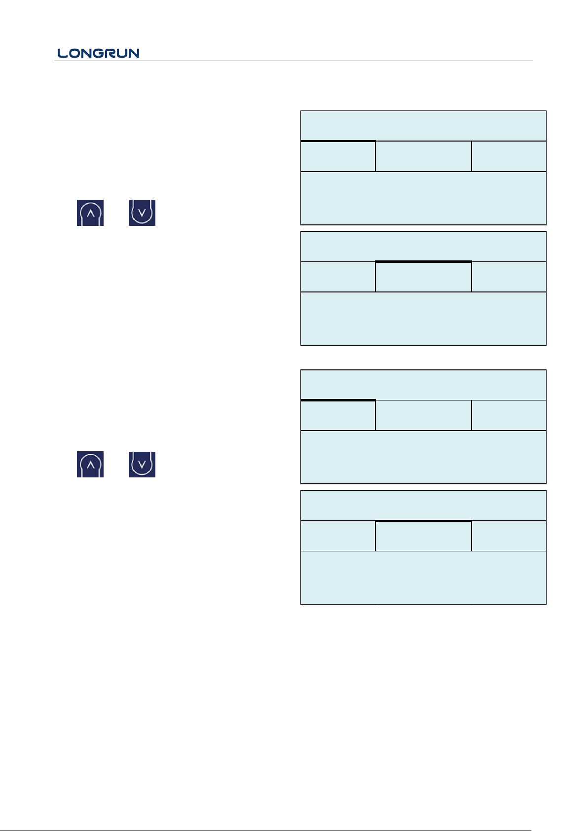
M00
Flow Total
Display Net Totalizer.
Display Positive totalizer.
Display Negative totalizer.
Use and to switch.
M01
Flow Rate
Display the Flow Rate.
Display the Velocity.
Use and to switch.
M00
Flow Total
*R
123.4
NET
POS
m
3
E+0
NEG
E+0
m
3
M00
Flow Total
*R
NET
POS
NEG
123.4
100.2
m3/h
M01
Flow Rate
*R
Flow
Vel.
3.2
m/s
M01
Flow Rate
*R
Flow
Vel.
M02
LRF-3300S Ultrasonic Transit-time Flow meter
5.2. Display Explanations
- 23 -
Page 25
LRF-3300S Ultrasonic Transit-time Flow meter
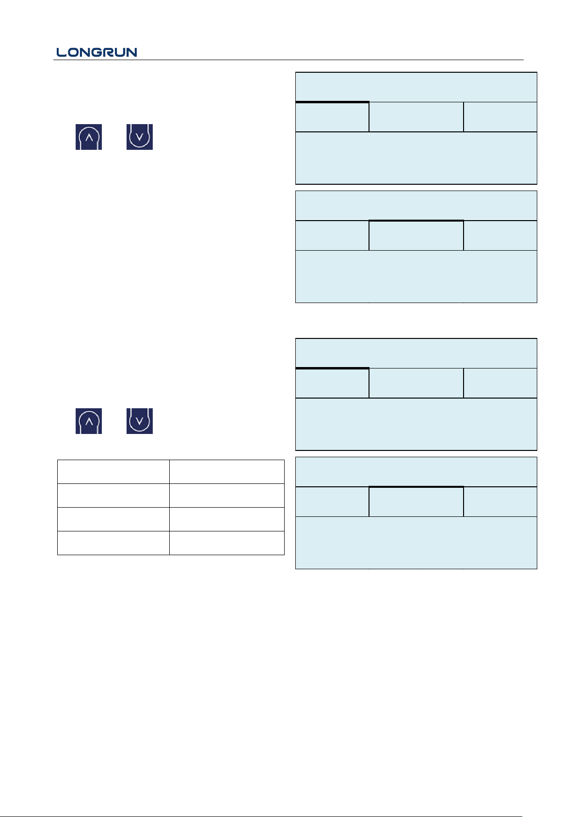
Energy Total
Display the Totalizer Heat Capacity
Display theTotalizer Cool Capacity.
Use and to switch.
NOTE:
Instrument needs energy capacity.
Heat
Cool
234.5
E+0
GJ
M02
Energy Total
*R
Heat
Cool
201.6
E+0
GJ
M02
Energy Total
*R
M03
Energy Rate
Display the Energy Rate.
Display the Inlet Water Temp and Outlet Water Temp.
Use and to switch.
0. x 0.001 (E-3)
1. x 0.01(E-2)
2. x 0.1(E-1)
3. x 1(E+0)
4. x 10(E+1)
5. x 100(E+2)
6. x 1000(E+3)
7. x 10000(E+4)
NOTE:
Instrument needs energy capacity.
234.5
E+0
GJ
M03
Energy Rate
*R
Energy
TEMP.
ΔT
-2.0
M03
Energy Rate
*R
Energy
TEMP.
(。C)InOut
7.0
9.0
M04
- 24 -
Page 26
LRF-3300S Ultrasonic Transit-time Flow meter
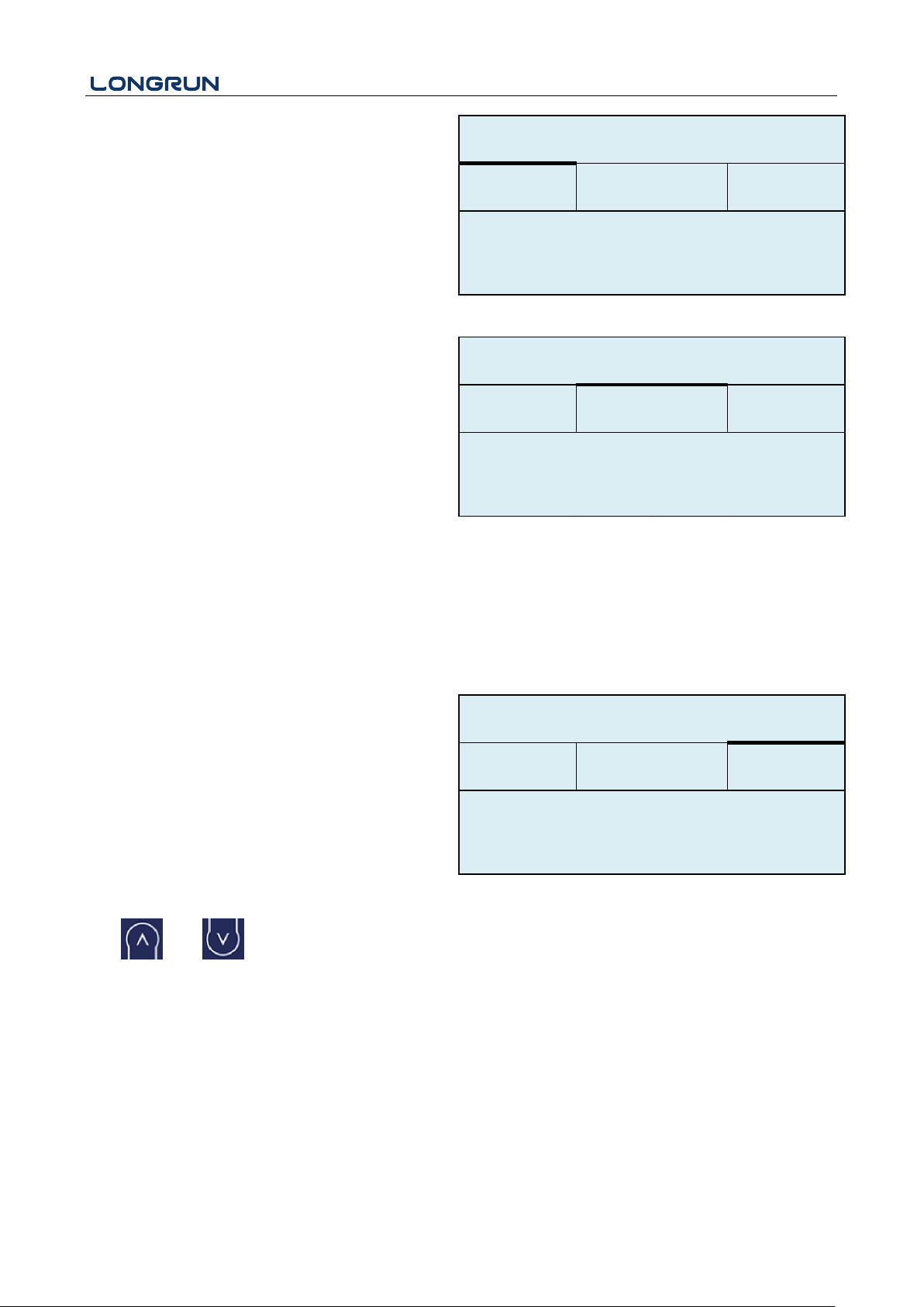
Status
Display the Signal strength, the Upstream signal
strength and Downstream signal strength.
Signal quality Q is indicated by 00 ~ 99. Therefore,
00 indicates the poorest signal while 99 indicates
the best signal. Normally, signal quality Q value
should be better than 60
Q85Up
Dn
80.0
80.1
M04
Status
*R
Signal
Sound
Time
Display the measured fluid sound velocity.
Normally this value should be approximately equal
to the entered value in Window M12. If the
difference is too large, it probably results from an
incorrect value entered in Window M12 or improper
installation of the transducers.
Display the ratio between the actual measured
transmit
time and the calculated transmit time according to
customer’s requirement. Normally the ratio should
be 100±3%. If the difference is too large, the user
should check that the parameters are entered
correctly, especially the sound velocity of the fluid
and the installation of the transducers.
This data is of no use before the system is ready.
Vel.
Ratio
*R
Signal
Sound
Time
M04
Status
1482
100%
E+0
m
3
Display the measured ultrasonic average time (unit:
us) and delta time of the upstream and downstream
(unit: ns) time. The velocity calculation in the flow
meter is based on the two readings. The delta time
is the best indication that the instrument is running
steadily. Normally the fluctuation in the ratio of the
delta time should be lower than 20%. If it is not, it is
necessary to check if the transducers are installed
properly or if the parameters have been entered
correctly.
Use and to switch.
M04
Status
*R
Signal
Sound
Time
Total
185.0
Delta
30.5
us
ns
- 25 -
Page 27
LRF-3300S Ultrasonic Transit-time Flow meter
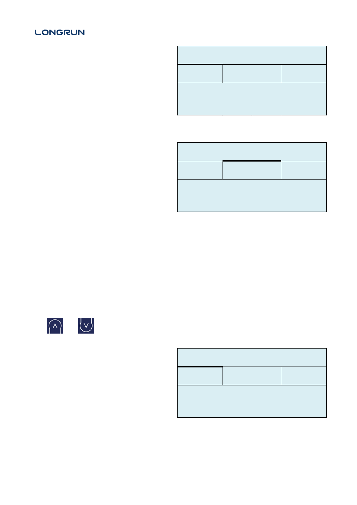
M10
Pipe settings
Enter the pipe outer diameter; the pipe outer
diameter must range from 10mm to 6000mm.
Note: Enter Either pipe outer diameter or pipe outer
perimeter
Enter the pipe wall thickness. Pipe wall thickness is
necessary.
OD
108.0
mm
M10
Pipe settings
*R
Size
M.
thk
4.0
mm
Enter pipe material. The following options are
available:
0. PVC
1. CS Carbon Steel
2. SSP Stainless Steel Pipe
3. CIP Cast Iron Pipe
4. DIP Ductile Cast Iron Pipe
5. Copper
6. Alu. Aluminum pipe
7. ACP Asbestos Cement Pipe
8. FPG Fiberglass Pipe
9. Other
Size
M.
M10
Pipe settings
*R
Other
3200
m/s
M.
0.PVC
Refer to item 9 "Other"; it is possible to enter other
materials, which are not included in previous eight
items. Once item 9 is selected, the relevant pipe
sound velocity must be entered.
Use and to switch.
M11
Lining
Enter liner thickness.
Select the Liner Material.
The following options are available:
0. No liner
1. Tar Epoxy
Size
M.
M11
Lining
*R
thk
3.0
mm
- 26 -
Page 28
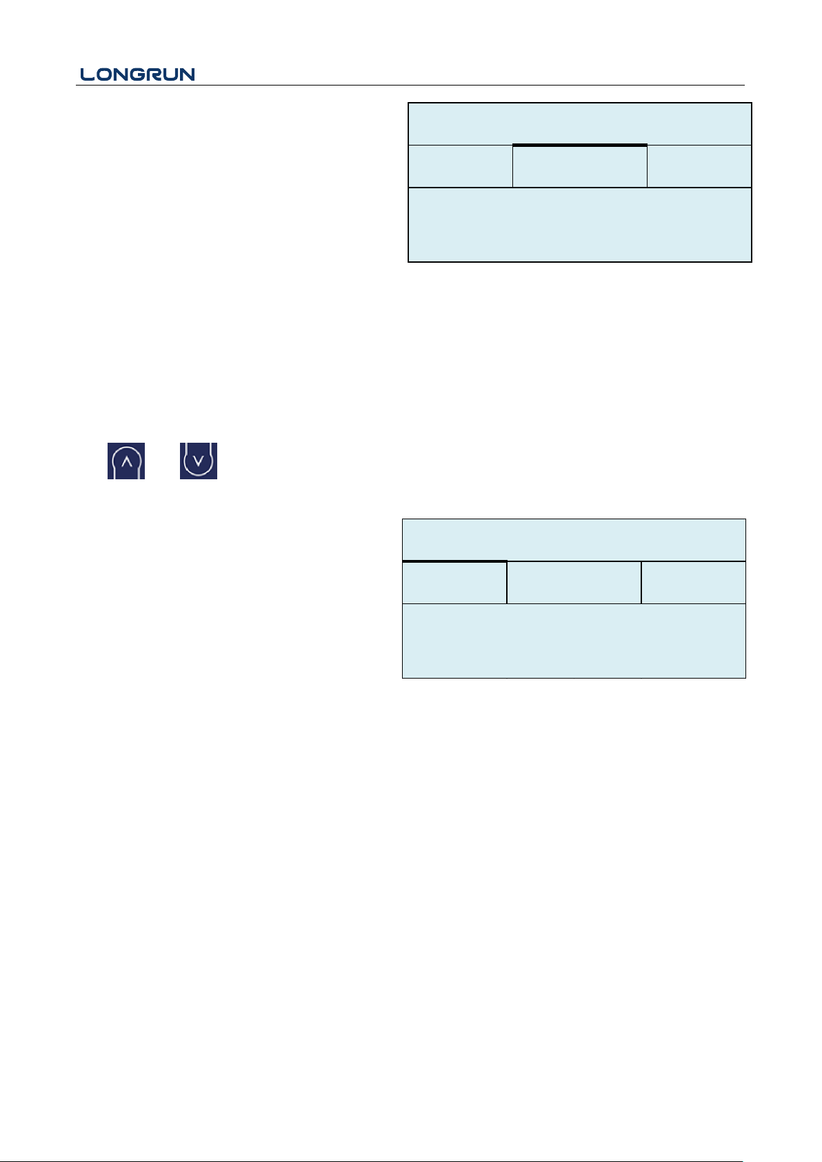
LRF-3300S Ultrasonic Transit-time Flow meter
2. Rubber
3. Mortar
4. PP Polypropylene
5. Polystryol
6. PS Polystyrene
7. Polyester
8. PE Polyethylene
9. Ebonite
10. Teflon
11. Other
Other
Size
M.
M11
Lining
*R
2400
m/s
M.
0.No Liner
Item 11 "Other" is available to enter other materials
that are not included in previous ten items. Once the
"Other" is selected, the relevant liner sound velocity
must be entered.
M12
Medium
Select measure medium.
The following options are available:
0. Water
1. Water 125 degC
2. Seawater
3. Kerosene
4. Gasoline
5. Fuel Oil
6. Crude Oil
7. Diesel Oil
8. Castor Oil
9. Peanut Oil
10. Alcohol
11. Propane (-45℃)
12. Butane (0℃)
13. Gas #93
14. Other
Item 15"Other" is available to enter other materials
M12
Medium
*R
VIS
Other
1482.0
m/s
Option
0.Water
Type
Use and to switch.
- 27 -
Page 29
LRF-3300S Ultrasonic Transit-time Flow meter
that are not included in previous ten items. Once the
"Other" is selected, the relevant liner sound velocity
must be entered.
Use and to switch.
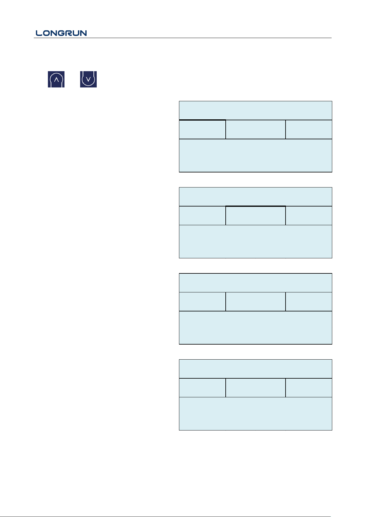
M13
Transducer
Select transducer type
The following options are available:
0. Clamp-On
1. Clamp-On S
2. Clamp-On X
3. Plus-In
4. Plus-In X
Select transducer Mounting Methods
Three mounting methods are available:
0. V Reflect method
1. Z Direct method
2. N
M14
Installation space
This value is calculated by the flow meter
The operator must mount the transducer
according to the transducer spacing displayed
(ensure that the transducer spacing is measured
precisely during installation). The system will
display the data automatically after the pipe
parameter had been entered.
M20
Damping
The damping factor ranges from 1 ~ 999 seconds.1
indicates no damping; 999 indicates the maximum
damping.
The damping function will stabilize the flow display.
Usually a damping factor of 3 to 10 is recommended
in applications.
M21
Option
0.Clamp-On
M13
Transducer
*R
Type
Method
Option
M13
Transducer
*R
0.V
Type
Method
M14
INSTL Spacing
*R
Value
20.0
mm
Value
6
M20
Damping
*R
- 28 -
Page 30
LRF-3300S Ultrasonic Transit-time Flow meter
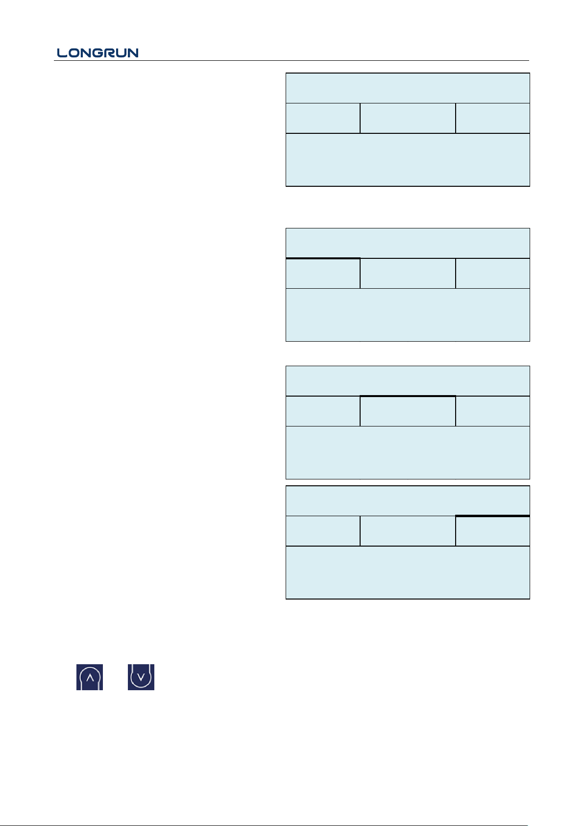
Low Vel. Cut off
Low Flow Cut off is used to make the system display
as "0" value at lower and smaller flows to avoid any
invalid totalizing. For example, if the cutoff value is
set as 0.03, system will take all the measured flow
velocity values from - 0.03 to + 0.03 as "0".
Generally, 0.03 is recommended in most
applications.
M22
Zero Settings
When fluid is in the static state, the displayed value
is called "Zero Point". When "Zero Point’ is not at
zero in the flow meter, the difference is going to be
added into the actual flow values and measurement
differences will occur in the flow meter.
Set zero must be carried out after the transducers are
installed and the flow inside the pipe is in the
absolute static state (no liquid movement in the
pipe). Thus, the "Zero Point" resulting from different
pipe mounting locations and parameters can be
eliminated. The measuring accuracy at low flow is
enhanced by doing this and flow offset is eliminated.
Select "YES"; reset "Zero Point" which was set by
the user.
This method is not commonly used. It is only
suitable for experienced operators to set zero under
conditions when it is not preferable to use other
methods. Enter the value manually to add to the
measured value to obtain the actual value. For
example:
Actual measured value =240 m3/H
Value Deviation =10 m3/H
Flow meter Display =250 m3/H
Normally, set the value as "0".
Use and to switch.
M23
Totalizer
Value
0.03
m/s
M21
Low Vel. Cutoff
*R
M22
Zero Settings
*R
Cutoff
Reset
Offset
Option
0.No
M22
Zero Settings
*R
Option
0.No
Cutoff
Reset
Offset
0.0
m3/h
M22
Zero Settings
*R
Cutoff
Reset
Offset
Value
- 29 -
Page 31
LRF-3300S Ultrasonic Transit-time Flow meter
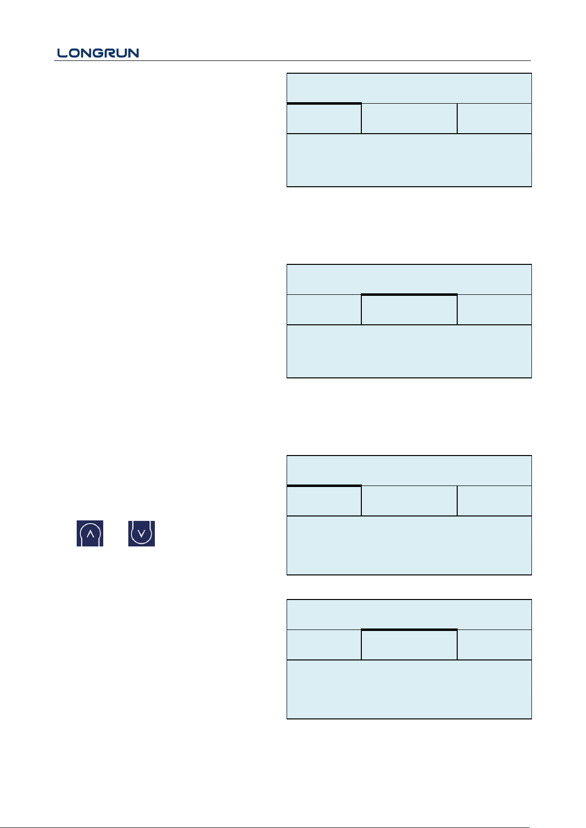
Select the totalizer type
0. POS Positive Totalizer
1. NEG Negative Totalizer
2. NET
Select energy type
0. Heat
1. Cool
Select "ON"/"OFF" to switch the totalizer.
Select the flow totalizer value you want Reset
0. POS Positive Totalizer
1. NEG
2. NET Negative Totalizer
3. All
Select the energy totalizer value you want Reset
0. Heat
1. Cool
2. All
M24
Temperature
Select Heat Input Options:
0. RTD
1. AI
Use and to switch.
Temperature Sensitivity Setting
When the delta temperature is less than the
sensitivity set, energy will not be accumulated. Set
the adjustable temperature range of 0℃ ~ 20℃. The
factory default setting is 0.2 ℃.
Select Specific Heat Options:
0. CJ128 SHC
Energy
0.Heat
0.ON
Switch
Reset
Flow
0.POS
0.ON
M23
Totalizer
*R
Energy
0.Heat
Switch
Reset
Flow
0.POS
M23
Totalizer
*R
Source
SSTV
SHC
M24
Temperature
*R
Option
0.RTD
Source
SSTV
SHC
M24
Temperature
*R
Value
0.20
。
C
- 30 -
Page 32
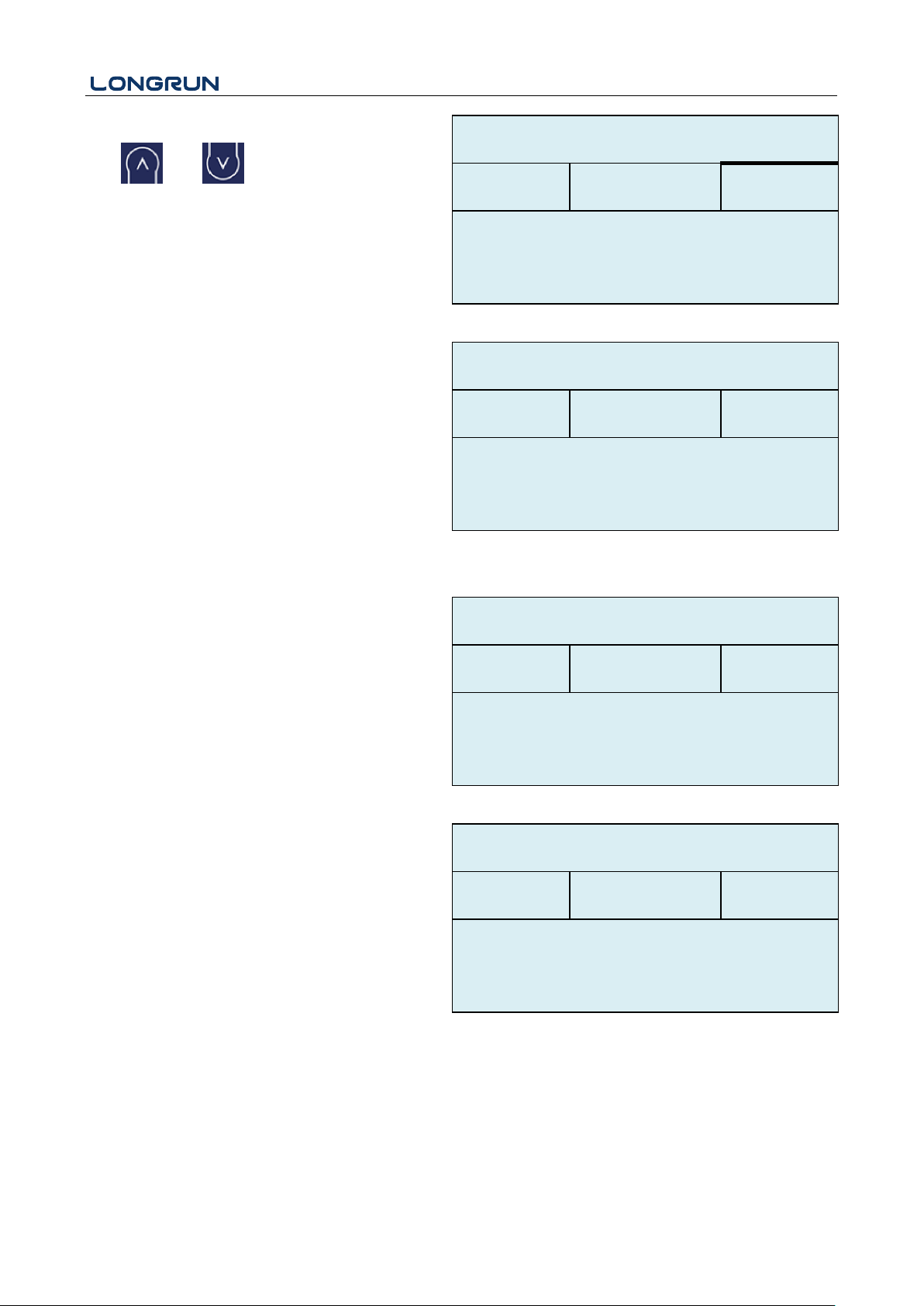
LRF-3300S Ultrasonic Transit-time Flow meter
1. Other
Use and to switch.
M25
Power Down Correction Switch
With the function of power down automation
correction switch, the flow lost in an offline session
can be estimated and automatically adjusted. The
estimate is based on the average value, which is
obtained from flow rate before going offline and
flow measured after going online the next time,
multiplied times the time period that the meter was
offline. Select "ON" to use this function, select
"OFF" to cancel this function.
M26
K Factor
The K factor is used to modify the measurement
results. The user can enter a numerical value (other
than "1") according to the actual calibration results.
M27
Correction
Sectional Correction
ON: Open the Sectional Correction Function;
OFF: Close the Sectional Correction Function
Expand only in the current period, automatically
shut down when the power is cut off. You can set 10
groups correction coefficient for sectionally
correcting measurement results. The user can input
the actual scale factor, referring to the calibration
results.
M30
RS232/RS485
Serial Port Setting
0.CJ128
m3/h
Other
4.2
KJ/m3。C
M24
Temperature
*R
Source
SSTV
SHC
Option
Option
0.ON
M25 PowerDown COMP *R
M26
K Factor
*R
Value
1.000
Option
0.ON
Value
a 0.03,1.000
M27
Correction
*R
- 31 -
Page 33
LRF-3300S Ultrasonic Transit-time Flow meter
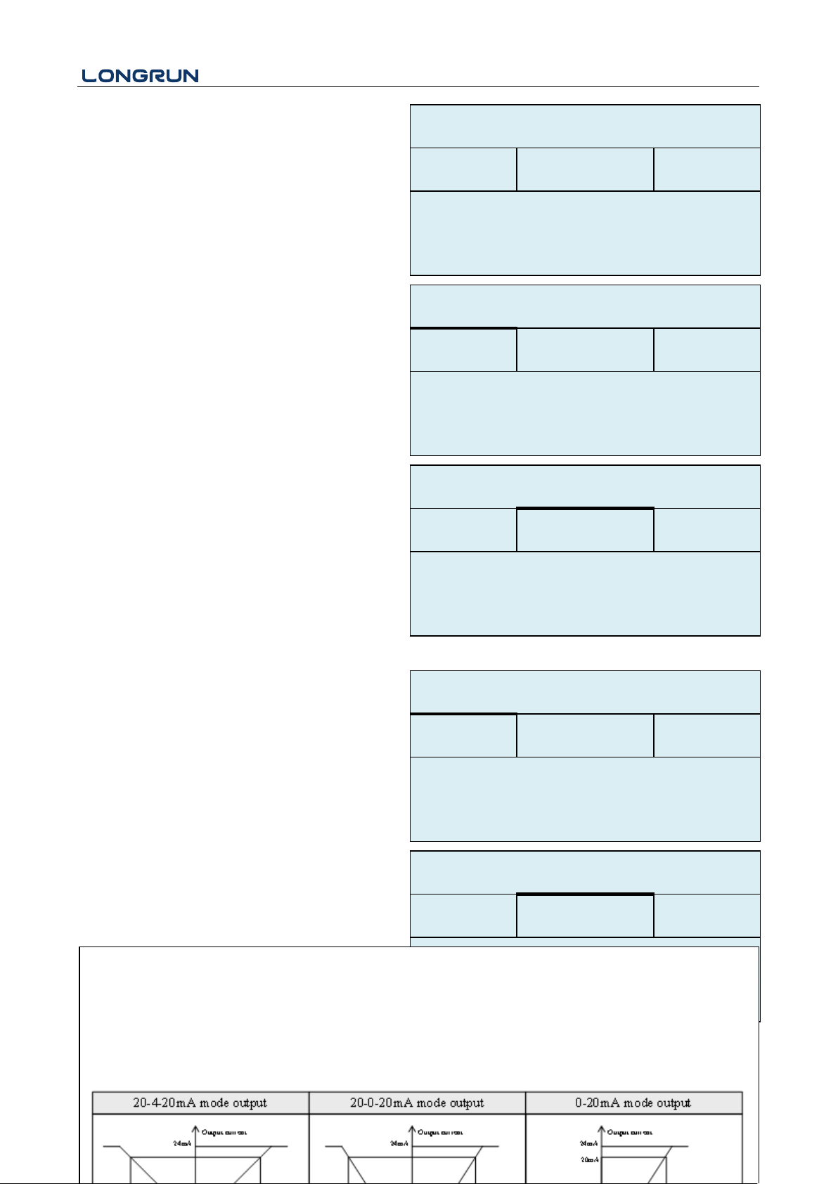
M31
AI Setting
Display analog input AI1 analog value.
Display analog input AI2 analog value.
M32
CL Setting
Current Loop Mode Options
Select the CL Range value
Set the CL output value according to the flow value
at 4mA or 0MA.
Set the CL output value according to the flow value
at 20mA.
4-20mA check opinions
a. Check 4mA
b. Check 8mA
c. Check 12mA
d. Check 20mA
Option
0.2400 None
ID
55
M30
RS232/RS485
*R
LowerL
1.0
UpperL
1000.0
M31
AI Settings
*R
AI1
AI2
LowerL
1.0
UpperL
1000.0
M31
AI Settings
*R
AI1
AI2
Option
a.4-20mA
M32
CL Settings
*R
Mode
Range
Check
Mode
Range
Check
M32
CL Settings
*R
UpperL
1000.0
m3/h
LowerL
0.0
m3/h
0. 4-20mA Output range from 4-20mA
1. 0-20mA Output range from 0-20mA
2. 0-20mAUart Be controlled by Serial Port
3. 20-4-20mA Output range from 20-4-20mA
4. 0-4-20mA Output range from 0-4-20mA
5. 20-0-20mA Output range from 20-0-20mA
6. 4-20mA -Vel Set up the CL output range from 4-20mA corresponding flow velocity
7. 4-20Ma-NRG Set up the CL output range from 4-20mA corresponding heat capacity
- 32 -
Page 34
LRF-3300S Ultrasonic Transit-time Flow meter
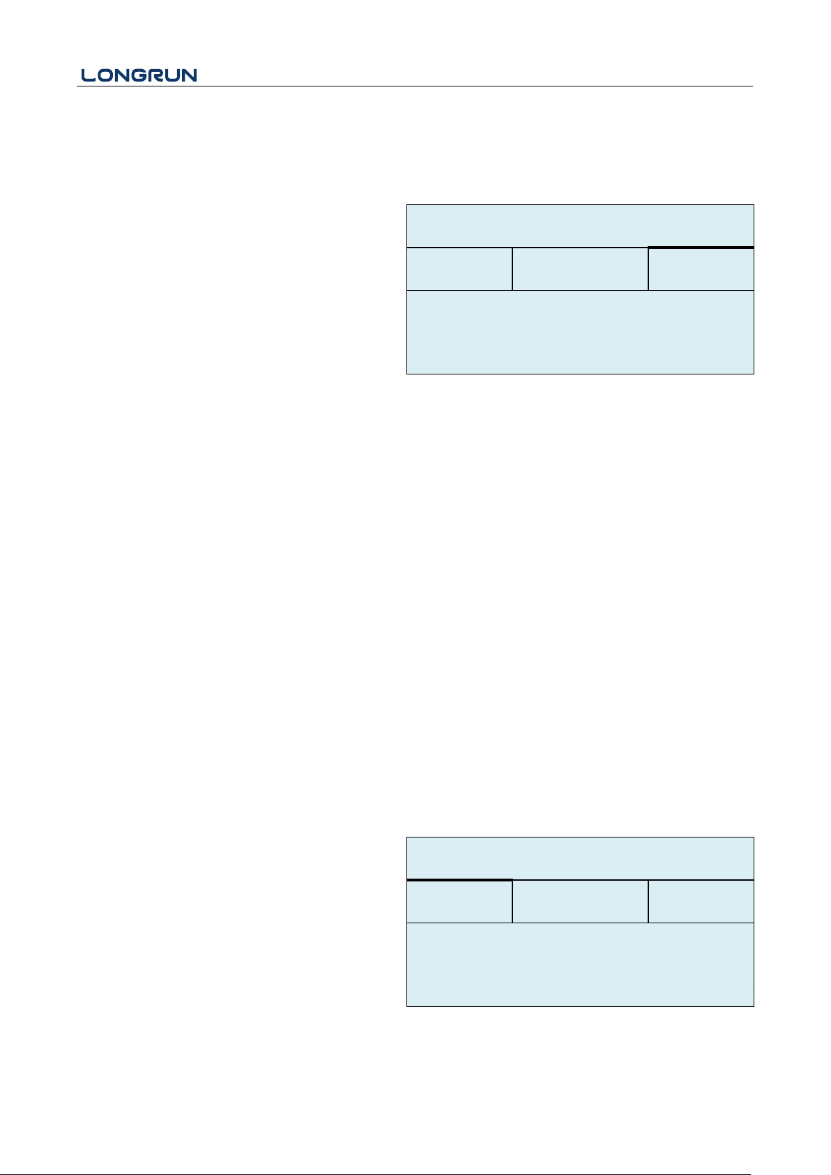
M33
OCT Setting
The following signal options are available:
a. Flow Rate
b. POS Total
c. NEG Total
d. NET Total
e. Energy Rate
f. Heat Total
g. Cool Total
h. Rationing
i. Uart CTRL
Mode
Range
Check
M32
CL Settings
*R
Option
a.Check 4mA
Option
a.Flow Rate
Frange
0-5000 Hz
M33
OCT Settings
*R
Mode
Range
Check
- 33 -
Page 35
LRF-3300S Ultrasonic Transit-time Flow meter
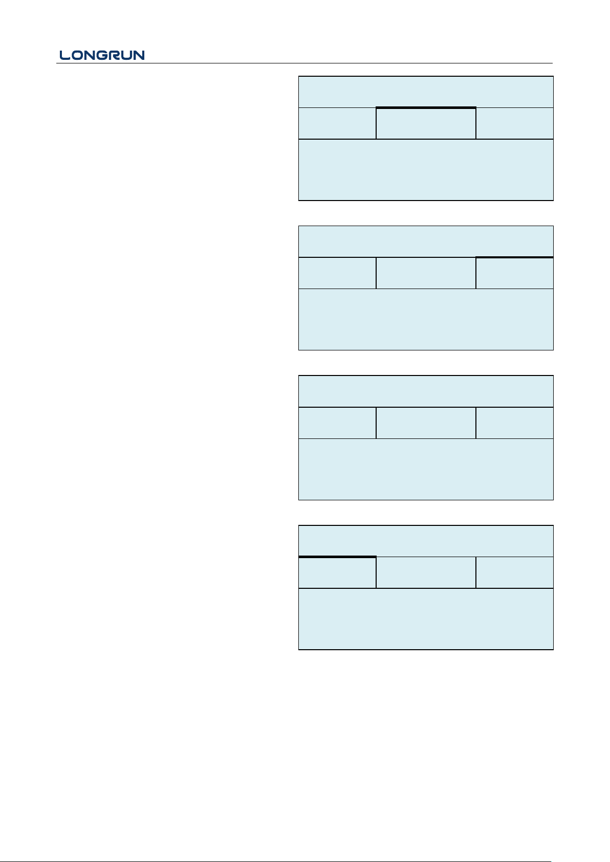
Select the OCT Range value.
OCT check opinions
a. Check 500
b. Check 1000
c. Check 3000
d. Check 5000
M34
Relay Setting
The following signal options are available:
a. No Signal
b. *E
c. Reverse
d. Alarm1
e. Alarm2
f. Ration
g. POS Total
h. NEG Total
i. NET Total
j. Not Using
M35
Alarm Setting
Enter the Lower \ alarm value, any of the measured
flow, which is lower than the low value, will activate
the alarm in the OCT hardware or relay output
signal.
Mode
Range
Check
M33
OCT Settings
*R
UpperL
1000.0
m3/h
LowerL
0.0
m3/h
Mode
Range
Check
M33
OCT Settings
*R
Option
a.Check 500
Option
a.No Signal
M34
Relay Settings
*R
LowerL
0.0
m3/h
UpperL
1000.0
m3/h
M35
Alarm Settings
*R
Alarm1
Alarm2
- 34 -
Page 36
LRF-3300S Ultrasonic Transit-time Flow meter
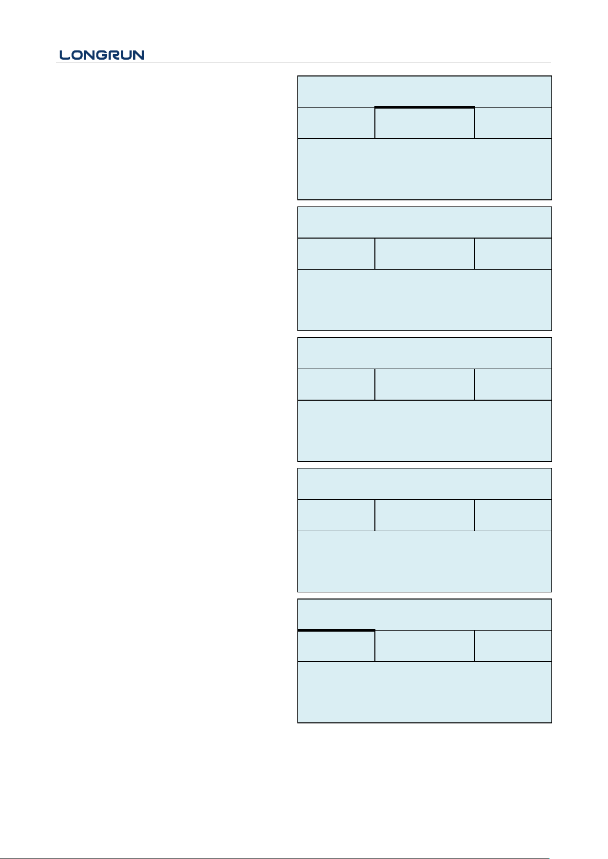
Enter the Upper alarm value, any of the measured
flow, which is higher than the high value, will
activate the alarm in the OCT hardware or relay
output signal.
M36
Ration
Following is the Ration opinions:
a. Key CTRL
b. AI1 CTRL
c. AI2 CTRL
d. Uart CTRL
M37
Micro SD
Following is the opinions for the record.
a. No Energy
b. All
Input the data collection time interval in this menu.
Time is in seconds. The interval can be selected in
the range of 1 ~ 3600 seconds
M40
Toggle Unit
Select the measurement unit as follows:
a. Metric
b. British
M41
Flow Unit
The following flow rate units are available:
0. Cubic Meters (m3)
1. Liters (1)
2. USA Gallons (GAL)
3. Imperial Gallons (Imp gal)
4. Million Gallons (mg)
5. Cubic Feet (cf)
6. USA Barrels (US bbl)
LowerL
0.0
m3/h
UpperL
1000.0
m3/h
M35
Alarm Settings
*R
Alarm1
Alarm2
Option
a.Key CTRL
Value
1000.0
m3/h
M36
Ration
*R
Option
a.No Energy
Cycle
60s
M37
Micro SD
*R
Option
a.Metric
M40
Toggle Unit
*R
Unit
MULT.
M41
Flow Unit
*R
Total
m3
Rate
m3/h
- 35 -
Page 37
LRF-3300S Ultrasonic Transit-time Flow meter
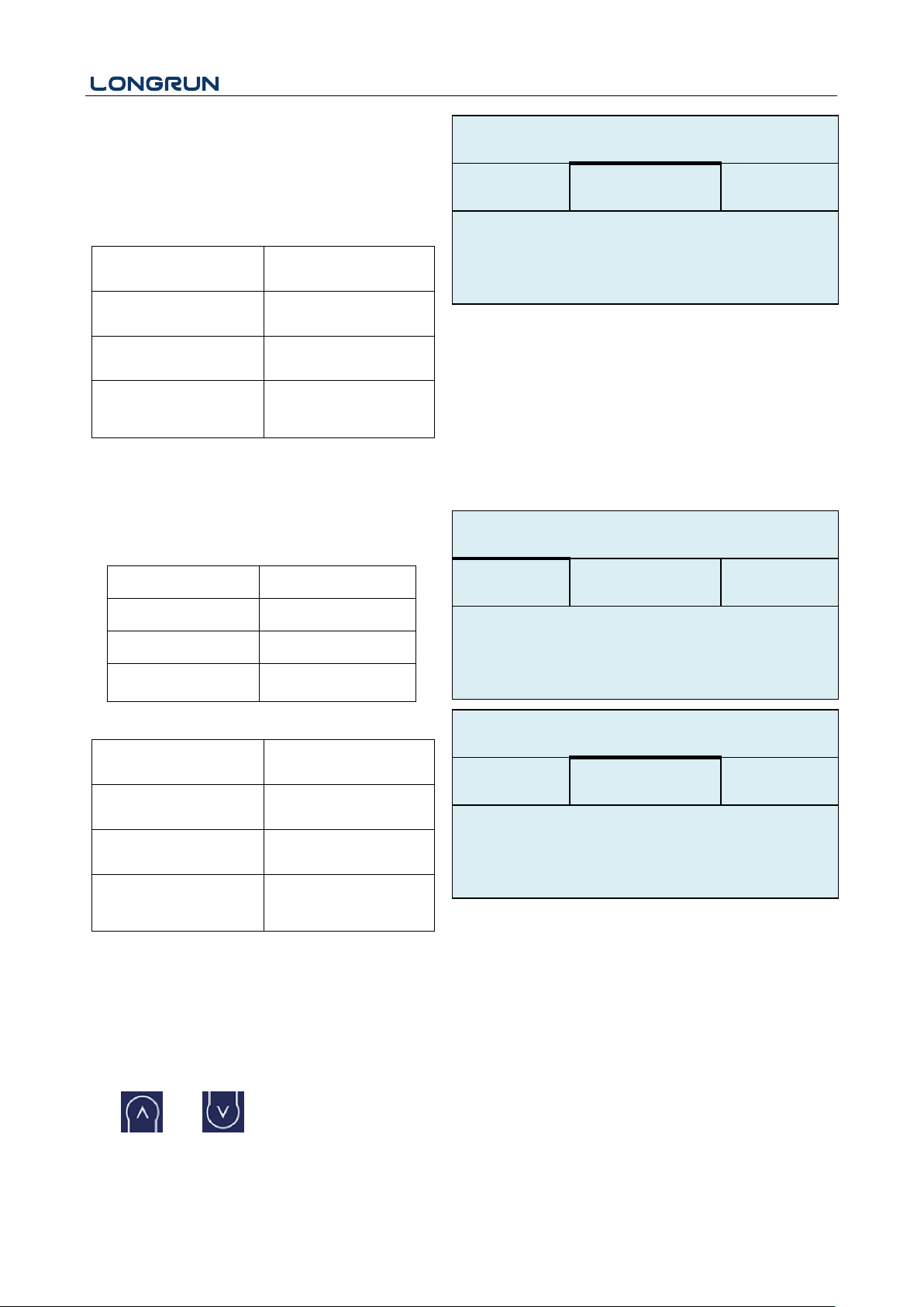
7. Imperial Barrels (Imp bbl)
8. Oil Barrels (Oil bbl)
The following time units are available:
/Day /Hour
/Min /Sec
Factory default is Cubic Meters/hour.
a. x 0.001 (E-3)
b. x 0.01(E-2)
c. x 0.1(E-1)
d. x 1(E+0)
e. x 10(E+1)
f. x 100(E+2)
g. x 1000(E+3)
h. x
10000(E+4)
M42
Energy Unit
The following Energy units are available:
0. Giga Joule (GJ)
1. Kilocalorie (Kc)
2. MBtu
3. KJ
4. Btu
5. KWh
6. MWh
7. TH
a. x 0.001 (E-3)
b. x 0.01(E-2)
c. x 0.1(E-1)
d. x 1(E+0)
e. x 10(E+1)
f. x 100(E+2)
g. x 1000(E+3)
h. x
10000(E+4)
M43
Temperature Unit
a. ℃
b. ℉
Use and to switch.
Unit
MULT.
M41
Flow Unit
*R
Option
d. *1
Unit
MULT.
M42
Energy Unit
*R
Total
GJ
Rate
GJ/h
Unit
MULT.
M42
Energy Unit
*R
Option
d. *1
- 36 -
Page 38

LRF-3300S Ultrasonic Transit-time Flow meter
M50
Serial Number
Display electronic serial number (S/N) of the
instrument. This S/N is the only one assigned to each
flow meter ready to leave the factory. The factory
uses it for files setup and for management by the
user.
M51
Time and Data
Date and time modifications are made in this menu.
M52
Key Tone
Use this menu to “ON”/ “OFF” the key tone.
M53
Initial Menu
This menu is for the initial interface setting.
M54
Option
a. 。C
M43
TEMP Unit
*R
S/N
FT888888
M50
Serial Number
*R
Tme
8:10:20
Date
2017/8/16
M51
Time/Data
*R
Option
0.ON
M52
Key Ton
*R
- 37 -
Page 39
LRF-3300S Ultrasonic Transit-time Flow meter
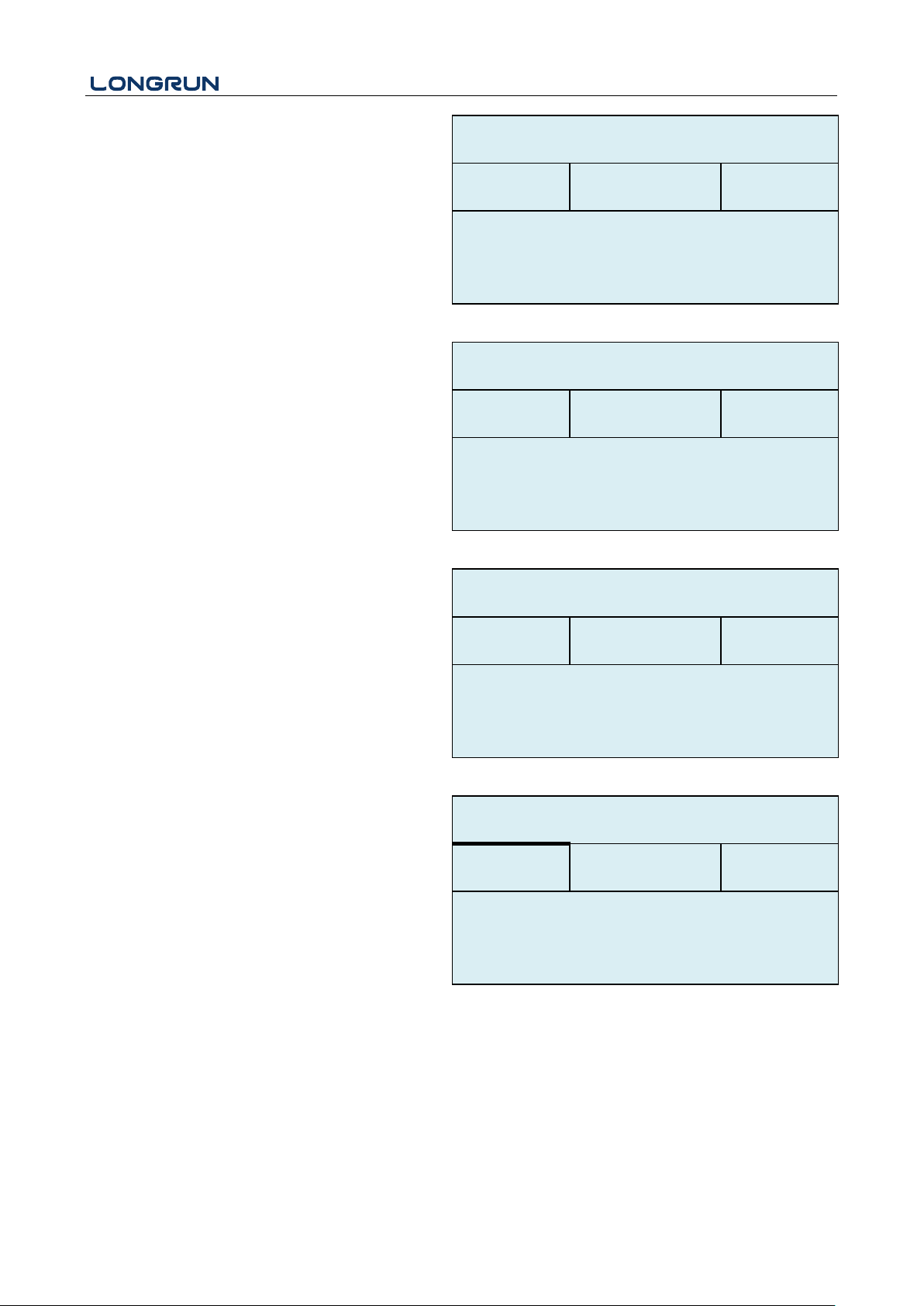
System Lock
Lock the instrument. Once the system is locked, any
modification to the system is prohibited, but the
parameter is readable. Entering your designated
password correctly can be the only way to "Unlock".
The password is composed of 6 numbers. (Please
contact the representative or manufacturer as soon as
possible when the password is lost.)
M55
System Reset
Select 1. Reset to make the instrument back to
factory.
M60
Date Totalizer
The following options are available:
0. Day
1. Month
2. Year
In this window, it is possible to review the historical
flow data net totalizer for any day for the last 31
days, any month for last 12 months and any year for
last 6 years.
M61
Running Time
With this function, it is possible to view the total
Working days since the flow meter left the factory.
M62
CL Adjust
This menu is for the 4-20mA calibration; enter the
pass word to adjust.
Value
M00
M53
Initial Menu
*R
Option
a.Locked
Key
*********
M54
System Lock
*R
Option
0. None
M55
System Reset
*R
Day
Mon
Year
M60
Date Totalizer
*R
Value
08-01
E+0
100.0
m3
- 38 -
Page 40
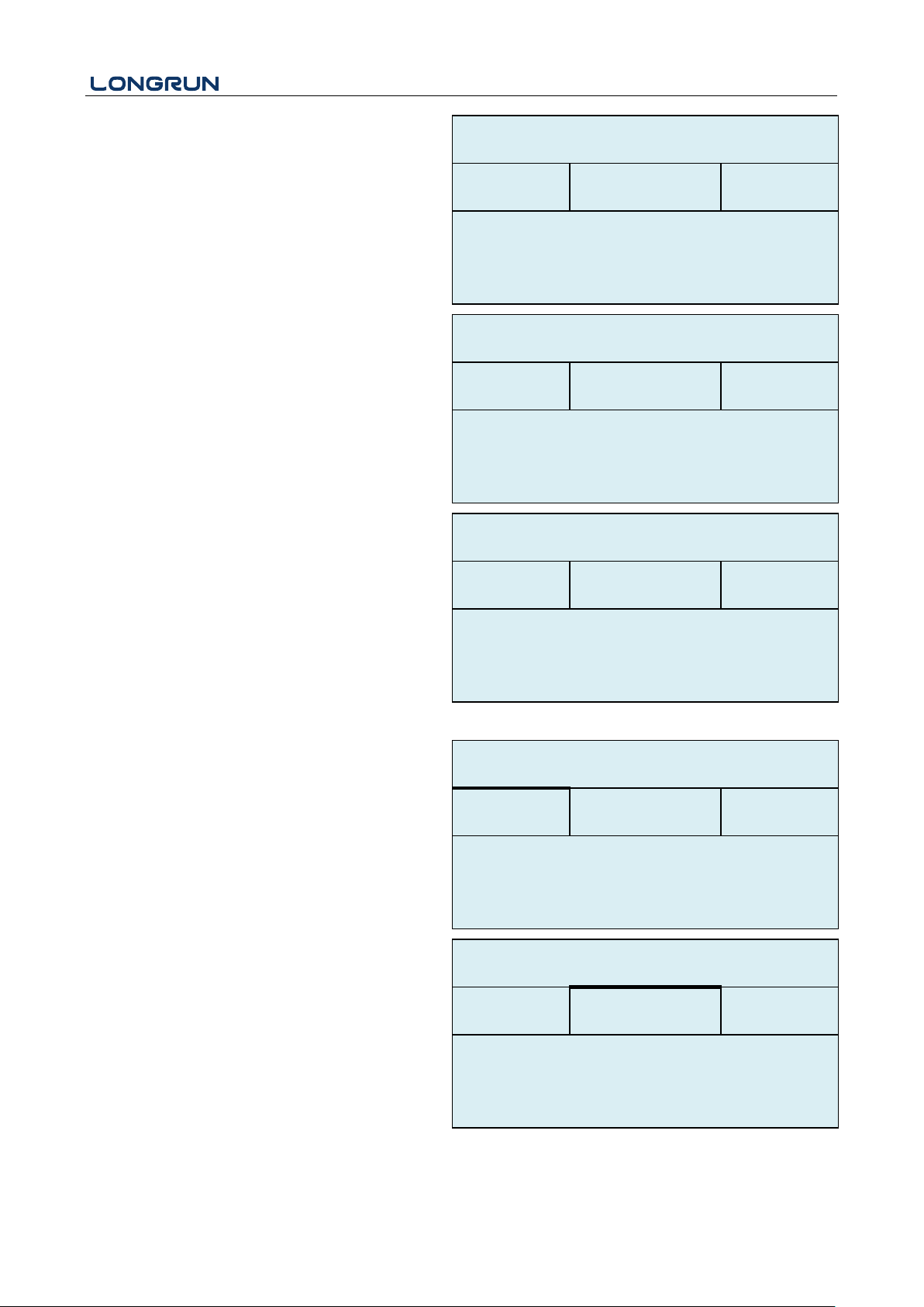
M63
RTD Adjust
This menu is for the RTD calibration; enter the pass
word to adjust.
M64
RTD Adjust
This menu is for the AI calibration; enter the pass
word to adjust.
Value
5
Day
M61
Running Time
*R
4mA
Enter to go
20mA
Enter to go
M62
CL Adjust
*R
0 。C
Enter to go
180。C
Enter to go
M63
RTD Adjust
*R
AI1
AI2
M64
AI adjust
*R
20mA
Enter to go
4mA
Enter to go
AI1
AI2
M64
AI adjust
*R
20mA
Enter to go
4mA
Enter to go
LRF-3300S Ultrasonic Transit-time Flow meter
- 39 -
Page 41
LRF-3300S Ultrasonic Transit-time Flow meter
Codes
The upper right corner
of the screen
Causes
Solutions
*R
System Normal
* System normal.
*E
Signal Not Detected
* Signal not detected.
* Spacing is not correct
between the transducers
or not enough coupling
compound applied to
face of transducers.
* Transducers installed
improperly.
* Scale is too thick.
* New pipe liner.
* Attach transducer to the pipe and
tighten it securely. Apply a plenty
of coupling compound on
transducer and pipe wall.
* Remove any rust, scale, or loose
paint from the pipe surface. Clean it
with a file.
* Check the initial parameter
settings.
* Remove the scale or change the
scaled pipe section. Normally, it
is possible to change a
measurement location. The
instrument may run properly at a
new site with less scale.
* Wait until liners solidified and
saturated.
*D
Adjusting Gain
* Adjusting gain for
normal measurement.
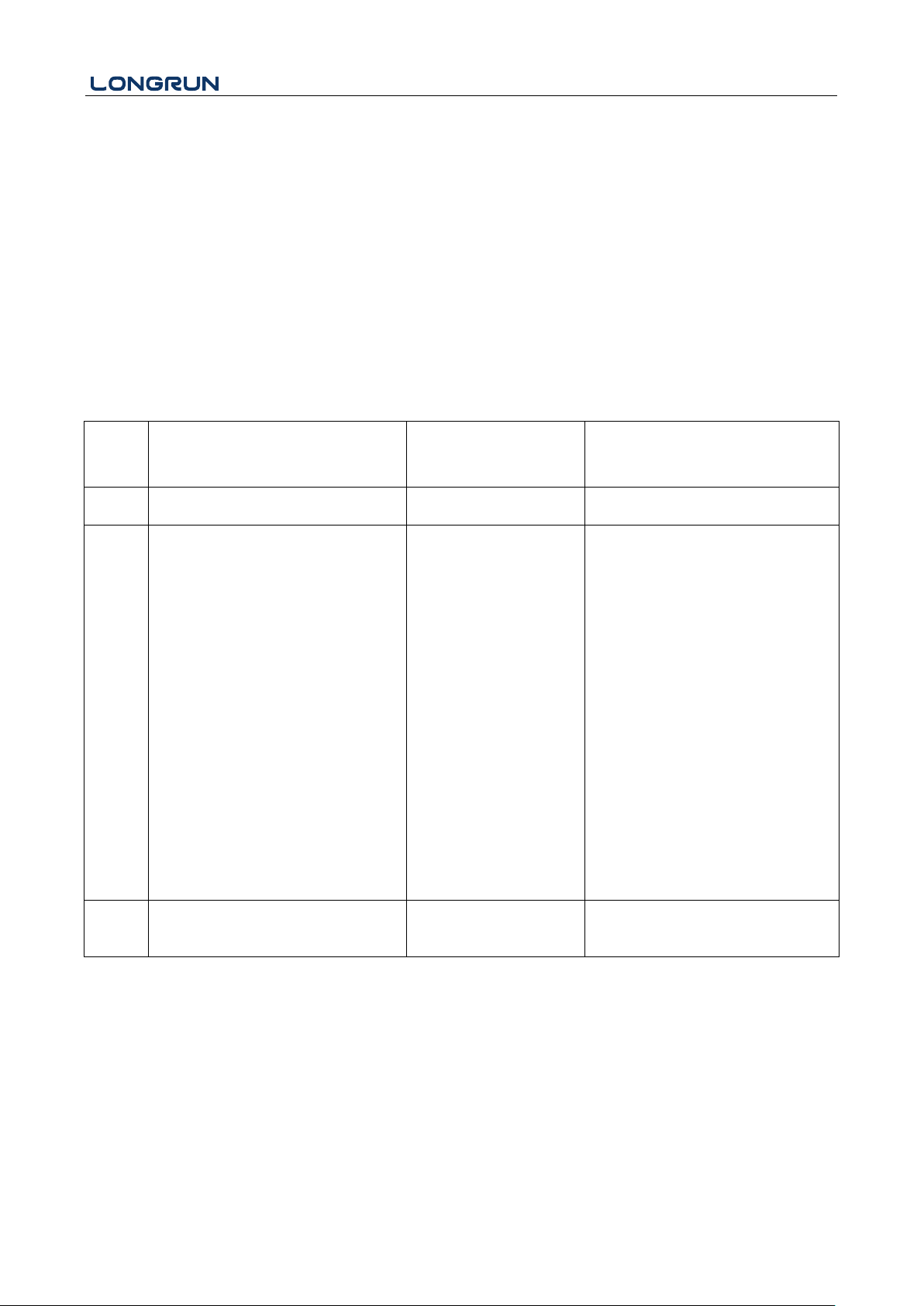
6. Error Diagnoses
The ultrasonic flow meter has advanced self-diagnostics functions and displays any errors in the upper right
corner of the LCD via definite codes in a date/time order. Some errors can be detected during normal operation.
Undetectable errors caused by unskilled operation, incorrect settings and unsuitable measurement conditions can
be displayed accordingly during work. This function helps the user detect the errors and find causes quickly; thus,
problems can be solved in a timely manner according to the solutions listed in the following table.
If a problem still exists, please contact the factory or the factory’s local representative for assistance.
6.1. Table 1. Error Codes and Solutions (during operation)
- 40 -
Page 42

LRF-3300S Ultrasonic Transit-time Flow meter
6.2. Frequently Asked Questions and Answers
Question: New pipe, high quality material, and all installation requirements met: why still no signal detected?
Answer: Check pipe parameter settings, installation method and wiring connections. Confirm if the coupling
compound is applied adequately, the pipe is full of liquid, transducer spacing agrees with the screen
readings and the transducers are installed in the right direction.
Question: Old pipe with heavy scale inside, no signal or poor signal detected: how can it be resolved?
Answer: Check if the pipe is full of fluid. Try the Z method for transducer installation (If the pipe is too close to
a wall, or it is necessary to install the transducers on a vertical or inclined pipe with flow upwards
instead of on a horizontal pipe).
Carefully select a good pipe section and fully clean it, apply a wide band of coupling compound on
each transducer face (bottom) and install the transducer properly.
Slowly and slightly move each transducer with respect to each other around the installation point until
the maximum signal is detected. Be careful that the new installation location is free of scale inside the
pipe and that the pipe is concentric (not distorted) so that the sound waves do not bounce outside of the
proposed area.
For pipe with thick scale inside or outside, try to clean the scale off, if it is accessible from the inside.
(Note: Sometimes this method might not work and sound wave transmission is not possible because of
the a layer of scale between the transducers and pipe inside wall).
Question: Why is the CL output abnormal?
Answer: Check to see if the desired current output mode is set in Window M32-Mode.
Check to see if the maximum and minimum current values are set properly in Windows M32-Range.
Re-calibrate CL and verify it in Window M32-Check.
Question: Why is the flow rate still displayed as zero while there is fluid obviously inside the pipe and a symbol
of "R" displayed on the screen?
Answer: Check to see if "Set Zero" was carried out with fluid flowing inside the pipe (Refer to Window M22).
If it is confirmed, recover the factory default in Window M22-Reset.
- 41 -
Page 43
LRF-3300S Ultrasonic Transit-time Flow meter
downup
TT
TMD
V
2sin
Downstream Transducer
Upstream Transducer
Flow
D
T
down
T
up
7. Product Overview
7.1. Introduction
LRF-3300S is a wall-mount, clamp- on type ultrasonic flow meter which uses the transfer time technology. Clamp
on type ultrasonic flow meter is easy to install and no need to cut off the pipe that saves you lots of troubles and
cost. At the same time LRF-3300S has our unique calculate software to ensure the high accuracy and low velocity
response.
LRF-3300S ultrasonic flow meter widely application in oil industry, water treatment, pure water, chemical and
etc.
LRF-3300S could add the RTD model and temperature sensor become an energy meter to monitoring the energy
use, help to save the energy.
7.2. Features of LRF-3300S
Comparing With other traditional flow meter or ultrasonic flow meter, it has distinctive features such as high
precision, high reliability, high capability and low cost, the Flow meter features other advantages:
1. With ARM COMA chip, low power consumption, high reliability, anti-jamming and outstanding benefits.
2. User-friendly menu designed. Parameters of pipe range, pipe material, pipe wall thickness, output signals, etc
can be conveniently entered via the windows. British and Metric measurement units are available.
3. Daily, monthly and yearly totalized flow: Totalized flow for the last 64 days and months as well as for the
last 6 years are may be viewed. With the SD Card, 512 files can be stored; the time interval can be within 1
second.
4. Parallel operation of positive, negative and net flow totalizer with scale factor and 7 digit display. Internally
configured batch controller makes batch control convenient.
The flow meter ensures the higher resolution and wider measuring range by the 0.04ns high resolution, high
linearity and high stability time measuring circuit and 32 bits digits processing program.
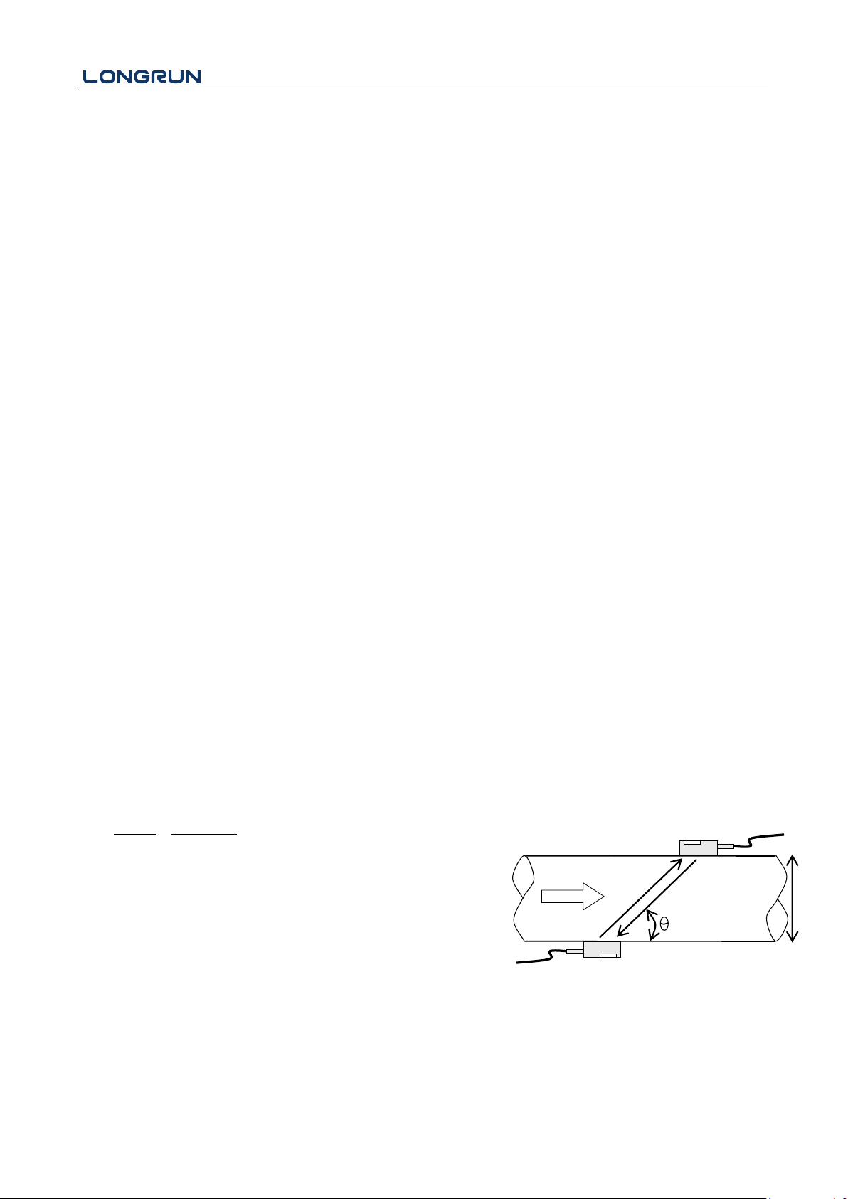
7.3. Theory of Operation
When the ultrasonic signal is transmitted through the flowing liquid, there will be a difference between the
upstream and downstream transit time ( travel time or time of flight ), which is proportional to flow velocity,
according to the formula below.
Remarks:
V Medium Velocity
M Ultrasonic frequency of reflection
D Pipe Diameter
θ The angle between the ultrasonic signal and the flow
Tup Transit time in the forward direction
T
Transit time in the reverse direction
down
ΔT = T
up
– T
down
- 42 -
Page 44
LRF-3300S Ultrasonic Transit-time Flow meter
7.4. Applications
Water, sewage ( with low particle content ) and seawater;
Water supply and drainage water;
Power plants ( nuclear power plant, thermal and hydropower plants ), heat energy, boiler feed water and
energy management system;
Metallurgy and mining applications ( cooling water and acid recovery, for example );
Petroleum and chemicals;
Food, beverage and pharmaceutical;
Marine operation and maintenance;
Energy economy supervision and water conservation management;
Pulp and paper;
Pipeline leak detection;
Regular inspection, tracking and collection;
Energy measuring and balance;
Network monitoring systems and energy / flow computer management.
- 43 -
Page 45
LRF-3300S Ultrasonic Transit-time Flow meter
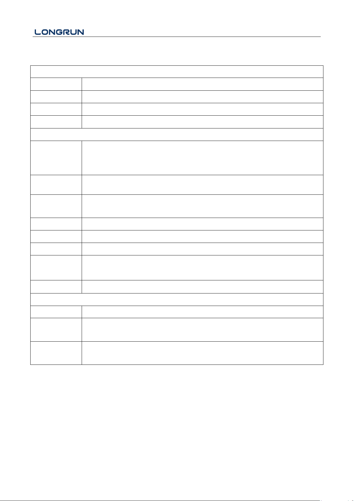
Performance specifications
Flow Rage
0 ft/s ~ ± 40 ft/s ( 0 m/s ~ ± 12 m/s ).
Accuracy
± 0.5% of measured value.
Repeatability
0.1%.
Pipe Size
1″ ~ 200″ ( 25 mm ~ 5000 mm ).
Function Specifications
Output
Analog output: 0/4 ~ 20 mA, ( max load 750 Ω );
Pulse output: 0 ~ 9999 Hz, OCT ( min. and max. frequency is adjustable );
Relay output: max. frequency 1Hz ( 1A@125VAC or 2A@30VDC ).
Communication
Interface
RS232 & RS485.
SD Card
( standard )
Max record: 512 days.
Record time interval: 1 ~ 3600 s.
Power Supply
90 ~ 245 VAC, 48 ~ 63 Hz Or 10 ~ 36 VDC.
Keypad
16 light tactile keys.
Display
256*128 lattice, backlit LCD.
Temperature
Transmitter: -40°F ~ 140 °F (- 40℃ ~ 60℃ ).
Transducer: -40 °F ~ 176 °F ( - 40 ℃ ~ 80 ℃, standard ).
Humidity
Up to 0 ~ 99% RH, non - condensing.
Physical specifications
Transmitter
Die-cast aluminum, IP65.
Transducer
Encapsulated design.
Standard / Maximum cable length: 30 ft / 1000 ft ( 9m / 305 m ).
Weight
Transmitter: approximately 4.7 lb ( 2.15 kg ).
Transducer: approximately 2.0 lb ( 0.9 kg ). ( standard )
7.5. Specifications
- 44 -
Page 46
LRF-3300S Ultrasonic Transit-time Flow meter
Attention
In the communication protocol used functions, RS232 and RS485 serial communications cannot
be used at the same time.
8. Appendix3 – Serial Interface Network Use
and Communications Protocol
8.1. Overview
The flow meter has perfect communication protocol. It can also be connected to a RS-485 Modbus .
Two basic schemes can be chosen for networking, i.e. the analog current output method only using the flow meter
or the RS232 communication method via serial port directly from the flow meter. This method is suitable to
replace dated instruments in old monitoring networks. The later method is used in new monitoring network
systems. It has advantages include low hardware investment and reliable system operation.
When the serial port communications method is directly used to implement a monitoring network system, the
address identification code of the flow meter is used as a network address code. Expanded command set with [W]
is used as communication protocol.
RS-232 (Cable length 0 ~ 15m ) or RS-485 ( cable length 0 ~ 1000m ) can be directly used for data transmission
links for a short distance. Current loop can be used in medium or long distance transmission.
When the flow meter is used in a network environment, various operations can be performed by a host device,
except for programming of the address identification code, which needs to be done via the flow meter keyboard.
The command answer mode is used in data transmission, i.e. the host device issues commands and the flow meter
answers correspondingly.
Common/special flow / thermal data monitoring system developed by our company can be used for flow data
collection. Based on characteristics of the flow meter, the system makes full use of software and hardware designs
with flow meter features. The system is simple, clear, economical, and reliable in operation.
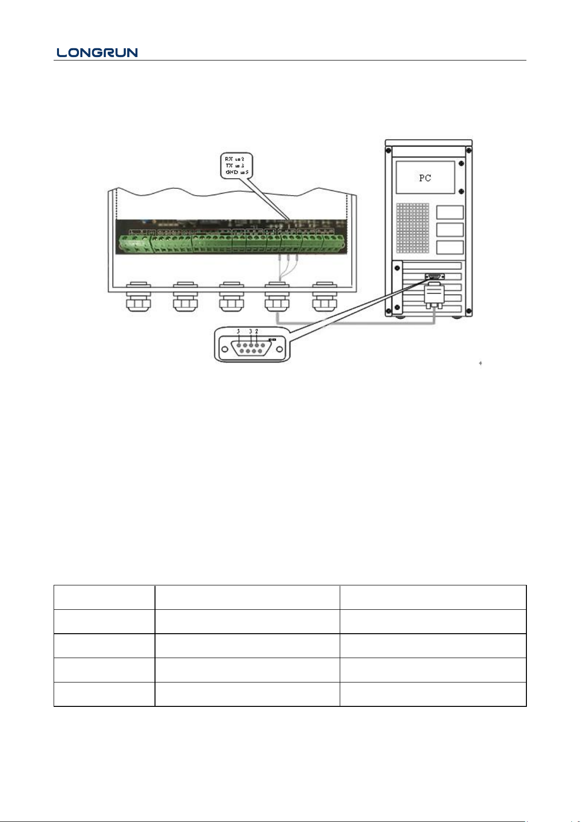
8.2. Serial port definitions
Flow meter - RS232:
TXD send
RXD receive
GND ground
PC:
PIN 1 empty
PIN 2 RXD send
PIN 3 TXD send
PIN 4 ground
PIN 5 ground
PIN 6 empty
PIN 7 empty
PIN 8 empty
PIN9empty
- 45 -
Page 47
LRF-3300S Ultrasonic Transit-time Flow meter
Command
Description
Data format
RFR(cr)(lf)
Return instantaneous flow
±d.ddddddE±dd(cr) Note1
RVV(cr)(lf)
Return instantaneous velocity
±d.ddddddE±dd(cr)
RT+(cr)(lf)
Return positive accumulative flow
±ddddddd.dE±d(cr) Note 2
RT-(cr)(lf)
Return negative accumulative flow
±ddddddd.d±d(cr)
8.3. Direct connection via RS232 to the host device
See the below list of flowmeter serial port definitions.
8.4. Communications protocol and the use
The flow meter supports these three communication protocols: FUJI Protocol, MODBUS-C Protocol, MODBUS-I
Protocol.
8.4.1 HL Protocol
The communication protocol format used by the ultrasonic flow meter is an expanded set of the HL FLV series
flow meter protocol. The host device requests the flow meter to answer by sending a "command". The baud rate of
asynchronous communication (Primary station: computer system; Secondary station: ultrasonic flow meter) is
generally 9600BPS. A single byte data format (10 bits): one start bit, one stop bit and 8 data bits. Check bit: none.
A data character string is used to express basic commands and a carriage return (ENTER) is used to express the
end of a command. The characteristic is that the string of data is flexible. The order applies to both RS232 and
RS485. Frequently used commands are as follows:
Communications commands
- 46 -
Page 48
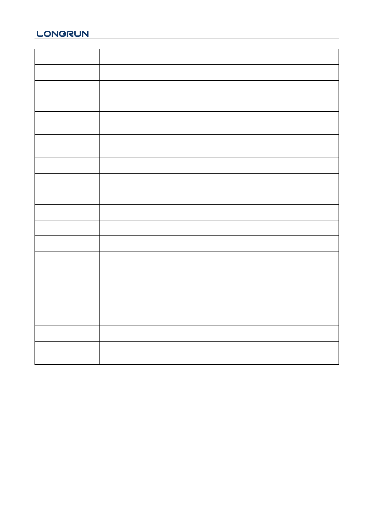
LRF-3300S Ultrasonic Transit-time Flow meter
RTN(cr)(lf)
Return net accumulative flow
±ddddddd.d±d(cr)
RTH(cr)(lf)
Return net accumulative energy(hot)
±ddddddd.d±d(cr)
RT-(cr)(lf)
Return net accumulative energy(cold)
±ddddddd.d±d(cr)
RER(cr)(lf)
Return instantaneous energy value
±d.ddddddE±dd(cr)
RA1(cr)(lf)
Return analog input value of AI1
(Temperature, Pressure, etc.)
±d.ddddddE±dd(cr)
RA2(cr)(lf)
Return analog input value of AI2
(Temperature, Pressure, etc.)
±d.ddddddE±dd(cr)
RID(cr)(lf)
Return Net address of the instrument
ddddd(cr) 5 bits in length
RSS(cr)(lf)
Return signal intensity
UP:dd.d,DN:dd.d,Q=dd(cr)
REC(cr)(lf)
Return current error code
*R/*D/*E Note 3
RRS(cr)(lf)
Return Relay Status
ON/OFF(cr)
RDT(cr)(lf)
Current date and time
yy-mm-dd,hh:mm:ss(cr)
RSN(cr)(lf)
Return serial number
dddddddt(cr) Note 4
SFQdddd.d(cr)(lf)
OCT setting
dddd.d(cr)
Successful setting will back to “OK”
SCLdd.d(cr)(lf)
Current setting
dd.d(cr)
Successful setting will back to “OK”
SRS(cr)(lf)
Start quantitative control
OK(cr)
Successful setting will back to “OK”
P
Prefix of return command with check
Note 5
W
Networking command prefix of numeric
string address
Note 6
Note:
1. (cr)expresses carriage return. Its ASCII value is 0DH. (lf) expresses line feed. Its ASCII value is 0AH.
2. "d" expresses 0-9 number. 0 value is expressed as +0.000000E+00.
3. "d" expresses 0-9 numbers. There is no decimal point in integral part before "E".
4. dddddddd means the serial number of the instrument, t means the model of the instrument.
5. The character P can be added before every basic command. It means that the transferred data has CRC
verification. The method of verification is to add all of the data back to the data, which is cumulative and
binary, and its low 8-bit binary data is taken.
E.g. The return information of the RT(cr)(lf) is :+1234567E+0m3(cr)(lf), (the relative binary system data
is 2BH,31H,32H,33H,34H,35H,36H,37H,45H,2BH,30H,6DH,33H,20H,0DH,
- 47 -
Page 49
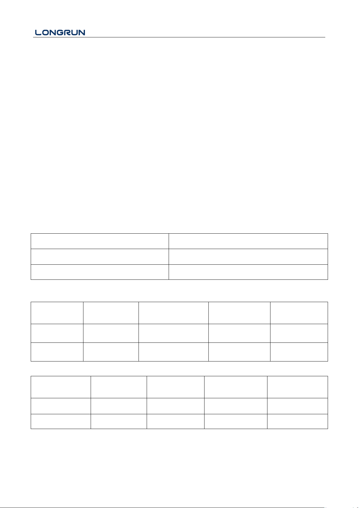
LRF-3300S Ultrasonic Transit-time Flow meter
Function Code
Performance data
0x03
Read register
0x06
Write single register
Slave Address
Operation
Function Code
First Address Register
Register Number
Verify Code
1 byte
1 byte
2 bytes
2 bytes
2 bytes
0x01 ~ 0xF7
0x03
0x0000 ~ 0xFFFF
0x0000 ~ 0x7D
CRC (Verify )
Slave Address
Read Operation
Function Code
Number of Data
Bytes
Data Bytes
Verify Code
1 byte
1 byte
1 byte
N*x2 byte
2 bytes
0x01 ~ 0xF7
0x03
2xN*
N*x2 ( Data )
CRC ( Verify )
0AH) The sum of all of its return data is =2BH+31H+32H+33H+34H+35H+
36H+37H+45H+2BH+30H+6DH+33H+20H=2F7, The low 8-bit data of its binary is F7.
Therefore, the data of the order PRT (cr) (lf) is called + 1234567E + 0m3!F7 (cr) (lf), "!"For delimiters,
the preceding is the character of the summation, followed by a check code of 1 byte.
6. Usage of prefix W: W+ numeric string address code +basic command. Value range of the numeric string is 0
~ 255, except 13 (0DH carriage return ), 10 ( 0AH line feed ). If the instantaneous velocity of No. 123
flow meter is to be accessed, the command W123DV (cr)(lf) can be issued. The corresponding binary
code is 57H, 31H, 32H, 33H, 44H, 56H, 0DH, 0AH, only the same instrument with the same address of
the Internet address and command will send back the data.
7. W and P commands can be used in combination, for example, W123PRT +, which means that the
instrument that reads the network address is the cumulative value of the instrument with 123, and its
return data has eight accumulations and checksums."s" expresses ON or OFF or UD. For example,
"TR:ON, RL:ON" expresses that the OCT and relay are in an actuated status; "TR:UD,RL:UD"
expresses that the OCT and relay are not actuated.
8.4.2. MODBUS-I Communication Protocol
This MODBUS-I Protocol uses RTU transmission mode. The Verification Code uses CRC-16-IBM (polynomial is
X16+X15+X2+1, shield character is 0xA001) which is gained by the cyclic redundancy algorithm method.
MODBUS-I RTU mode uses hexadecimals to transmit data.
1. MODBUS-I Protocol Function Code and Format
The flow meter protocol supports the following two-function codes of the MODBUS:
2. MODBUS Protocol function code 0x03 usage
The host sends out the read register information frame format:
The slave returns the data frame format:
N* = Data register number
3. MODBUS Protocol function code 0x06 usage
- 48 -
Page 50
LRF-3300S Ultrasonic Transit-time Flow meter
Slave Address
Operation
Function Code
Register Address
Register Data
Verify Code
1 byte
1 byte
2 bytes
2 bytes
2 bytes
0x01 ~ 0xF7
0x06
0x0000 ~ 0xFFFF
0x0000 ~ 0xFFFF
CRC ( Verify )
Slave Address
Operation
Function Code
Register Address
Register Data
Verify Code
1 byte
1 byte
2 bytes
2 bytes
2 bytes
0x01 ~ 0xF7
0x06
0x0000 ~ 0xFFFF
0x0000 ~ 0xFFFF
CRC ( Verify )
The host sends a command to write a single register information frame format ( function code 0x06 ):
The slave returns the data frame format ( function code 0x06 ):
The range of flow meter addresses 1 to 247 (Hexadecimal: 0x01 ~ 0xF7 ), and can be checked in the Menu 46.
For example, decimal number "11" displayed on Menu 46 means the address of the flow meter in the MODBUS
protocol is 0x0B.
The CRC Verify Code adopts CRC-16-IBM (polynomial is X16+X15+X2+1, shield character is 0xA001) which is
gained by the cyclic redundancy algorithm method. Low byte of the verify code is at the beginning while the high
byte is at the end.
For example, to read the address 1 (0x01) in the RTU mode, if the instantaneous flow rate uses hour as a unit
(m3/h), namely reads 40005 and 40006 registers data, the read command is as follows:
0x01 0x03 0x00 0x04 0x00 0x02 0x85 0xCA
Flow meter Address Function Code First Address Register Register Numbers CRC Verify Code
Flow meter returned data is (assuming the current flow=1.234567m3/h)
0x01 0x03 0x04 0x06 0x51 0x3F 0x9E 0x3B 0x32
Flow meter Address Function Code Data Bytes Data(1.2345678) CRC Verify Code
The four bytes 3F 9E 06 51 is in the IEEE754 format single precision floating point form of 1.2345678.
Pay attention to the data storage order of the above example. Using C language to explain the data, pointers can be
used directly to input the required data in the corresponding variable address, the low byte will be put at the
beginning, such as the above example 1.2345678 m/s, 3F 9E 06 51 data stored in order as 51 06 9E 3F.
For example, it converts the address 1 (0x01) to 2(0x02)under the RTU mode, so to write the data of flowmeter
44100 register as 0x02, the write command is as follows:
0x01 0x06 0x10 0x03 0x00 0x02 0xFC 0xCB
Flow meter Address Function Code Register Address Register Number CRC Verify Code
Flow meter returned data is:
0x01 0x06 0x10 0x03 0x00 0x02 0xFC 0xCB
Flow meter Address Function Code Register Address Register Number CRC Verify Code
4. Error Check
The flow meter only returns one error code 0x02 which means data first address in error.
- 49 -
Page 51
LRF-3300S Ultrasonic Transit-time Flow meter
PDU
Address
Register
Read
Write
Type
No. registers*
$0000
40001
Flow/s - low word
32 bits real
2
$0001
40002
Flow/s - high word
$0002
40003
Flow/m - low word
32 bits real
2
$0003
40004
Flow/m- high word
$0004
40005
Flow/h - low word
32 bits real
2
$0005
40006
Flow/h - high word
$0006
40007
Velocity – low word
32 bits real
2
$0007
40008
Velocity – high word
$0008
40009
Positive total – low word
32 bits int.
2
$0009
40010
Positive total – high word
$000A
40011
Positive total – exponent
16 bits int. 1
$000B
40012
Negative total – low word
32 bits int.
2
$000C
40013
Negative total – high word
$000D
40014
Negative total – exponent
16 bits int. 1
$000E
40015
Net total – low word
32 bits int. 2
For example, to read address 1 (0x01) of the flowmeter 40002 register data in the RTU mode, the flowmeter
considers it to be invalid data, and sends the following command:
0x01 0x03 0x00 0x01 0x00 0x01 0xD5 0xCA
Flow meter Address Function Code Register Address Register Number CRC Verify Code
Flow meter returned error code is:
0x01 0x83 0x02 0xC0 0xF1
Flow meter Address Error Code Error Extended Code CRC Verify Code
5. MODBUS Register Address List
The flow meter MODBUS Register has a read register and a write single register.
a) Read Register Address List (use 0x03 function code to read)
- 50 -
Page 52
LRF-3300S Ultrasonic Transit-time Flow meter
$000F
40016
Net total – high word
$0010
40017
Net total – exponent
16 bits int. 1
$0011
40018
Energy flow – low word
32 bits int.
2
$0012
40019
Energy flow – high word
$0013
40020
Energy total(hot) –low word
32 bits real
2
$0014
40021
Energy total(hot) –high word
$0015
40022
Energy total(hot) – exponent
16 bits int. 1
$0016
40023
Energy total(cold ) –high word
32 bits real
2
$0017
40024
Energy total(cold ) – exponent
$0018
40025
Energy total(cold ) – exponent
16 bits int.
1
$0019
40026
Up signal int – low word
32 bits real
2
0 ~ 99.9
$001A
40027
Up signal int – high word
$001B
40028
Down signal int – low word
32 bits real
2
0 ~ 99.9
$001C
40029
Down signal int – high word
$001D
40030
Quality
16 bits int.
1
0 ~ 99
$001E
40031
Error code – char 1
String
1
Refer to "Error
Analysis" for
detailed codes
meanings.
$003B
40060
Flow velocity unit –char 1,2
String
2
Only m/s right
now
$003C
40061
Flow velocity unit –char 3,4
$003D
40062
Flow rate unit –char 1,2
String 2 Note 1
$003E
40063
Flow rate unit –char 3,4
$003F
40064
Flow total unit – char 1,2
String 1
$0040
40065
Energy rate unit – char1,2
String 2 Note 2
- 51 -
Page 53
LRF-3300S Ultrasonic Transit-time Flow meter
$0041
40066
Energy rate unit – char 3,4
$0042
40067
Energy total unit – char 1,2
String
1
$0043
40068
Instrument address –low word
32 bits real
2
$0044
40069
Instrument address –high word
$0045
40070
Serial number – char 1,2
String
4
$0046
40071
Serial number – char 3,4
$0047
40072
Serial number – char 5,6
String
4
$0048
40073
Serial number – char 7,8
$0049
40074
Analog Input AI1 Value- low word
32 bits real
2
Returned
temperature value
with RTD option
$004a
40075
Analog Input AI1 Value- high word
$004b
40076
Analog Input AI2 Value- low word
32 bits real
2
$004c
40077
Analog Input AI2 Value- high word
$004d
40078
4-20mA Value- low word
32 bits real
2
Unit: mA
$004e
40079
4-20mA Value- high word
PDU Address
Register
Description
Read/W
rite
Type
No. registers*
$1003
44100
Flow meter address ( 1 - 255 )
R/W
16 bits int.
1
$1004
44101
Communication Baud Rate 0 =
2400,1 = 4800, 2 = 9600, 3 =
19200, 4 = 38400,5 = 56000
R/W
16 bits int.
1
b) Single Write Register Address List ( use 0x06 performance code to write )
Notes:
1. The following flow rate units are available:
0. "m3" -Cubic Meter
1. "l" -Liters
2. "ga" -Gallons
3. "ig" -Imperial Gallons
- 52 -
Page 54
LRF-3300S Ultrasonic Transit-time Flow meter
4. "mg" -Million Gallons
5. "cf" -Cubic Feet
6. "ba" -US Barrels
7. "ib" -Imperial Barrels
8. "ob" -Oil Barrels
2. The following energy units are available:
0. "GJ" -Giga Joule
1. "Kc" -Kilocalorie
2. "MB" -MBtu
3. "KJ" -Kilojoule
4. "Bt" -Btu
5. "Ts" -US Tonnes
6. "Tn" -US Tons
7. "kw" -Kwh
3. 16 bits int—short integer, 32 bits int – long integer, 32 bits real—floating point number,
String—alphabetic string
- 53 -
Page 55
LRF-3300S Ultrasonic Transit-time Flow meter
Fluid
Sound
Velocity (m/s)
Viscosity
water 20℃
1482
1.0
water 50℃
1543
0.55
water 75℃
1554
0.39
water100℃
1543
0.29
water125℃
1511
0.25
water150℃
1466
0.21
water175℃
1401
0.18
water200℃
1333
0.15
water225℃
1249
0.14
water250℃
1156
0.12
Acetone
1190
Carbinol
1121
Ethanol
1168
Alcohol
1440
1.5
Glycol
1620
Glycerin
1923
1180
Gasoline
1250
0.80
Benzene
1330
Toluene
1170
0.69
Kerosene
1420
2.3
Petroleum
1290
Retinal
1280
Aviation
kerosene
1298
Peanut oil
1472
Castor oil
1502
9. Appendix6 - Flow Application Data
9.1. Sound Velocity and Viscosity for Fluids Commonly Used
- 54 -
Page 56
LRF-3300S Ultrasonic Transit-time Flow meter
Pipe Material
Sound Velocity (m/s)
Steel
3206
ABS
2286
Aluminum
3048
Brass
2270
Cast iron
2460
Bronze
2270
Fiber glass-epoxy
3430
Glass
3276
Polyethylene
1950
PVC
2540
Liner Material
Sound Velocity
Teflon
1225
Titanium
3150
Cement
4190
Bitumen
2540
Porcelain enamel
2540
Glass
5970
Plastic
2280
Polyethylene
1600
PTFE
1450
Rubber
1600
9.2. Sound Velocity for Various Materials Commonly Used
- 55 -
Page 57
LRF-3300S Ultrasonic Transit-time Flow meter
t(℃)
v(m/s)
t(℃)
v(m/s)
t(℃)
v(m/s)
0
1402.3
34
1517.7
68
1554.3
1
1407.3
35
1519.7
69
1554.5
2
1412.2
36
1521.7
70
1554.7
3
1416.9
37
1523.5
71
1554.9
4
1421.6
38
1525.3
72
1555.0
5
1426.1
39
1527.1
73
1555.0
6
1430.5
40
1528.8
74
1555.1
7
1434.8
41
1530.4
75
1555.1
8
1439.1
42
1532.0
76
1555.0
9
1443.2
43
1533.5
77
1554.9
10
1447.2
44
1534.9
78
1554.8
11
1451.1
45
1536.3
79
1554.6
12
1454.9
46
1537.7
80
1554.4
13
1458.7
47
1538.9
81
1554.2
14
1462.3
48
1540.2
82
1553.9
15
1465.8
49
1541.3
83
1553.6
16
1469.3
50
1542.5
84
1553.2
17
1472.7
51
1543.5
85
1552.8
18
1476.0
52
1544.6
86
1552.4
19
1479.1
53
1545.5
87
1552.0
20
1482.3
54
1546.4
88
1551.5
21
1485.3
55
1547.3
89
1551.0
22
1488.2
56
1548.1
90
1550.4
23
1491.1
57
1548.9
91
1549.8
24
1493.9
58
1549.6
92
1549.2
25
1496.6
59
1550.3
93
1548.5
26
1499.2
60
1550.9
94
1547.5
27
1501.8
61
1551.5
95
1547.1
28
1504.3
62
1552.0
96
1546.3
29
1506.7
63
1552.5
97
1545.6
30
1509.0
64
1553.0
98
1544.7
31
1511.3
65
1553.4
99
1543.9
32
1513.5
66
1553.7
33
1515.7
67
1554.0
9.3. Sound Velocity in Water (1 atm) at different temperatures
Refer to the sound velocity of other fluids and materials, please contact the factory.
- 56 -
Page 58

LRF-3300S Ultrasonic Transit-time Flow meter
- 57 -
 Loading...