

Page 1
T: 07752 929 363 E: [email protected] W: www.longridge.co.uk
!
Cutting a Mount with the Maxi System
Have some fun with those fabulous panoramics with the Maxi System
The Maxi provides the same service as the Signature but on a larger scale
Instructions for use are the same as for the Signature System
Use both parallelograms in tandem for large mounts but only the
parallelogram nearest to you for smaller sizes.
Cutting a Mount using the Signature System Procedure
Page 2
T: 07752 929 363 E: [email protected] W: www.longridge.co.uk
!
Handy tips:
1. Put your system on a strong, firm work surface. (A bendy table may
result in a curved cut).
2. Make sure it’s at a comfortable working height.
3. Place the System perpendicular to you – not across you.
4. Your position should be slightly to one side of the System so as to allow
your arm to move smoothly with the cutting motion. (R-handers stand
to the L, LH to the R).
5. Work on the back of the mountboard at all times.
6. Remember to rotate the mountboard around for each cut so that the
bevels are not inverted.
7. If the mount is to be fixed flat to the wall make the border the same
width all around. However, if the picture is to be hung with a hook, it will
tilt slightly, creating an illusion of a shorter looking bottom border. To
overcome this, increase the bottom border width a little. This is a
dropped border mount.
Cutting the Exterior
The Straight Cutter is used to cut sheet mountboard down to size, in
preparation for the window aperture.
1. Take out the Cutter Stops.
2. Turn the Guide Rail over and remove the Mount Stop by slackening the
screw with the screwdriver and unlocking the cam.
3. Replace the Guide Rail and set the parallel bar to maximum.
Page 3
T: 07752 929 363 E: [email protected] W: www.longridge.co.uk
!
4. Slide the sheet of mountboard, colour-side down, under the Guide Rail
Unit and up to the Squaring Pins.
5. Mark up the correct size using the tape measure and pencil.
6. Remove the Safety Guard and hook the Straight Cutter onto the Guide
Rail.
7. Push away from you in one smooth and positive action.
The blade is very sharp so always remember to replace the Safety Guard!
Nb. The groove in the Base is only for use with the Straight Cutter – not the
Bevel Cutter.
Cutting the Bevel Window Aperture
The Bevel Cutter is used to produce the window aperture with pleasing
angled cuts - the feature of quality picture mounts.
1. Insert the Mount Stop into the back of the Guide Rail taking into
account the size of the mount. Make sure it does not interfere with the
the parallel bar.
2. Place the Guide Rail onto the Base.
3. Mark up your mount using either of the two scales: the short scale or
the long scale.
Page 4
T: 07752 929 363 E: [email protected] W: www.longridge.co.uk
!
Using the short scale: for borders up to 70mm
• Slide the SprintMat under the Guide Rail Unit and up to the Squaring Pins.
• Slacken the central knob.
• Line up the white indicator line with the measurement required on the
short scale.
• Lock the knob.
• Insert the mount, colour-side down, under the Guide Rail (but on top of
the SprintMat) across to the leading edge of the parallel bar.
• Draw the border line using a 4H pencil against the Guide Rail. Repeat this
for the other three sides.
Using the long scale: for borders up to 130mm
• Slide the SprintMat under the Guide Rail
to the leading edge of the parallel bar
and up to the Squaring Pins.
The SprintMat now operates as a spacer
as well as a cutting medium.
• Slacken the central knob.
• Line up the black indicator line with the measurement required on the
long scale.
• Lock the knob.
Page 5
T: 07752 929 363 E: [email protected] W: www.longridge.co.uk
!
• Insert the mount, colour-side down, under the Guide Rail (on top of the
SprintMat) but this time slide it right across to the back of the parallel
bar.
• Mark out the borders as before.
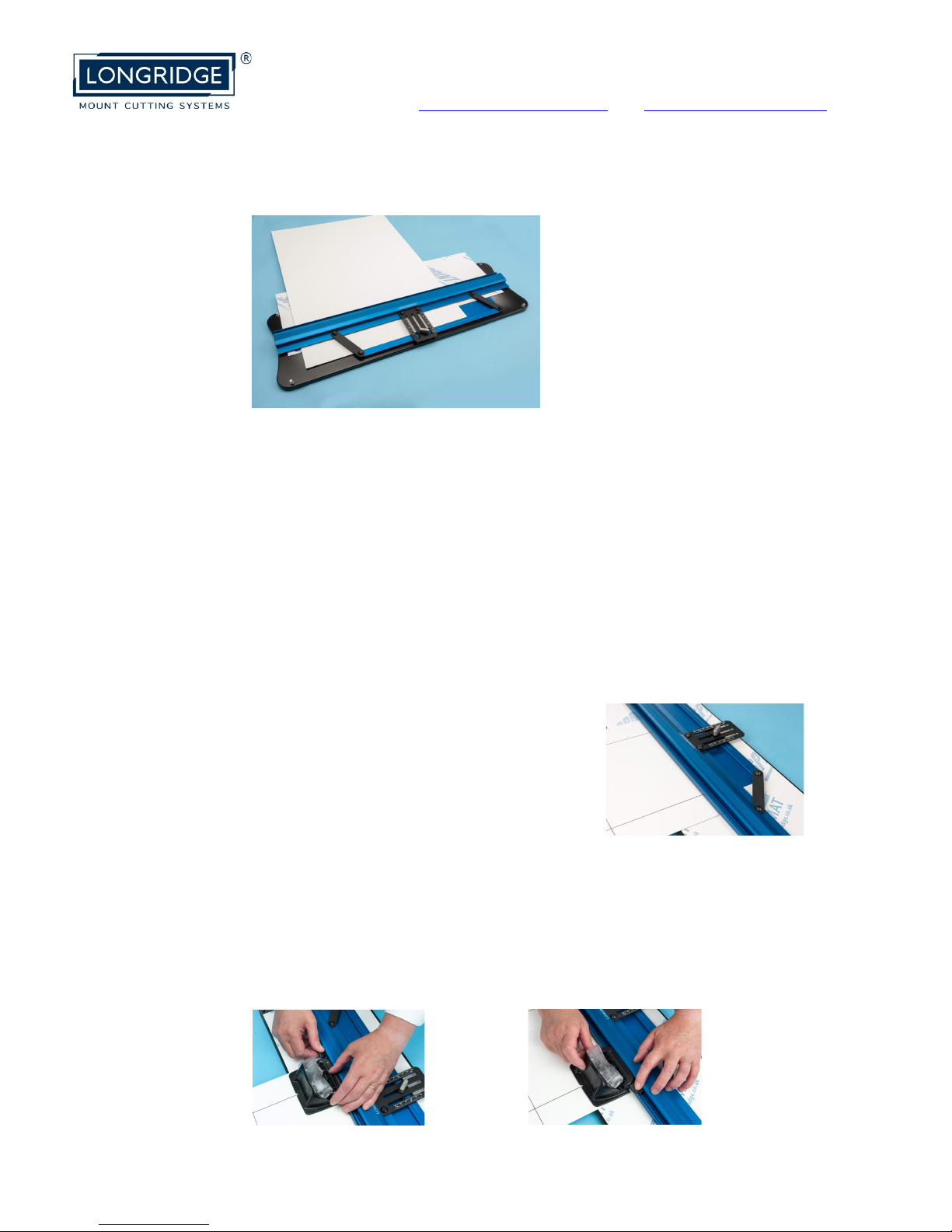
5. Insert the mount back under the Guide Rail, to the parallel bar and up
to the mount stop.
For larger mounts remove the Mount Stop and slide the mount blank up to the
squaring pin instead.
6. Line up the pencil line with the Guide Rail.
7. Place the bevel cutter onto the Guide Rail and insert the two Cutter
Stops.
8. Before cutting: line up the centre of the V on the bevel cutter with the
finish line, draw one cutter stop to the cutter and lock it in position; slide
the cutter back and line up the centre of the V with the start line, draw
the second stop to the cutter and lock it in position.
Page 6
T: 07752 929 363 E: [email protected] W: www.longridge.co.uk
!
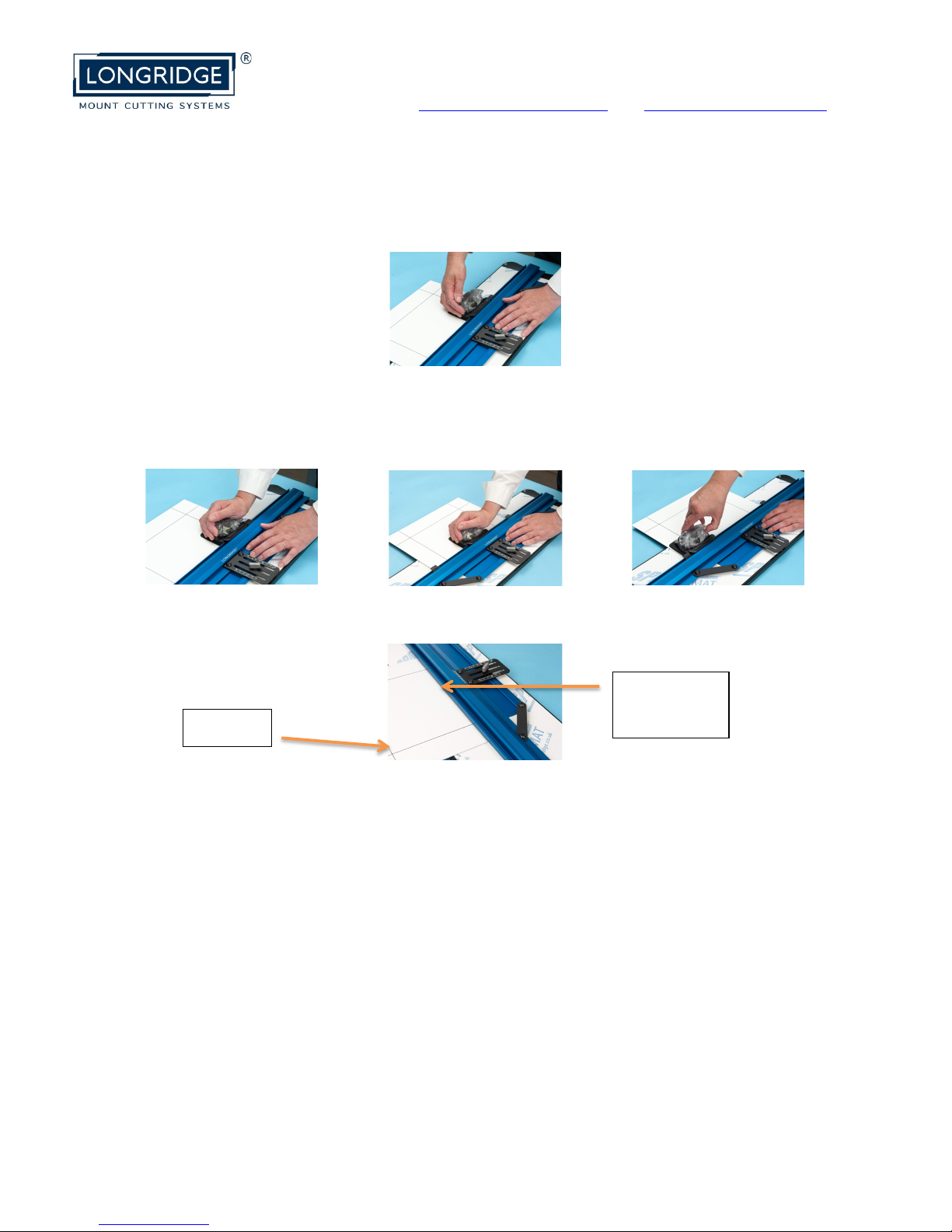
9. Place one hand on the Guide Rail for your support.
10. With the other hand, place the palm of your hand over the clear
carrier, keeping the cutter held firmly up against the bottom stop.
11. Use the heel of the hand to insert the blade fully into the mountboard.
12. Push the cutter along to the other stop in one continuous action.
13. Retract the blade fully and take the cutter off the Guide Rail.
14. Turn the mount around and repeat the steps above.
The cutter stops remain set for the other three sides of a square and for the
opposite long side of a rectangle.
15. If cutting a rectangular mount, reset the stops and repeat the steps
above for each cut.
In just a few minutes you will have produced that desired professional quality
mount that transforms your fabulous image into a wondrous masterpiece!
Extra Information:
1. To cut several same size mounts with the same borders, mark up a master
copy as a template – do not cut the window aperture. The template is then
used to set up the system without the need for any pencil lines.
Longridge Mountcutters are different – anything else is a compromise
Cut line
Next line
to cut
 Loading...