

Page 1

Operating Manual
for
416D/518D/520D
Multi-Purpose
Welding Machines
Page 2

Page 3

160/200/160P/200P AC/DC Series Machine
Table of Contents
Table of Content Pg. 1
Thank you From LONGEVITY Pg. 2
Warranty/Shipping Damage/Order Information Pg. 2-4
Safety Information Pg. 5-6
General Description Pg. 7
Specifications and Ratings Pg. 8-9
What’s Included? Pg. 10
Installation, Wiring, and Setup Instructions Pg. 11-14
Main Unit Knob/Button/Function Diagram Pg. 15
Plasma Cutter Section: Torch Assembly Pg. 16-17
Air Regulator Assembly Pg. 18
Plasma Cutter Operation Tips and Advice Pg. 19-24
TIG Section: Torch Assembly Pg. 25
Selecting the Right Tungsten Pg. 26-27
Selecting the Right Filler Rods Pg. 28
Argon Regulator Installation Pg. 29
Basic TIG Operation Pg. 30-33
Basic Stick/Arc Welding Operation Pg. 34-38
Routine Maintenance Pg. 39
Troubleshooting Pg. 40-41
www.longevity-inc.com 1
Page 4

160/200/160P/200P AC/DC Series Machine
THANK YOU!
We, at LONGEVITY, want to thank you for purchasing our product. You are almost ready to experience
Longevity Welding first hand. Longevity definitely appreciates your business and understand that this
equipment may be overwhelming to setup and operate so we have prepared a manual that will assist you in
understand your new plasma cutter/welder. If you have any questions during or after reading this manual, please
feel to contact us! Please take a moment to register your product on our website at www.longevity-inc.com or
www.lweld.com
Once again, thank you for choosing Longevity as your main welding supplier!
Longevity Global, Inc
23591 Foley St
Hayward, CA 94545
Toll-Free Customer Support: 1-877-LONG-INC / 1-877-566-4462
Website: www.longevity-inc.com
Sales: [email protected]
Customer Service: [email protected]
Dealers: [email protected]
Complaints: [email protected]
Please join our welding forums to share welding tips and tricks, to receive useful information from customers
who also use our products, and to be a part of the Longevity™ welding community at
www.freeweldingforum.com
www.longevity-inc.com
Page 5

160/200/160P/200P AC/DC Series Machine
W
arranty
A manufacturer's limited warranty covers parts only, unless indicated below, and is furnished for five years
from the date of purchase warranting the product to be free of material defect or workmanship as follows:
Plasma Cutters, Welders, and Multi-Purpose Welders (Coverage for Parts and Labor for five years from the
purchase date at our facility).
In the event of product failure or malfunction, the purchaser/recipient must contact LONGEVITY™ GLOBAL,
INC. to obtain an RMA (return or missing) number and a location of a designated repair facility. The welder,
plasma cutter, multi-purpose unit, or any other welding related equipment comes with warranty on all internal
components. The torch, cables, power cord, clamps, air regulator, argon regulator, hoses, case, paint, and
consumables are not covered under warranty. Packages that are not pre-approved for return, and that do not
have an RMA number will be refused and returned to the purchaser/recipient at the purchasers/recipients own
cost. The product must be returned in its original packaging, with all accompanying components. Repair or
replacement of the defective product will be at our option. The repaired/replaced product will then be returned
to the purchaser. LONGEVITY Global, Inc. will cover the return and replacement shipping charges (both ways)
for units in need of warranty within and only for the first 30 days from the purchase date. After the 30 days
from the purchase date, the purchaser shall be responsible for all shipping and handling costs of returning (both
ways) the defective/faulty products for repair or replacement. We are not responsible for lost returns. The labor
coverage only applies if the unit is serviced at our facility or one of our authorized dealers. We will not
reimburse the labor if your wish to have a third-party or unauthorized repair technicians work on the product.
Shipping Damage
Your machine is insured against damage during shipping. Keep all packing materials and containers in case
machine must be returned. We will initiate a claim with the shipping company to cover damage or loss. If there
is shipping damage upon opening your package, our customer service team will work with you to get the matter
resolved.
www.longevity-inc.com 3
Page 6

160/200/160P/200P AC/DC Series Machine
In Warranty Service
Customers, who own machines that are in warranty and require service, should contact our Warranty
Department by email at [email protected] to obtain a return authorization code. In addition to the
warranty we offer, we would like for you to register your product on our website at www.longevity-
inc.com/resources. Remember, warranty starts from the date of purchase. For your convenience, write your
order information below so you can track your order in case you need warranty work.
Order No.: _________________________________
Date of Purchase: _____________________________
Warranty Period: ______________________________
Out-of-Warranty Service
Customers, who own machines that are out of warranty and require service, should contact us for an estimate.
Longevity offers an exchange program on out of warranty units. We also help non LONGEVITY customers
with repairs, replacement, and service.
If your unit is not manufactured by Longevity and you cannot receive service from your manufacturer or seller,
Longevity will lend out hand. Our warranty policy is also available for all plasma cutters and welders. For more
information, please email us at [email protected]
www.longevity-inc.com
Page 7

160/200/160P/200P AC/DC Series Machine
Warnings and Safety
Welding and plasma cutting may be dangerous to the operator and to bystanders, if the
equipment is not operated properly. Welding or cutting must be performed in accordance
with all relevant safety regulations. Carefully read and understand this instruction manual
before installing and operating this equipment.
Changing function modes during welding may damage
equipment.
Before welding, disconnect the electrode-holder cable
from the equipment.
A circuit breaker is required to prevent electrical
overload of the equipment.
Only high quality welding tools should be used.
Electric Shock can be fatal.
Ensure that ground cable is connected in accordance with
applicable safety codes.
Never touch electrodes, wires, or circuit components with
bare hands. Wear dry welding gloves when welding.
The operator must be insulated from the work piece.
Smoke and gas can be harmful to health.
Ensure that the working area is well ventilated.
Avoid breathing smoke and gas generated during the
welding process. Cutting and welding can cause cancer
because of the smoke that comes from the welds and cuts.
Arc-light emission can be harmful to eyes and skin.
Always wear a welding helmet, anti-radiation glass, and
work clothes while welding.
Ensure that people in or near the working area are
protected.
Welding splash is a fire hazard.
Keep flammable material away from the work place.
Keep a fire extinguisher nearby, and have all personnel
trained in it’s use.
Surface noise generated while welding or cutting can be
harmful to hearing.
In the event of a machine fault.
Refer to this instruction manual.
If the fault cannot be determined, contact your local
dealer or supplier for assistance.
www.longevity-inc.com 5
Page 8

160/200/160P/200P AC/DC Series Machine
Safety Tips
Consider the following tips to ensure safe operation of your welding/cutting equipment:
Ensure that this welding equipment is installed in an area free of corrosive chemical gases, flammable gases
or materials, and explosive chemicals.
The area should contain little dust, and have a humidity of no more than 80%.
Operate the welding equipment in an area sheltered from direct sunlight and precipitation. Work area
temperature should be maintained at -10C to +40C;
If, because of an overload, the machine suddenly stops, and it is necessary to restart it, leave the internal fan
operating to lower the inside temperature.
Always wear protective clothing and a welding mask to protect your skin.
Wear safety goggles designed to darken the arc generated by your machine.
Wear suitable noise protection to protect your hearing.
Ensure that machine is grounded through the power cord or on the machine case.
Never operate the machine in bare feet or on a wet floor.
Never switch the machine off while it’s in use. Doing so will damage the internal circuitry.
Ensure that your circuit breaker is rated to handle the current requirements of your machine.
Use a UL approved receptacles and plugs with your machine. Never hard wire the machine to main power.
Work in a well ventilated area to avoid smoke. Keep your head out of the smoke. Ensure that air is flowing
away from you to avoid inhaling smoke.
Use a screen or curtain designed to keep passers by from viewing the arc.
The arc spray and metal spray from machine use may cause nearby fires. Use caution.
Ensure proper ventilation through the machine’s louvers. Maintain a distance of at
between this cutting equipment and any other objects in the work area.
If, after reviewing this manual, you have any problems in setting up or operating your machine, contact us at
[email protected].
least 12 inches
www.longevity-inc.com
Page 9

160/200/160P/200P AC/DC Series Machine
General Description
This WeldMax™ series welding machine, designed for welding low-carbon steel, alloy steel, and stainless steel,
uses advanced inverter technology, which allows us manufacture a unit that can also employ a Plasma Cutter.
By employing high-power MOSFETS and PWM technology, it converts DC voltage to high frequency AC
voltage. Subsequently, voltage is transformed and rectified, resulting in a small main transformer and a lightweight inverter welder, which increases welding performance rates by 30%. High frequency oscillation,
enabling high frequency DC output, is used in the arc-starting system. This machine provides stable output, and
reliable, completely portable, efficient, and low noise generation, while welding or cutting.
The WeldMax™ series has three different functions: TIG, Arc, and plasma cutting. During ARC or TIG welding,
this equipment provides stable output with no arc-length variations. During plasma cutting, the arc, being driven
by highly compressed air, sees a rapid temperature rise up to 10,000 to 15,000 degrees, and becomes highly
ionized. Consequently, it produces the powerful plasma arc for cutting. Plasma cutting saves energy, is efficient,
and creates smooth, high-speed cuts. These machines weld and cut carbon steel, stainless steel, alloy steel, as well
as copper and other nonferrous metals. They are small, highly efficient, energy saving, stable in output, and
reliable. Their ratio of input voltage to output voltage approaches 85 percent.
www.longevity-inc.com 7
Page 10
160/200/160P/200P AC/DC Series Machine
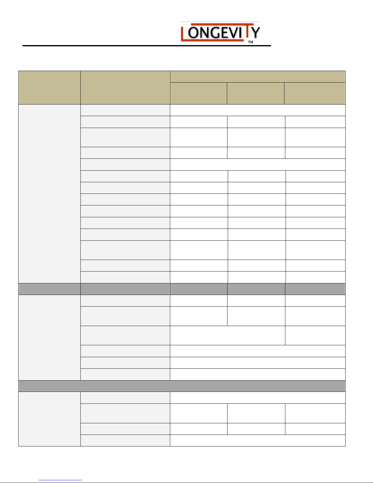
Techinical Specifications and Ratings
MODE
416/518/520D
Units
Parameter
Power Voltage AC110/220v
Input Frequency 50/60 Hz 50/60 Hz 50/60 Hz
Rated Input Current
Power Capacity 4.8KVA 5.0KVA 5.0KVA
No load Voltage 80v/200v
Working Voltage 26.4V 28.1V 29.0V
Efficiency% >80% >80% >80%
Power Factor 0.93 0.93 0.93
Insulation Class F F F
Protection Class IP21S IP21S IP21S
Weight 38lbs 38lbs 39lbs
Size
WeldMax® 416D WeldMax® 518D WeldMax® 520D
20A 110v/50A
220v
18.9 X 9.4 X 13.0
in.
Type
20A
110v/50A220v
19.4 X 13.0 X
12.6 in.
20A 110v/50A
220v
22.0 X 14.4 X 14.0
in.
DC TIG (GTAW)
DC ARC/STICK
Welding Thickness (Steel) .31 in. .39 in. .5 in.
Cutting Thickness (Steel) Up to .5 in. Up to .79 in. Up to .79 in.
Base Current Adjusting Range 5 – 160A 5 - 200A 10 - 200A
Pulse Current Adjusting
Range
Rated Duty Cycle at Max
Amps
Current Down-Slope Time 0-10 Seconds
Remote Control/Pedal Yes
Arc Starting Mode High Frequency
No Load Voltage 60 – 80V
Base Current Adjusting Range
(Amps)
Rated Output Current (Amps) 160A 160A 160A
Rated Duty Cycle at Max
5 – 160A 5 - 200A 10 - 200A
60% 60%
10 – 160A 10 – 160A 10 – 160A
60%
www.longevity-inc.com
Page 11
160/200/160P/200P AC/DC Series Machine
Amps
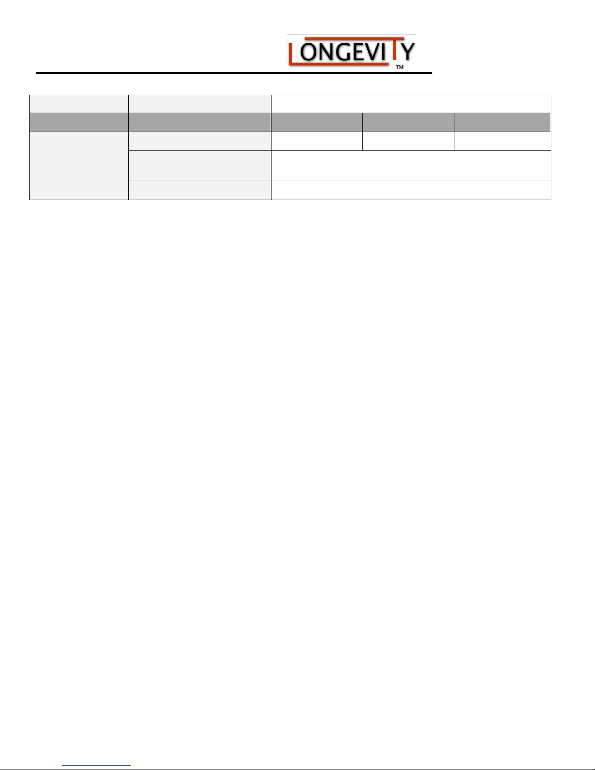
PLASMA
CUTTER
Base Current Range (Amps) 20 – 40A 20 – 50A 20 – 50A
Rated Duty Cycle at Max
Amps
Arc Starting Method High Frequency
60%
www.longevity-inc.com 9
Page 12
160/200/160P/200P AC/DC Series Machine
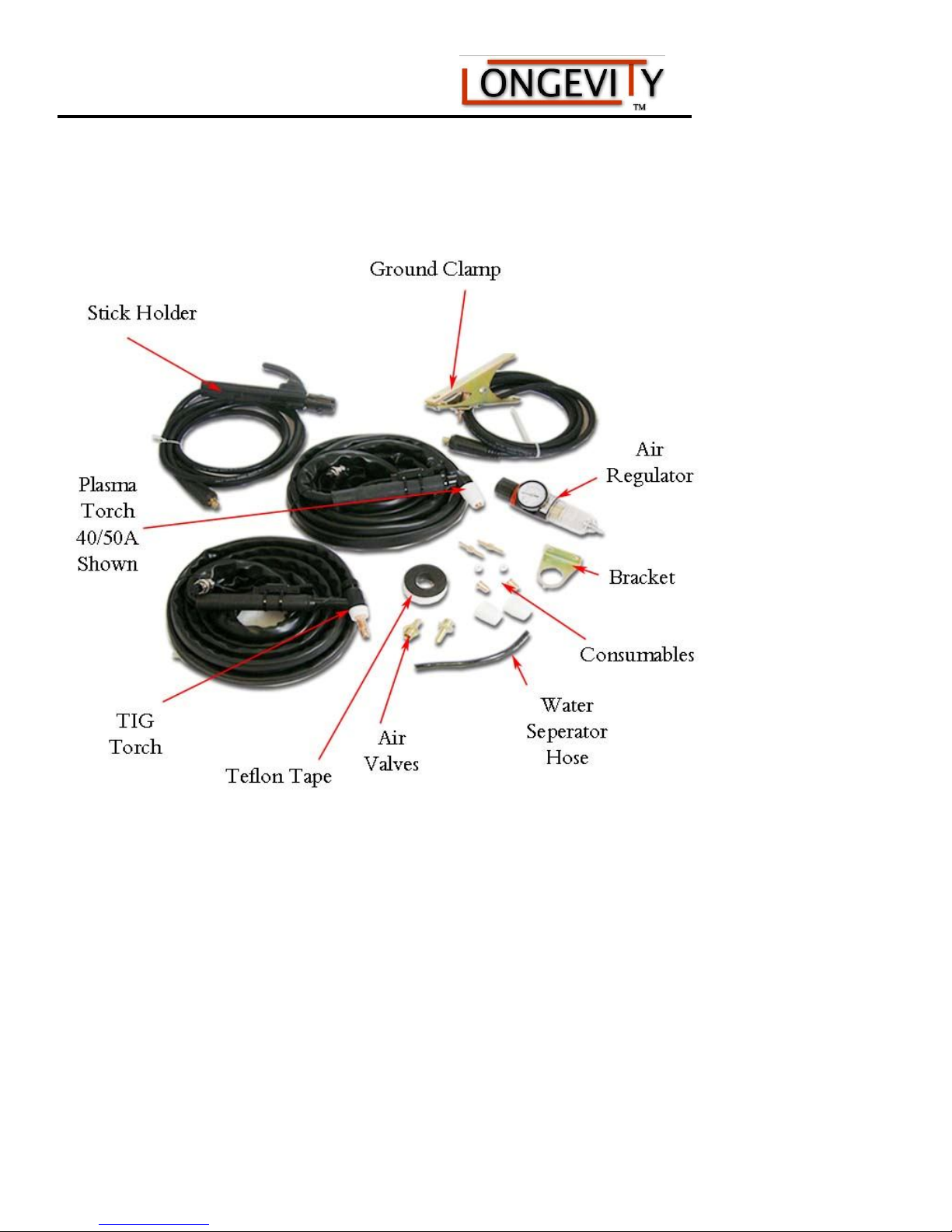
What’s Included?
www.longevity-inc.com
Page 13
160/200/160P/200P AC/DC Series Machine
Installation, Wiring, and Setup Instructions:
The item numbers referenced in the following paragraphs, refer to the numbered parts display in the diagrams
shown below. LONGEVITY® has an instructional setup installation video on our website at www.longevity-
inc.com, which we ask that you view prior installing the unit. The video shows the complete assembly of the
machine. The video is located in the Resources section of the website under manuals and installation/set-up
videos.
The LONGEVITY® WeldMax Plasma Cutter/Welder Combo units are dual voltage and can be connected to
either 110 or 220VAC.
Connecting the electrical plug to the unit
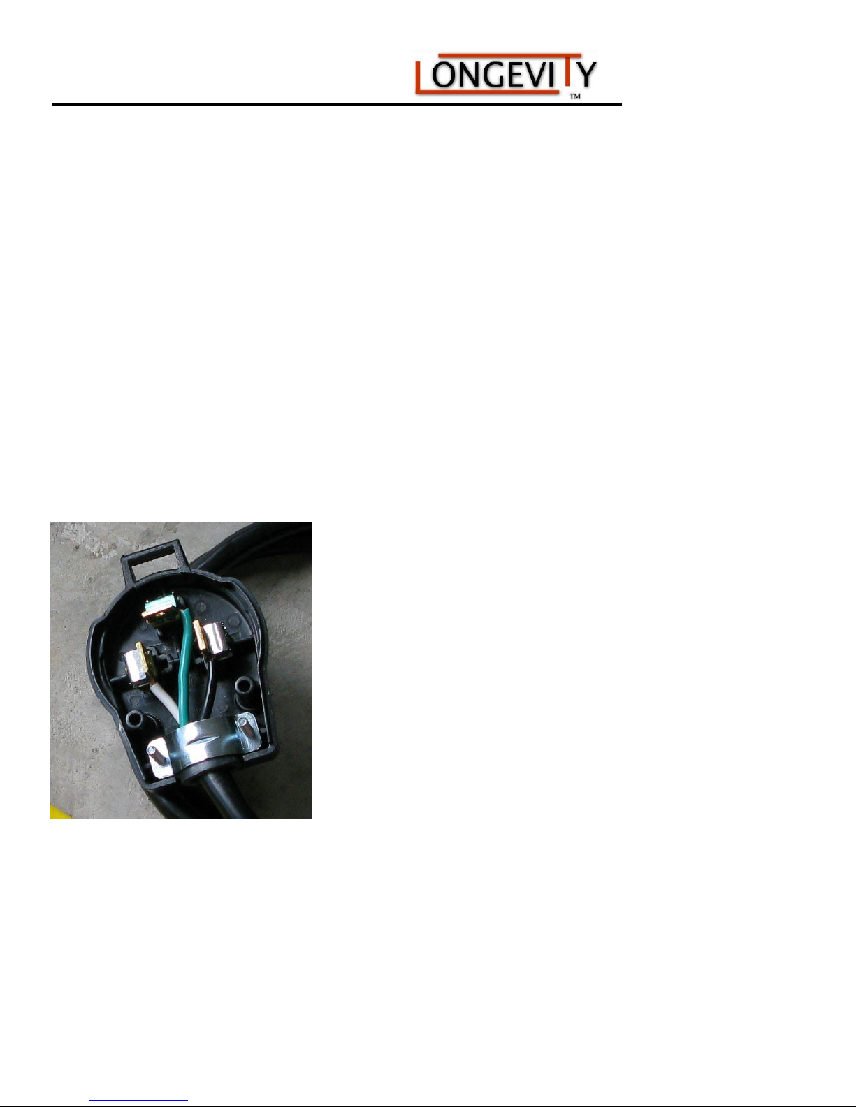
Connecting the power plug to the unit is important. Please view the proper connection instructions below:
Wiring Introduction for 220 Volt
Danger: Read this manual completely before having your electrician attempt to wire up or connect your
machine to an electrical power source. LONGEVITY® units should be wired by a certified electrician to insure
your safety and a proper 110/220v plug match at your operating facility. Remember 220v plugs come with 3 or
4 prongs on them. Have the electrician check your existing receptacle.
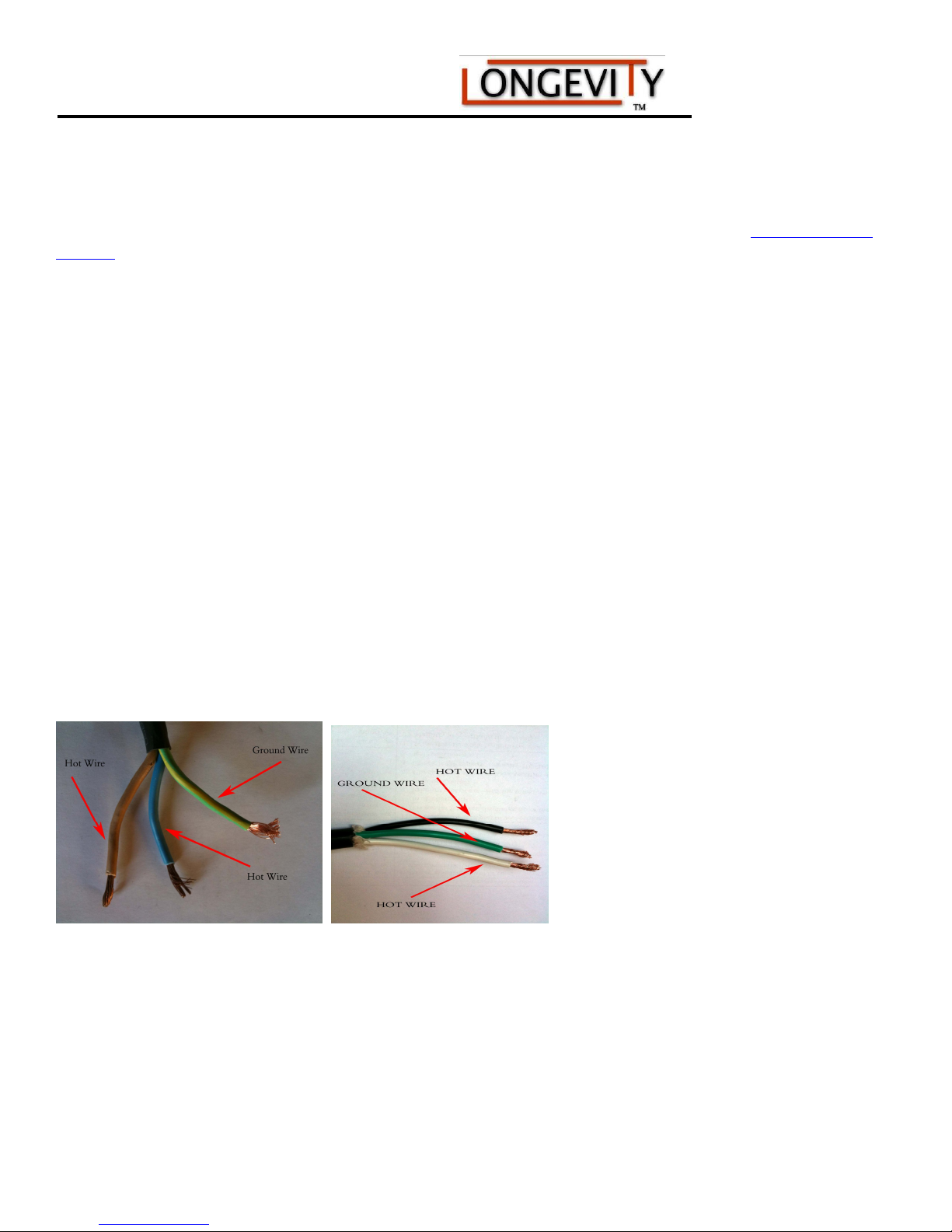
Note: The power cord on single-phase machines has one ground wire and two hot wires when connecting to
220vac. Connecting these wires properly is extremely important. Improperly connected wires will void the
warranty, affect personnel safety, and possibly damage your machine and electrical power outlet.
Identifying
Caution: The machine may appear to operate with an incorrectly connected ground wire, but it will not operate
properly. Selecting the correct ground wire is important for proper machine operation and personnel safety.
Ground wires on LONGEVITY® Welding machines are usually one of the following colors:
The ground wire is a dark green with a yellow stripe. The wire may also be just SOLID GREEN.
Clean the ends of the wires to more easily distinguish the colors. The best and safest way to determine which
www.longevity-inc.com 11
the Ground wire
Page 14
160/200/160P/200P AC/DC Series Machine
wire is ground is to measure the resistance between the machine chassis and the selected wire, using an
ohmmeter. Another method is to check the continuity between the chassis and the wire, using a continuity
meter. If the selected wire is ground, the connection between the chassis and the wire will cause the meter to
illuminate. If, for any reason, you cannot visually detect the ground wire or do not feel comfortable with your
selection, ask an electrician for help.
Identifying
For 220vac service, both the brown and blue wire are positive wires. As you may know, 220vac features
two hot wires. If you are wiring to 220vac, your blue and brown wires are both hot. The green with yellow
or SOLID GREEN is the ground. Remember, any hot wire can be attached to either hot leg on the plug.
Note: Hot Wires May also be WHITE and BLACK if a GREEN WIRE is one of the three wires. Therefore,
GREEN is ALWAYS GROUND.
NOTE: LONGEVITY® recommends a 50 AMP breaker on 220v, but you can operate on 30AMP breaker.
the hot wire
Finished Plug:
www.longevity-inc.com
Page 15
160/200/160P/200P AC/DC Series Machine
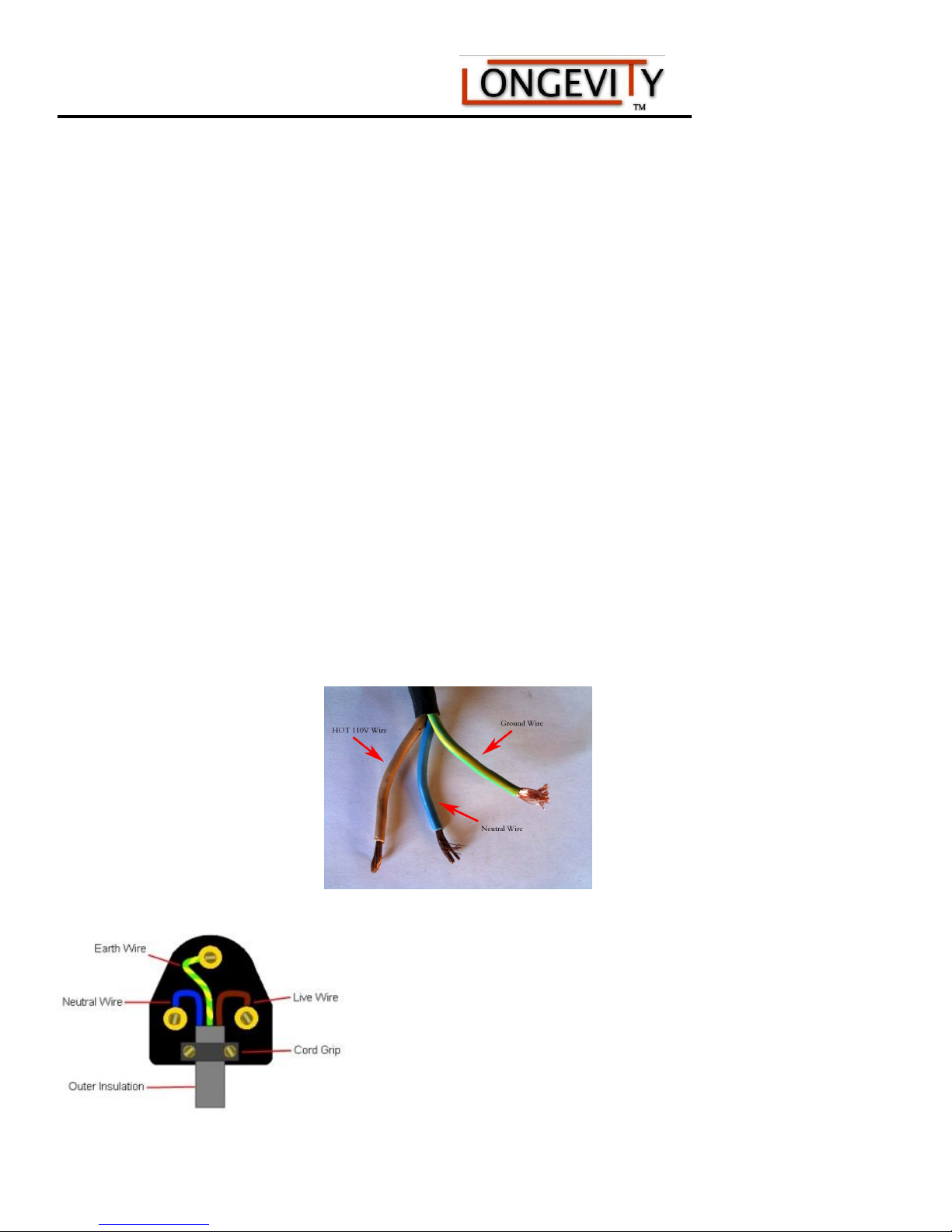
Wiring Introduction for 110 Volt - 20amp Breaker
Caution: The machine may appear to operate with an incorrectly connected ground wire, but it will not operate
properly. Selecting the correct ground wire is important for proper machine operation and personnel safety.
Ground wires on LONGEVITY® Welding machines are usually one of the following colors:
The ground wire is a dark green with a yellow stripe. The wire may also be just SOLID GREEN.
Clean the ends of the wires to more easily distinguish the colors. The best and safest way to determine which
wire is ground is to measure the resistance between the machine chassis and the selected wire, using an
ohmmeter. Another method is to check the continuity between the chassis and the wire, using a continuity
meter. If the selected wire is ground, the connection between the chassis and the wire will cause the meter to
illuminate. If, for any reason, you cannot visually detect the ground wire or do not feel comfortable with your
selection, ask an electrician for help.
Identifying the Neutral Wire
For 110vac service, the brown wire is is a hot wire. As you may know, 110vac features one hot wire, a
neutral wire, and a ground wire. If you are wiring to 110vac, your blue wire is neutral, brown is hot and
the green with yellow or SOLID GREEN is the ground.
Note: Hot Wires May also be WHITE and BLACK if a GREEN WIRE is one of the three wires. Therefore,
GREEN is ALWAYS GROUND. In this case one of the wires is neutral and one is hot.
NOTE: LONGEVITY® recommends a 20 AMP breaker on 110v
110V Plug Diagram:
www.longevity-inc.com 13
Page 16
160/200/160P/200P AC/DC Series Machine
Main Unit
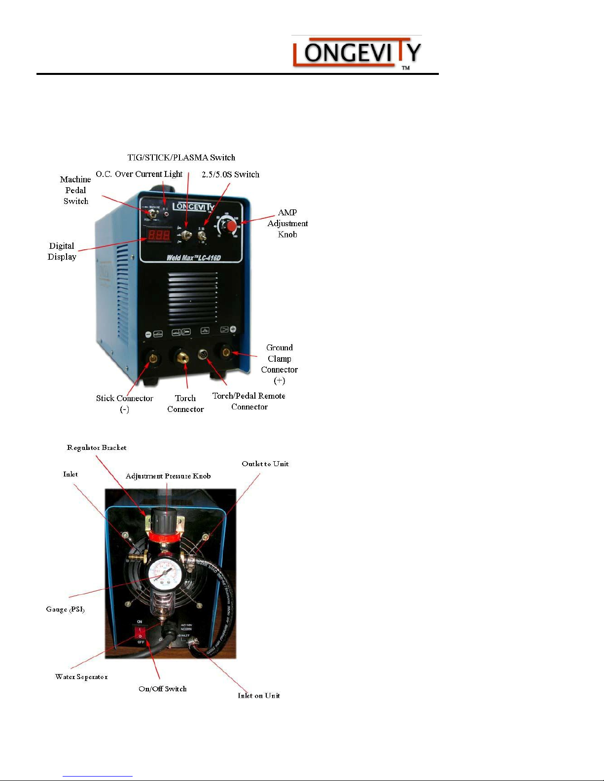
Pictured: WeldMax 416D Multi-Purpose Unit
www.longevity-inc.com
Page 17

160/200/160P/200P AC/DC Series Machine
Main Unit Knob/Button/Function:
1. On/Off Breaker or Switch: Either breaker or switch located on the back or front of the unit will control the unit to
be turned on or off.
2. Power Indicator : Shows unit is powered on. Indicator is present in some models with a green LED bulb.
3. O.C. Over Current Light: Illuminates when the duty cycle has been exceeded or the machine has overheated due
to improper ventilation. Discontinue use until lamp goes out. Allow the fan to continue to run. Once lamp goes out,
you may resume using the unit.
4. Digital Display: Displays the approximate amount of amperage set to on the unit.
5. Gas (Air) Test/Cutting: This mode allows you to test air pressure and release air through the torch. Selecting Gas
(Air) Test, you should have air passing through the torch as long as the compressor is on. Cutting mode allows you
to use the plasma cutter normally.
6. AMP Adjustment Knob: Adjusts the amount of amps to desired AMP setting.
7. Ground Clamp Connector (+): Location of ground clamp to be plugged in and ran to the workpiece.
8. Stick Connector (-): Connect the stick welding rod here. You can also reverse polarity by switching the ground
clamp
9. Torch Remote Connector: 2 or 7 pin torch connector plugs here to activate the torch relay once the trigger is
pressed on the torch.
10. Torch Connector: Connect torch for air to pass through the unit and generate the arc at the torch tip.
11. Torch Air Outlet: This is only used with specific torches that require water cooling. Your unit does not come with
this feature as it is not required.
12. Air Regulator Pressure Gauge: Shows the amount of pressure at the torch in PSI.
13. Pressure Regulator Adjustment Knob: Adjust the amount of pressure at the unit. Pull the knob towards you or
up to unlock, turn clockwise for more pressure and counter clockwise for less pressure. Once the desired pressure
is reached, pop the knob back in place to lock it in place.
14. Thermal Protection Fan: Cools your unit during operation. Fan should be operating once the power is turned on
and the unit power indicator is lit.
15. 110/220v Power Cord: Attach the power cord to the wall outlet for unit power.
16. Ground Lug: An additional safety grounding lug. You can earth this wire or properly ground it to your
electricians specifications. Grounding the unit and yourself during cutting is extremely important
17. Air Inlet: Attach air compressor hose to the air inlet here.
18. Machine/Pedal: Select Pedal, when pedal is plugged into the machine.
www.longevity-inc.com 15
Page 18
160/200/160P/200P AC/DC Series Machine
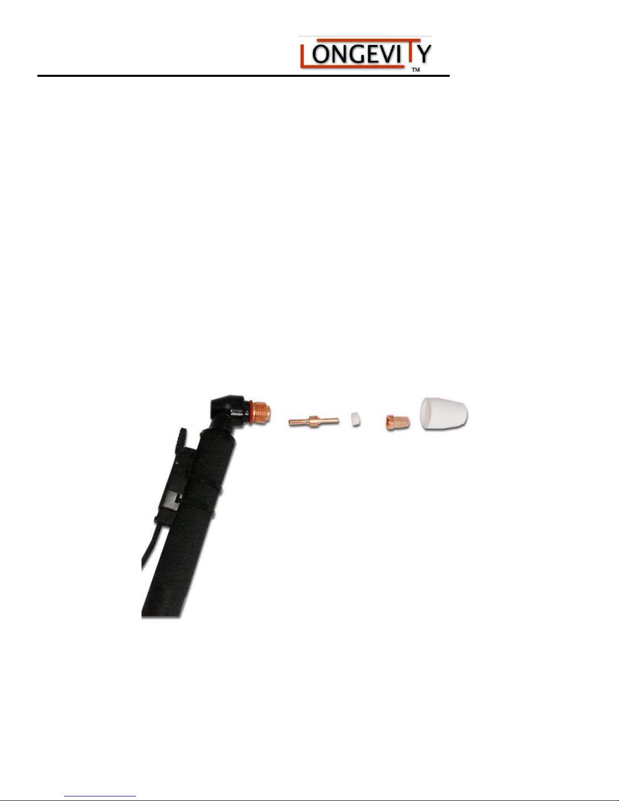
Assembly of Plasma Torches:
The plasma cutter torch handle is made of fire and heat resistant materials. Avoid dropping the torch or striking
anything with it. For convenience and ease of use, the torch’s ON/OFF switch can be positioned on the top, the
side, or the bottom of the torch body.
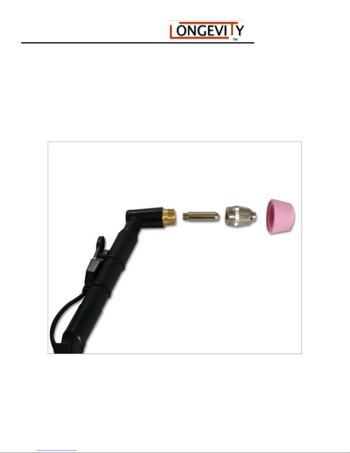
Assembly of Consumables for the 40/50AMP Torch Heads
Assemble the consumables as pictured above, and described below.
1. Insert the electrode.
2. Seat the ring on the electrode.
3. Place the copper tip on the ring, ensuring that is seated flat.
4. Secure all parts into place by turning the ceramic cup clockwise until it is snug. Do not over tighten.
The torch consumables are now successfully assembled.
www.longevity-inc.com
Page 19
160/200/160P/200P AC/DC Series Machine
Assembly of Consumables for the 60AMP Torch Head
Assemble the consumables as pictured above, and described below.
1. Insert the electrode.
2. Place the copper tip on the ring, ensuring that is seated flat.
3. Secure all parts into place by turning the pink ceramic cup clockwise until it is snug. Do not over
tighten.
The torch consumables are now successfully assembled.
www.longevity-inc.com 17
Page 20
160/200/160P/200P AC/DC Series Machine
Air Regulator Assembly to Unit
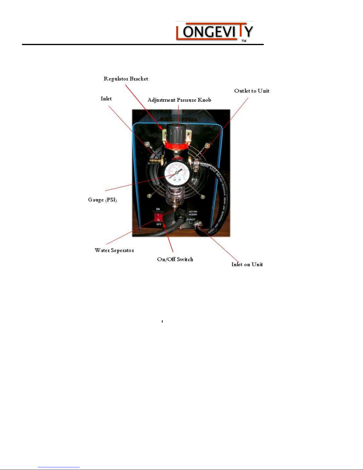
LONGEVITY® includes an air regulator/filter with your machine. You must attach the bracket to the machine,
and fasten the regulator to the bracket so it looks as pictured
1. Locate the INLET and OUTLET labeled on the regulator picture above and attach the Air Compressor
to the inlet and the OUTLET to the INLET on Unit with the provided hose to back of the machine,
where shown, and secure it with a hose tie.
2. Set the air compressor to about 60-75 PSI depending on the thickness of your cut. If you are getting a
poor cut quality, try adjusting the PSI on the regulator to see if the cut quality improves.
3. Periodically, after long periods of use, you must remove water from the air by pushing the water release
button inward to release water from the water separator section of the regulator.
www.longevity-inc.com
Page 21

160/200/160P/200P AC/DC Series Machine
after you read the manual and before you get started. Below are a list
Plasma Cutter Operating Tips from www.plasma-cutters.com
Tips For Longevity Plasma Cutting
Using a Longevity Plasma Cutter with either High Frequency or
Pilot Arc technology is very easy to use, and since each Longevity
unit is quality tested at our in house testing facility before it is
shipped , most of our customers take right out of the box, plug it in
and get to work. Naturally, it is easy to understand how excited you
would be to see the delivery truck pull up with your brand new
Longevity Plasma Cutter and you should be. Congratulations is in
order and we want to ensure you have the best experience with your
Longevity Plasma Cutter. However, excited as we are you can't wait
to put your Longevity Plasma Cutter into action, we would like you
to consider these helpful tips and examples that will enable you to
get the most out of your Longevity Plasma Cutter and it's
consumables. So, before using your Longevity Plasma Cutter it is
extremely important to read the owner's manual all the way through
regardless of your experience level. Even if you are a seasoned
veteran, give it a once through and keep it near by in case you,
someone you know or someone you work with has a question about
the use or specifications of your Longevity Plasma Cutter.
At this point, let us assume that you have purchased the Longevity
Plasma Cutter that is right for you, and even though you did your
research already, it is always a good idea to revisit the safety
precautions, specifications and unique options ensuring you achieve
the most with your Longevity Plasma Cutter while staying safe. In
case you have not decided which Longevity Plasma Cutter is right
for you, please visit the Help Me Choose section and take advantage
of the Longevity Smart Selector.
In terms of safety, the price of carelessly cutting corners can be
extremely costly, not only to your health but to the people around
you as well. So, before you get started using your Longevity Plasma
Cutter to create your master piece, build a bridge, or whatever you
want to do, make sure you have a quality safety checklist you follow
of tips and safety measures you might find useful in developing your
safety checklist. Remember, in no way shape or form does this
checklist or any other check list ever replace the necessity of
thoroughly reading the owner's manual of your Longevity Plasma
Cutter.
www.longevity-inc.com 19
Page 22

160/200/160P/200P AC/DC Series Machine
Cutter and consult your owner's manual to ensure the
Pilot Arc or High Frequency technology, comes with
your consumables are clean, correct,
No
Check List Suggestions
Connect the air supply to your Longevity Plasma
correct PSI. The PSI is about 65-75.
Each Longevity Plasma Cutter, regardless if it uses
an air flow regulator and water catcher. Reference
the owner's manual of your Longevity Plasma Cutter
for specifications and care instructions of your air
flow regulator and filter.
Check the torch of your Longevity Plasma Cutter
and make sure everything is in order. Reference the
owner's manual of your Longevity Plasma Cutter to
make sure all of
and pieced together securely before you begin
cutting.
Gouging or piercing can be achieved by simply
lowering the amperage output and keeping with the
recommended psi. Examples on how to achieve the
desired results can be referenced in the owner's
manual of your Longevity Plasma Cutter.
w you are ready to use your Longevity Plasma
Cutter safely and efficiently. Turn the machine on
and enjoy the satisfying experience of a quality
Longevity Plasma Cutter.
Double check your air supply, air flow regulator and
water filter. (More on this below.)
All Longevity Plasma Cutters require a solid ground
connection as close to the work piece as practical.
Remember, even though your Longevity Plasma
Cutter can cut through paint and other coatings on
the metal, the ground connection requires a clean,
flush connection to the work piece.
Utilizing the proper safety equipment is just as
important as understanding how to properly operate
your Longevity Plasma Cutter. Consult the owner's
manual of your Longevity Plasma Cutter to be sure
you are using the correct gloves, eye protection,
welding leathers, face shield, etc. You can find all of
the necessary equipment as stated in the owner's
manual of your Longevity Plasma Cutter in the
www.longevity-inc.com
Page 23

160/200/160P/200P AC/DC Series Machine
When cutting a thicker material with your Longevity Plasma Cutter
accessories section of our website.
Longevity Plasma Cutter Tips
In order to successfully execute a clean cut with your Longevity
Plasma Cutter you must consider a combination of elements involved
in the cutting process:
The old adage says to measure twice and cut once,
but we want to go ahead and suggest you make a
sample cut (of the same caliber as the intended use)
with your Longevity Plasma Cutter before you get
started. Use this rehearsal just to be sure you have
correctly calibrated all the settings to work as
desired. If you are going to be cutting for a large
piece of metal, it can sometimes be difficult for even
the most experienced metal worker to cleanly stop
and start. We recommend you use the sample cut to
thoroughly rehearse the intended cut with your
Longevity Plasma Cutter.
The tip of your torch is designed to focus the plasma stream to the
work piece in accordance with the appropriate setting (see owner's
manual). Trying to use a 80-amp torch tip at a 40-amp setting will
not focus the energy of your torch accurately and thus lead to a
wider kerf. And the opposite scenario of using an 80-amp setting
with a 40-amp tip will abuse your torch tip and require it to be
replaced sooner than intended.
it is important to use a torch tip designed for a higher-amp output.
Higher-amp tips have a larger opening than lower-amp tips.
Attempting to use a 40-amp tip to cut thick metal with a higheramp output will distort your 40-amp tip meaning it will need to be
replaced.
Each Longevity Plasma Cutter, both Pilot Arc and High Frequency
, allow you to cut different metals at different speeds. For example
to achieve a quality cut of 1/2in. thick steel with the Longevity
Force Cut LP-40D Pilot Arc your speed will be roughly 7 inches
per minute. Where as the Longevity Force Cut LP-80D will cut
1.25in. thick steel at the same rate.
Use extended tips on your Longevity Plasma Cutter for tough to
reach corners, tracing a pattern, or areas with tight spaces.
Pilot Arc technology allows you to ignite the arc without the tip
touching the metal. Use a torch guide or tip shield to protect your
www.longevity-inc.com 21
Page 24

160/200/160P/200P AC/DC Series Machine
of
*
your Longevity Plasma Cutter torch tip. In order to maintain the quality
and take advantage of the protective gear you have like our guys on the
ituations when you are going to be cutting thick metals at
high amperage with your Longevity Plasma Cutter, we recommend you
consumable. The more often you drag your torch tip across the
material or stop and restart the Pilot Arc, the shorter the life span
your consumables will be.
Using a torch guide or tip shield is a great way to protect the
consumables of your Longevity Plasma Cutter. Remember to
maintain a 1/16in. - 1/8in. distance from the material when cutting.
The important things to consider while using your Longevity Plasma
Cutter to cleanly execute a cut is correct amperage of the torch tip,
thickness of the material, intended speed, proper technique, and
ultimately protecting the life of your consumables.
Cutting Posture
Sometimes you may find that you are unable to use a guide or shield
when operating your Longevity Plasma Cutter. In some instances a
project may be a very ornate design with different curves and
protrusions or the material is too thick to apply a shield or guard to
and consistency of your work we recommend that you use your other
hand as a guide. Give yourself a fighting chance to steady your hands
Longevity Facility Testing Team .
One of the reasons you purchase a Longevity Plasma Cutter is
because of it's quality. Therefore, we think you should have a
few quality reminders to think about when you are cutting.
If you stop and start an arc in the middle of a cut, often the the quality
of your cut will suffer and compromise the integrity of your so far
clean cut-line. Remember, even when we do facility testing, a suitable
method to apply when using your Longevity Plasma Cutter is
rehearsing the cut. Be sure you are going to be able to produce a
smooth continuous cut-line all the way through.
Along with rehearsing your cut, another equally good reminder is to
protect your consumables as much as possible. Often we can get
comfortable piercing right through thin steel with our Longevity
Plasma Cutters, but when cutting thicker metal often the intense back
splash from initial contact will rapidly wear down your torch tip and
other consumables. Even though the seeing the bright sparks show off
the awesome power of your Longevity Plasma Cutter, remember we
want you to be able to enjoy the results of your work time and time
again. So, in s
start with the torch pointed at a 45 degree angle. This angled approach
allows for the first blast of metal to be released with out back splash on
www.longevity-inc.com
Page 25

160/200/160P/200P AC/DC Series Machine
you move on a material such as aluminum, the cleaner your cut will be.
accordingly. Thin material requires you to turn down the amperage and
Figuring out if you are going too slow or too fast can be a daunting task
20 degree angle,
be wary of the torch tip because of electrical conductivity of aluminum.
to your valuable consumables.
Know Your Amperage, Know Your Metal
At www.longevity-inc.com, you can see the cutting thickness
capability.
Understanding the amperage in relation to your cut speed is important.
Some metals respond differently than others. For example the faster
Conversely, when using your Longevity Plasma Cutter to cut thicker
material, set your unit to full output and vary your travel speed
change to a lower-amperage to achieve a narrow kerf.
that really only comes with time and experience. However, our guys in
the Longevity Facility Testing Team have a few pointers for you:
If your cut has a lot of spray back then you are probably going
too fast.
If the arc exits the material going straight down then you are
probably moving too slow and you will have an unnecessary
buildup of "dross" or "slag."
Your arc should be exiting the material at a 15 but opposite the direction of your cut path.
Using A Cutting Guide
First thing in using a torch guide with your Longevity Plasma Cutter is
make sure it isn't flammable! Aluminum works as a great torch guide,
but be sure it is attached to the torch cup and not the torch tip.
Aluminum is a great contact guide because of it's smooth surface but
It would be a terrible mess of a cut, loss of consumables, and overall
depressing mistake if your torch guide melted to the torch tip or the
project at hand. Next you want to mark the material to be cut with
either white chalk or a black marker. If you are unsure of how steady
your hands are, we recommend you try using a straight edge clamp
attached to the work piece or torch guide.
All articles are composed by the Longevity Facility Testing Team and
are written with expressed interest of maintain a strong standard in
Longevity Global Inc. quality, to help address topics, and answer
questions for amateur and experienced users alike. Please remember to
always exercise extreme causation and abide by all provided safety
www.longevity-inc.com 23
Page 26
160/200/160P/200P AC/DC Series Machine
specification.
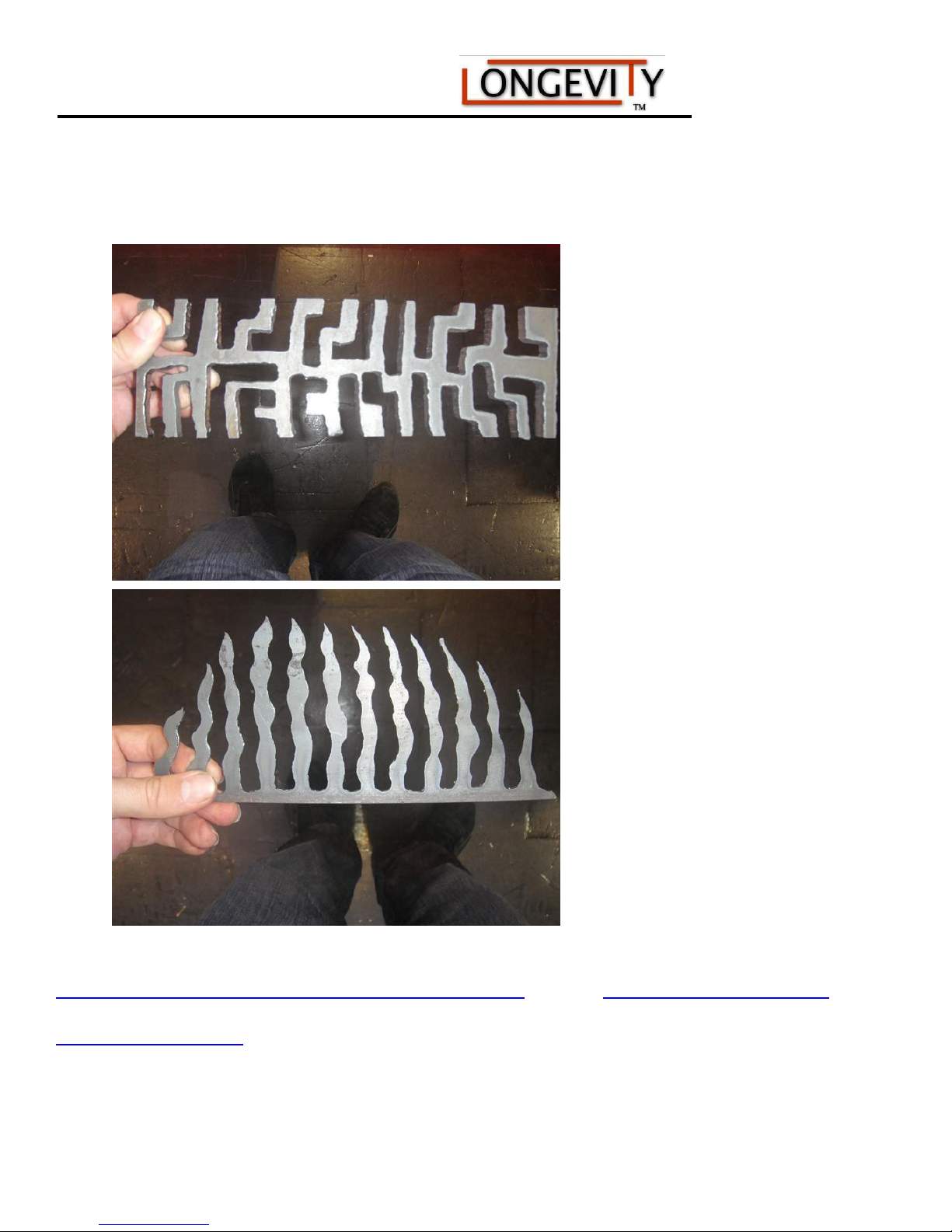
Sample Photos:
For more information on plasma cutting from professionals go to
www.freeweldingforum.com and www.plasmacutters.com
www.longevity-inc.com
Page 27
160/200/160P/200P AC/DC Series Machine
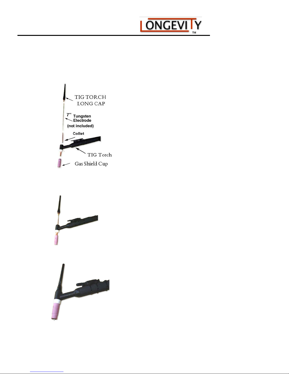
TIG Section: Setting Up The TIG Torch
www.longevity-inc.com 25
Page 28

160/200/160P/200P AC/DC Series Machine
enerally utilized for DC welding of mild steel, bronze, and stainless steel and
weld aluminum. We recommend this tungsten
purpose welders, which feature DC
orks well with Inverter Welders. This is the tungsten to use for your
Selecting the Right Tungsten Electrodes:
Selecting the right tungsten is crucial to a successful TIG weld. You have to insure the correct tungsten is used
for the type of metal you are welding, the type of technology used in your welder such as transformer or
inverter, and the thickness of the metal you will need to weld. This leaves you with a variety sizes ranging from
1/16 to 1/8” and the types of tungstens such as the Pure Tungsten (TP), 2% Thoriated Tungsten (TT2), 2%
Ceriated Tungsten (TC2), and 2% Lanthanated Tungsten (TL2). Fortunately, LONGEVITY offers high quality
tungsten electrodes and explains which tungsten is required for the right application. Pure Tungsten (TP) –
(green tipped) - Pure tungsten readily forms a ball on the end. It is designed for use with transformer-based
power sources for AC welding of aluminum. Unfortunately, LONGEVITY does not carry transformer based
technology considering the size and weight of TRANSFORMER welders. Therefore, this tungsten is rarely sold
buy our sales staff
2% Thoriated Tungsten (TT2) – (red tipped) - This tungsten is the most common tungsten currently being used
with LONGEVITY DC TIG. It is g
basically all metals except aluminum and offers excellent performance. A drawback is that this tungsten has a
low level radiation hazard and the fact that they no recommend to
with our stand alone DC only TIG Welders, our WeldMax series multi-
TIG welders. The 2% Thoriated Tungsten w
welder. LONGEVITY does have them available.
2% Ceriated Tungsten (TC2) – (grey tipped) – 2% ceriated is an excellent substitute for 2% thoriated tungsten
and is designed for transformer and inverter based power sources. For Transformer DC welding, this tungsten
requires less amperage to start so it is recommended for thinner metals. It offers a stable arc and can be used for
both AC and DC welding with inverter power sources and is our most popular sold tungsten because it can be
used to weld every type of metal in both AC / DC modes in our LONGEVITY INVETER TIG welders. We
recommend this unit with our ArcMate 200AMP ACDC TIG/STICK unit or our WeldAll series multi
functional welders and plasma cutters because of the versatility of AC DC welding.
2% Lanthanated Tungsten (TL2) – blue tip – 2% lanthanated is probably the most popular substitute for 2%
thoriated tungsten. Offering a longer life span than the 2% thoriated tungstens, it is a nice a nice alternative, but
not as recommended as our 2% Thoriated Tungsten. This tungsten can be used with both transformer and
inverter technology on both AC DC modes.
www.longevity-inc.com
Page 29
160/200/160P/200P AC/DC Series Machine
Tungsten Chart Guide
Tungsten Type Diameter
040"(1.0mm) 1/16"(1.6mm) 3/32"(2.4mm) 1/8"(3.2mm)
Pure Tungsten TP-7040 TP-7116 TP-7332 TP-718
2% Thoriated TT2-7040 TT2-7116 TT2-7332 TT2-718
2% Ceriated TC2-7040 TC2-7116 TC2-7332 TC2-718
2%
Lanthanated
TL2-7040 TL2-7116 TL2-7332 TL2-718
Amparage-Ac 20-30 30-80 60-130 120-200
Amparge-Dc 15-50 50-120 80-150 130-250
Sharpening a Tungsten
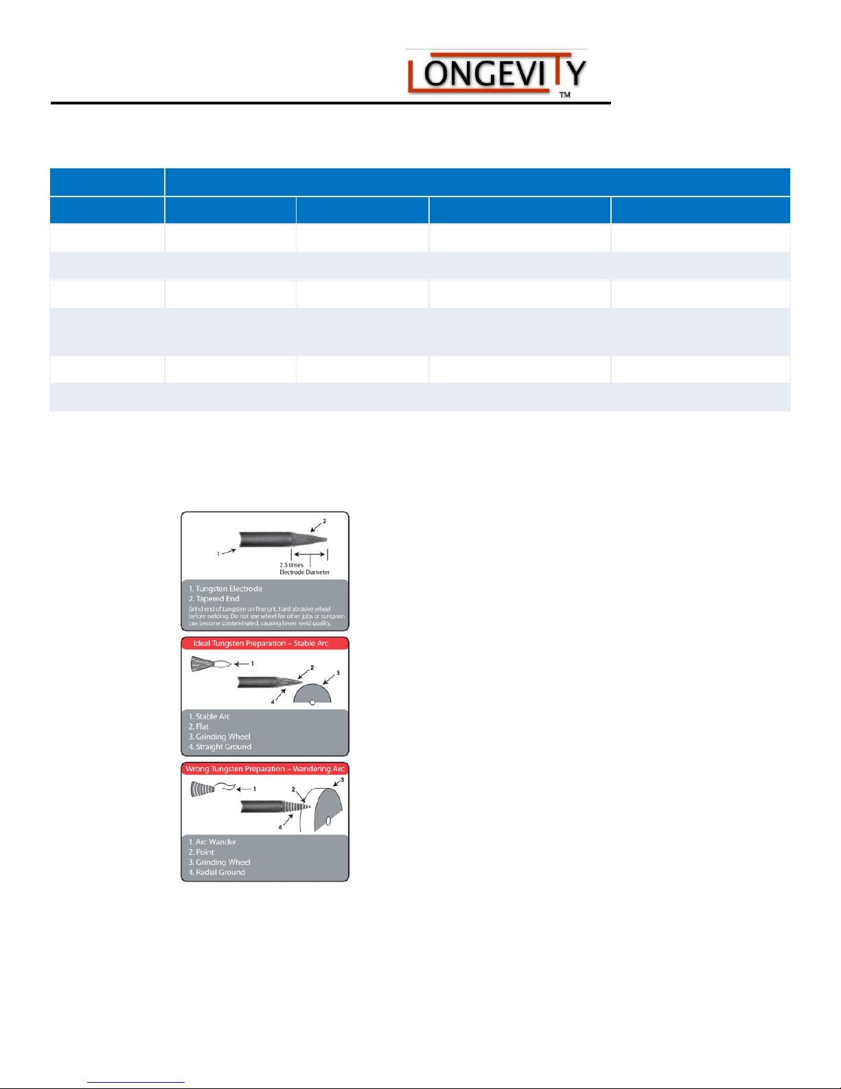
Sharpening a tungsten is very important for a nice fine arc strike. There are auto sharpeners to place the perfect
sharpening point on your tungstens or you can simply use a grinding wheel to sharpen your tungsten.
Remember, after sharpening to a pencil point, you want to flatten the bottom for a good arc.
www.longevity-inc.com 27
Page 30

160/200/160P/200P AC/DC Series Machine
Selecting the right FILLER RODS FOR TIG WELDING:
Filler Rods are essential to TIG Welding because the filler rod is fed into the molten puddle by hand filling in
the puddle to create a stronger metal bond or puddle to join two metal pieces. It is extremely important to have
the right filler rod based on the metal you are welding. It is also necessary to have the right tungsten to insure
you are properly setup to weld your metal.
Part # Application:
4043-1/16-1 4043 Alloy Aluminum Wire 1/16" X 36"
4043-3/32-1 4043 Alloy Aluminum Wire 3/32" X 36"
5356-1/16-1 5356 Alloy Aluminum Wire 1/16" X 36"
5356-3/32-1 5356 Alloy Aluminum Wire 3/32" X 36"
308L-035-1 308L Stainless Steel Wire .035” x 36”
308L-1/16-1 308L Stainless Steel Wire 1/16" X 36"
70S6-1/16-1 ER70S-6 Steel Wire 1/16" X 36"
70S6-3/32-1 ER70S-6 Steel Wire 3/32" X 36"
70S2-1/16-1 ER70S-2 Steel Wire 1/16" X 36"
80SD2-1/16-
1
Longevity offers quality filler rods at affordable prices. Please take a look at the selection of filler rods that we
carry to decide what the best application of rod will be for your weld.
ER80SD-2 Steel Wire
E1/16" X 36"
Your choice of filler rod is extremely important to the strength and matter density of your weld. You can
determine the diameter of the filler rod needed, by the thickness of the material that you will be welding. Here
are some pointers in deciding how to choose the correct filler rod for your weld.
1. 4043 is a general filler rod for most aluminum welding. Remember, the WeldMax series is strictly DC
welding so aluminum is not possible with the use of Argon.
2. 5356 is perfect for 5xxx series aluminum. If you are planning on anodizing the finished piece, this rod
should be used for the weld.
3. ER70S-6 is designed for welding mild steel.
4. ER70S-2 is recommended for welding 4130 chrome moly tubing in most applications.
5. ER80S-D2 is for welding 4130 chrome moly tubing if a higher strength weld is required.
6. 1/16” diameter filler should be used when material is 1/8” and less thick. 3/32” diameter filler rod can be
used for 1/8” and thicker material. For more info on Filler Rods, go to www.freeweldingforum.com
www.longevity-inc.com
Page 31
160/200/160P/200P AC/DC Series Machine
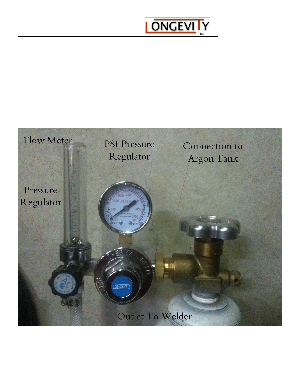
Setting Up the Argon Regulator:
The argon regulator (pictured below) is included with your unit. Setting it up to your argon bottle is
easy. Simply screw in the valve to the bottle and set the pressure to about. Use 100% Argon at 15-25
CFH (cubic feet per hour). Set the gas flow using the regulator on the gas bottle. Use higher flow when
extending the tungsten electrode to reach into corners or gaps. We recommend about 18 CFH. Remember, that
you also have a post flow setting on the unit to pass more argon after the arc to cool the electrode.
Argon Regulator Assembled.
www.longevity-inc.com 29
Page 32

160/200/160P/200P AC/DC Series Machine
Basic TIG Operation
(Tungsten Inert Gas - Gas Tungsten Arc Welding - GTAW)
TIG Operation and Principles:
Shielding Gas: Use 100% Argon at 15-25 (cubic feet per hour). Set the gas flow using the regulator on the gas
bottle. Use higher flow when extending the tungsten electrode to reach into corners or gaps.
Tungsten Electrode: We recommend 2% Thoriated tungsten (red) for TIG welding with our DC TIG welders.
Use smaller diameter electrodes for thinner metal (low amperage), thicker electrodes for thicker metals that
require more amperage. For the right tungsten electrode, please refer to earlier in this manual or go to
www.longevity-inc.com
Filler Rod Selection: Depending upon the metal to be welded, filler rod selection is critical. Consult with your
local welding supplier for the optimum filler rod to properly complete the weld. In certain applications, TIG
welding can be performed without the use of a filler rod. Use free welding forum at
www.freeweldingforum.com to gather advice or go to www.longevity-inc.com.
Pre-TIG Welding
As you get to know the above information of basic TIG welding applications, there are a couple of basic steps
that need to be taken. The tungsten must be sharpened and shaped before initiating an arc. With inverter TIG
welding machines, tungsten sharpness is important. Your weld’s outcome will be partially determined by the
shape of your tungsten. Sharpening an electrode consistently will cause an unstable, wandering arc, making it
more difficult to control the weld puddle. Carefully rotate the tungsten as it is being ground to prevent a flat
spot or a hollow ground point. Also note that tapering the tungsten to 2.5 times of its diameter is generally
recommended for most DC welding applications. For high amperage DC welding, do not over sharpen the
point, but leave a slight truncation on the end of the tungsten. This prevents the tungsten tip from breaking away
and falling into the weld. It is also normal for a slight dome to form on the tungsten in DC mode. However, if
the arc becomes erratic or the arc is difficult to start, regrinding the tungsten will be necessary. If the tungsten is
accidentally dipped into the weld puddle, regrinding the tungsten will be necessary to eliminate contamination,
particularly on aluminum. Grind tungsten’s only on a dedicated stone, free of contamination from other metals.
Starting a TIG Weld: Filler rod selection is critical to a TIG welds density, strength and purity. Check out our
filler rod selection chart on our website for optimum filler rod to properly complete a weld. In certain
applications, TIG welding can be performed without the use of a filler rod. One of the biggest issues for
beginning welders is holding and maintaining an arc. Starting an arc with your High Frequency welder is quite
simple. Set the machine for TIG operation then select the desired amperage. Grasp the torch in a manner that is
comfortable to you. Place the torch so that the tungsten is no more than 1/8 inch from the weld surface.
Depending upon the setup, either press the foot pedal down or press the trigger to initiate the high frequency
arc. A small blue glowing cone may be observed. This is the high frequency arc. Immediately after that, you
www.longevity-inc.com
Page 33
160/200/160P/200P AC/DC Series Machine
should see a strong and stable arc flowing from the torch. As the arc begins to grow, a molten puddle will
appear. If it does not appear, stop your weld and increase the amperage. Repeat the start sequence.
1. To help the molten puddle form, slowly make small circles with the torch to build the heat in the weld area. A
bright, fluid puddle will begin to form.
2. Once a uniform puddle is established, tilt the torch head about 75 degrees from the weld surface into the
direction of the weld. This will direct the arc to the front of the weld puddle.
3. Grip the filler rod at a 15 degree angle to the weld surface with the other hand. Hold the rod in the iridescent
cone of gas that surrounds the weld puddle. Do not hold it in the arc. Keep it close to the weld. A “skeleton”
keyhole will begin to form in front of the weld. The keyhole is evidence that you are ready to add filler material
and move forward. Introduce the filler rod into the key hole area underneath the arc. Wait for a single molten
drop to fall off the tip of the rod.
4. When a molten drop falls from the rod, quickly remove the rod, keeping it inside the gas cone. The molten
drop of filler metal should blend quickly into the puddle.
5. Move the torch forward slightly, carrying the keyhole with the weld. If the key hole is lost, then forward
travel was too fast or too far. When the keyhole shows good development, repeat the steps 3-5 until you have a
proper weld bead established.
6. Weld termination. When the weld bead has reached the desired length, add a final drop of filler and slowly
circle the torch over the end of the weld to fill the crater. If the weld crater is not correctly filled, cracking and
weld failure may occur. This is a small but important step to properly completing a weld. Release the foot pedal
or release the trigger to stop. Keep the TIG torch in place until the post flow ends--usually around 5 seconds.
7. When finished welding always let the welder's fan run for a minute or two to cool the machine before turning
the power switch off.
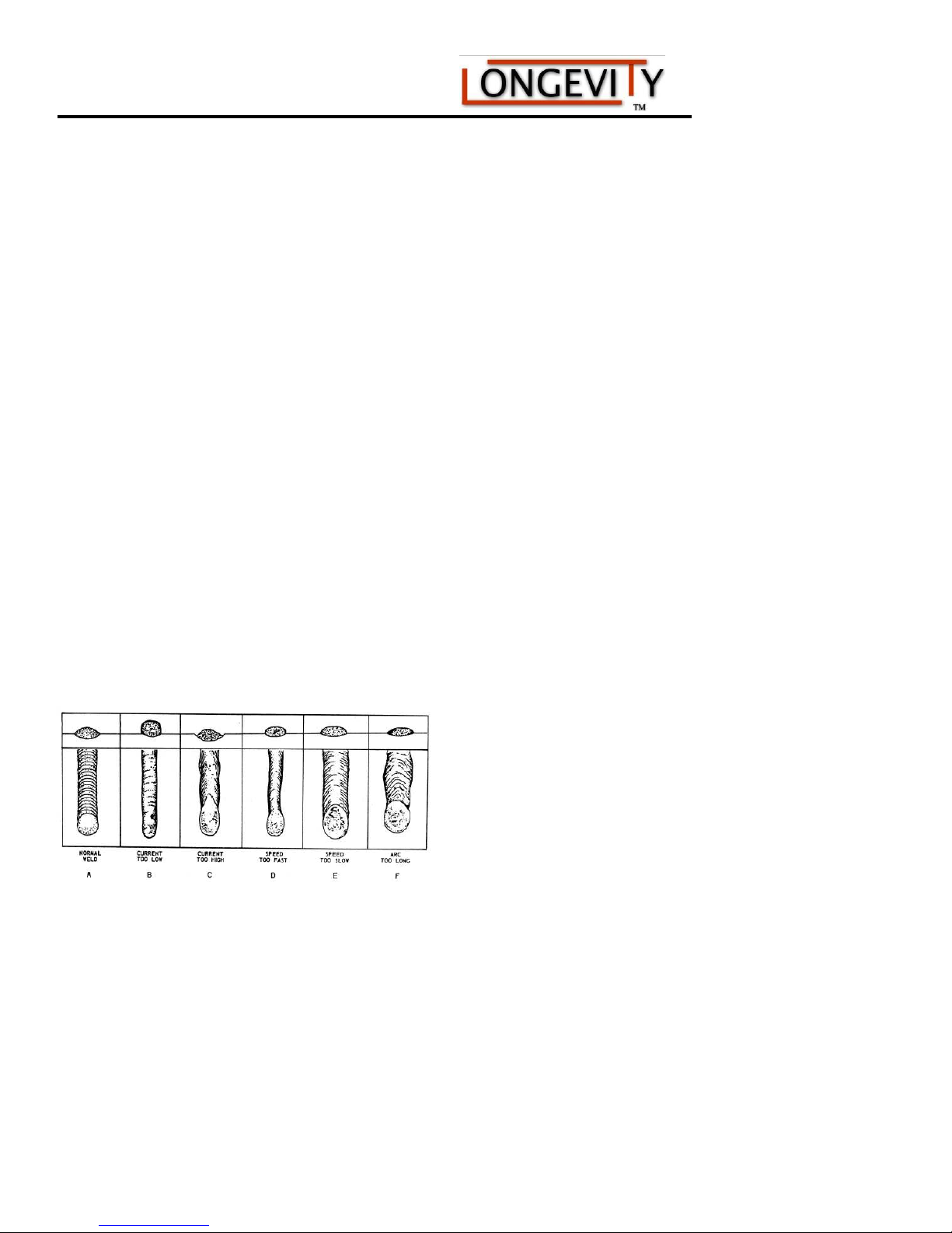
Basic Diagrams of Welding
Fig.1
Fig. 2
Figure 1: Comparison chart of welds
www.longevity-inc.com 31
Page 34
160/200/160P/200P AC/DC Series Machine
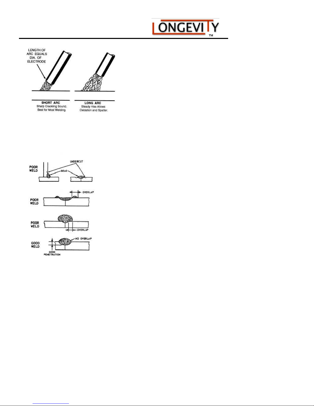
Length of Arc When an arc is too long, the metal melts off the
electrode in large globules and the arc may break frequently. This produces a wide, spattered, and irregular
deposit with insufficient fusion between the base metal and the weld. When an arc is too short, it fails to
generate enough heat to melt the base metal properly, causes the electrode
Fig. 3
produces uneven deposits with irregular ripples. The recommended length of the arc is equal to the diameter of
the bare end of the electrode, as shown in figure 3.
The length of the arc depends upon the type of electrode and the type of welding being done; therefore, for
smaller diameter electrodes, a shorter arc is necessary than for larger electrodes. Remember: the length of the
arc should be about equal to the diameter of the bare electrode except when welding in the vertical or overhead position. In either position, a shorter arc is desirable because it gives better control of the molten puddle
and prevents atmospherical impurities from entering the weld.
www.longevity-inc.com
Setting the length of an arc to stick frequently to the base metal, and
Page 35
160/200/160P/200P AC/DC Series Machine
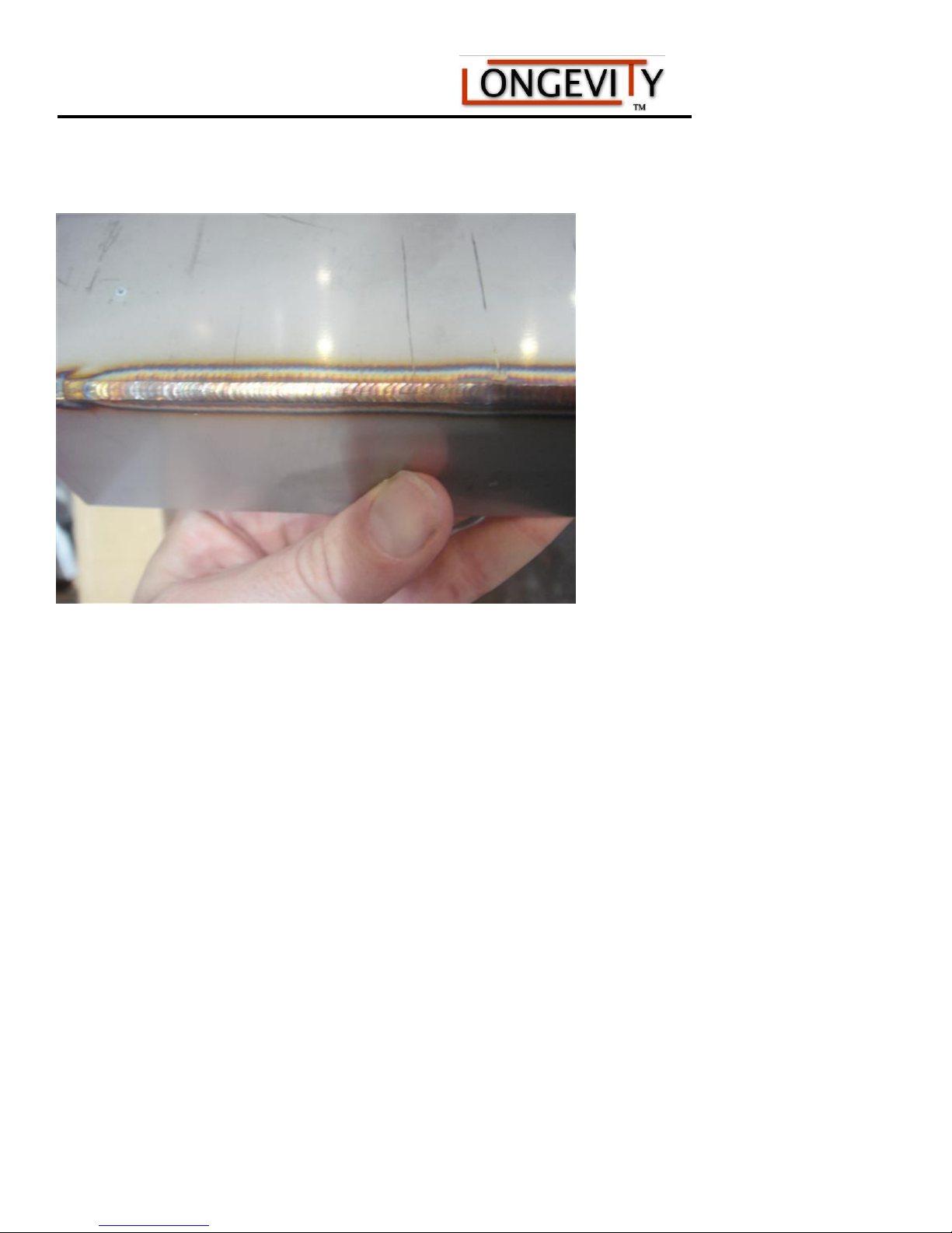
Sample of a quality stainless steel weld:
TALLATION
www.longevity-inc.com 33
Page 36

160/200/160P/200P AC/DC Series Machine
STICK/ARC Welding
Stick Welding
(Also known as MMA-Manual Metal Arc or Shielded Metal Arc Welding-SMAW)
Connect the Stick torch to the - terminal and Torch Control receptacles.
Connect the ground clamp to the + terminal and clamp the metal to be welded. Reverse the torch and ground
connections for DCEP (Direct Current Electrode Positive).
DC Stick - Select Stick, DC, desired amps using Base cur knob
1. Insert electrode into electrode holder. Position the electrode for the most comfortable position so that the
electrode can be held directly over the work piece with a slight angle.
2. Set Amperage to the recommended amperage by the electrode manufacturer. Strike an arc by swiping it briskly
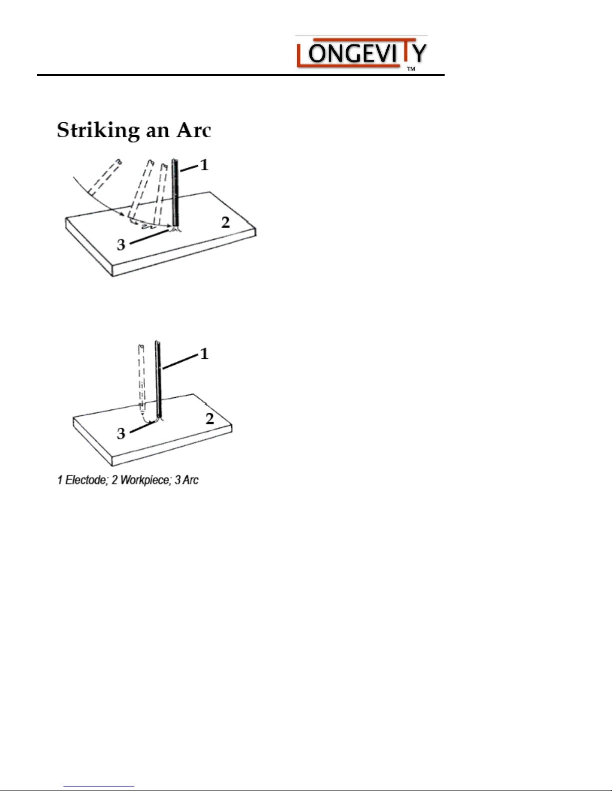
across the work piece in the same manner as one would strike a match. Alternatively, you may strike an arc with
firm tapping motion against the work piece. Either method is acceptable. An arc should initiate. Continue to keep
the arc going by holding the electrode off the work piece no more than the electrode width.
3. Continue the arc by feeding the electrode into the weld puddle while moving the electrode forward. This will
take some coordination, but will be fairly easy to do after practice. Do not allow the arc to become too long,
because air and slag can become entrapped in the metal. The sound of a proper arc will be similar to a gentle
frying sound. A long arc will emit a humming sound. An arc that is too short may be extinguished and the
electrode may stick to the work piece. If the electrode sticks, immediately release the electrode from the electrode
holder and break the electrode loose by hand. If the flux breaks off, simply trim off the excess rod until flux and
bare metal meet. A welding rod must have flux to shield the weld from the atmosphere or the weld will fail.
4. Use the Basic Current control to change arc qualities. Adjust the amperage according to the recommendations
of the electrode (welding rod) manufacturer for the type and size of the electrode used. When welding in the AC
mode the AC Frequency control will affect how crisp the arc is, whether it is smooth and buttery or deeply
penetrating. Use it to suit the desired weld finish. Experimentation will be required to find the optimal setting
desired. It is an excellent tool for out of position welding.
5. Electrode selection. Electrodes are usually given performance and characteristic ratings using a system of
letters and numbers determined by the American Welding Society (AWS). The rating system includes the
minimum tensile strength of the finished weld, the weld position (flat, vertical, horizontal, or overhead or a
combination of two or more positions) and the flux type. Additional information may be given. Each
manufacturer has their individual name and terminology as well. As there is no general recommendation that can
be made about a particular electrode selection, except for practice welds, a electrode designated by the AWS as E
6011, E 6013, E 7014, or E 7018 may be used, each having its own distinct features and purpose. These are
among the most common electrodes used in the industry and are not difficult to find. E 6011 electrodes are not as
smooth running as some of the other electrodes, but offer the advantage of being able to weld on rusty metal and
contaminated surfaces. It is widely used and requires very little skill to begin using. This is not a particular
www.longevity-inc.com
Page 37

160/200/160P/200P AC/DC Series Machine
endorsement of an E6011, rather a simple example of what may be used in developing proficient technique. It is
recommended that a variety of electrodes be used and practiced with. Consultation with an experienced local
welding supplier will help greatly in determining what welding electrode is the best for your given situation.
Many times, samples or small packages of electrodes are available at relatively low cost to determine for yourself
the best electrode to use.
Stick Electrode Chart Example: E 60 1 3
Strength
60--60,000 psi,
70--70,000 psi
Weld Position
1--All positions: Flat, Vertical, Horizontal, & Overhead
2--Flat Position or Horizontal Fillets Only
3--Flat Position Only
Weld Characteristics
0--Non-low hydrogen, DC Reverse polarity
1--Non-low hydrogen, AC or DC Reverse polarity
2--Non-low hydrogen, AC or DC Straight polarity
3--Non-low hydrogen, AC or DC Either polarity
4--Non-low hydrogen, iron powder coating, AC or DC Reverse polarity
5--Low-hydrogen, DC Reverse polarity
6--Low-hydrogen, AC or DC Reverse polarity
7--Non-low hydrogen, iron powder coating, AC or DC Reverse polarity
8--Low hydrogen, iron powder coating, AC or DC Reverse polarity
Polarity Definition
electrode negative =straight polarity (typical stock machine setup)
electrode positive = reverse polarity
Be sure to observe the electrode manufacturer recommendations regarding polarity. If the weld appears lumpy,
porous or otherwise malformed, change the polarity of the ground cable and the electrode holder cable. Many
electrodes run with in reverse polarity, (DCEP) setting. A few run with a straight polarity (DCEN). Some will run
either way. For reverse polarity (DCEP) stick welding, swap the electrode holder and ground cable connections.
Proper weld identification. Overlap and undercutting are two main causes of weld failure. Proper washing of the
weld bead into the sides or “toes” of the weld is important. Keep the welding electrode or the TIG tungsten and
welding arc within the weld joint to prevent overlap. Pausing on the sides of the welds to wait for the sides to fill
reduces the chance of undercutting, even if the current is a little too high. If it is possible, with any practice weld,
cut the joint down the middle, lengthwise, or place the weld in a vice and use a hammer to bend the metal over the
weld area until it is either broken or bent 90 degrees. This destructive testing method will help you improve your
skill by revealing faults and flaws in your welds.
www.longevity-inc.com 35
Page 38

160/200/160P/200P AC/DC Series Machine
Stick (SMAW)Electrode Welding
Stick, the most basic of welding processes, offers the easiest option for joining steel and other metals. Although
it produces the least pretties or cleanest welds, ARC/STICK welding gets the job done! Stick welding power
sources deliver inexpensive options for welding versatility, portability and reliability. Stick joins metals when
an arc is struck between the electrode and the work piece, creating a weld pool and depositing a consumable
metal electrode into the joint. The electrode's protective coating also acts as a shielding gas, protecting the weld
and ensuring its purity and strength. Best for windy conditions and adverse environments.
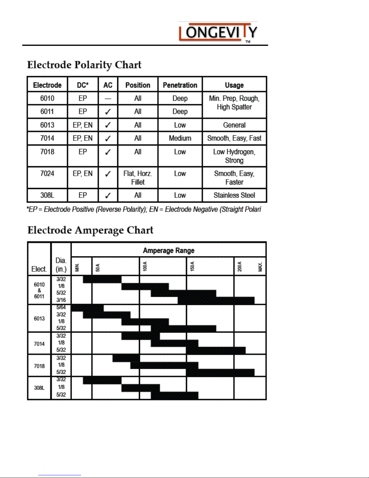
If you’re not familiar with Stick (SMAW) welding basics, the following information can make choosing
an electrode easier.
AWS
Class
E6010
E6011
E6013
E7014
E7018
E7018AC
Position
Polarity Usage
All DCEP
All AC,DCEP
All AC,DCEN,DCEP
All AC,DCEN,DCEP
All DCEP
All AC,DCEP
A great choice for welding on dirty, rusty, greasy or
painted steel - especially in vertical or overhead
applications.
All-purpose stick electrode; used for carbon and
galvanized steel; 60,000 PSI tensile strength; deep
penetration and ideal for welding light to medium
amounts of dirty, rusty or painted materials.
Light to medium penetrating all-purpose stick
electrode; for use on carbon steel; 60,000 PSI tensile
strength; good for general all-purpose applications
and joints with poor fit-up.
For higher-deposition requirements; 70,000 PSI
tensile strength; ideal for applications requiring light
penetration and faster travel speeds.
Low-hydrogen electrode; for low, medium and high-
carbon steels; 70,000 PSI tensile strength; ideal for
out-of-position welding and tacking; not
recommended for low-voltage AC Welders.
Low-hydrogen electrode; for low, medium and high-
carbon steels; 70,000 PSI tensile strength; ideal for
out-of-position welding and tacking; specially
formulated to operate with small 208/230 volt AC
welders.
www.longevity-inc.com
Page 39
160/200/160P/200P AC/DC Series Machine
www.longevity-inc.com 37
Page 40
160/200/160P/200P AC/DC Series Machine
Helpful Hints
Use a drag technique for most applications.
Take precautions with flying materials
when chipping slag.
Keep electrodes clean and dry - follow
manufacturers instructions.
Common steel electrodes (refer to chart
above).
Penetration: DCEN- Less penetration; AC
- Medium (can be more spatter also); DCEP Most penetration
Catalog and Capabilities
LONGEVITY has what you need for stick welding,
from welders to welding supplies and protective
clothing. Stick welders come in two basic
classifications; 115V stick welders and 230/460V
stick welders. Stick Electrodes or welding rod for
stick welding are available in stainless steel, carbon
steel, low alloy steel, maintenance alloy, hard facing,
nickel alloy, and magnesium
www.longevity-inc.com
Page 41

160/200/160P/200P AC/DC Series Machine
Routine Maintenance
The life of your machine and the quality of the work performed using your machine, will be enhanced by
practicing periodic routine maintenance.
At regular intervals, clear dust that may accumulate in the machine using clean and dry compressed air.
If the working condition has heavy smoke and pollution, the welding machine should be cleaned once a month.
Keep the machine exterior clean with mild soap and water.
Do not walk on or store items on the cables or cords.
Do not jar, drop, or stack items on top of the machine.
Always connect the machine to a well grounded electrical outlet.
Always check the torch consumables before and after use and ensure that they are clear of obstructions,
and that no parts are damaged.
Replace any worn or damaged consumables before using machine.
For periods of prolonged non-use, remove cables and store them in their original boxes in a cool dry
place, free of bug infestation.
www.longevity-inc.com 39
Page 42
160/200/160P/200P AC/DC Series Machine
Problems, Causes, and Solutions
Troubleshooting
If your unit is not properly functioning, please call us immediately toll free at 1-877-566-4462 for support. We
have included a small table here to diagnose most common problems.
Problems
Machine will not
turn on.
The machine runs,
but nothing is
happening
Arc will not start
Consumables
(tips) are being
consumed
Heavy Underside
Slag (Cutting)
Poor Cut Quality
Inconsistent
Arc
O.C. Over
Current LED
Lights
Issue Not Listed
Unit Will Not
Weld
Tungsten is
Melting or Being
Consumed
Quickly
Contaminated
Tungsten
Poor Weld Quality
www.longevity-inc.com
Check cords and breaker. If nothing is found, contact
LONGEVITY
Check to see if you are in the right mode, plasma cutter, tig,
stick. Check the torches and your ground. Make sure there is argon
or compressed air for plasma and tig.
Check the ground connection. Check the torch for proper
consumables installation. Replace consumables.
Improper air/gas flow. Increase the PSI on the regulator, check
for leaks in the hose, maintain a distance of 1/8” from the torch tip
or workpiece
Slow travel speed. Increase travel speed or amperage on unit.
Check Air Pressure. Insure your unit is capable of cutting the
desired thickness of material. Check the consumables to insure they
are producing a stable arc. Replace Consumables and insure you
have the proper PSI at the regulator.
Improper grounding or possible lack of air pressure. Check and
replace consumables and adjust the regulator to proper PSI
The unit has reached its DUTY Cycle. Leave power of the
machine on and allow fans to cool the machine. You can also turn
the machine off to properly cool it. Do not continue to weld until
light is off.
Contact LONGEVITY Toll Free 1-877-566-4462 or via email at
Check ground connection, torch setup, and check if you are in
the proper mode ARC/TIG. If you are TIG Welding check to see if
you have the proper TUNGSTEN and FILLER ROD.
Low Argon Gas flow. Check the Argon Gas flow. Turn up post
flow. Incorrect Tungsten or Incorrect Tungsten Size. Possible
small size shield cup. Read selecting the right tungsten on
www.longevity-inc.com/resources
If the Tungsten is dipping or melting inside the weld. Use
larger tungsten and fewer amps on the unit. Sharpen tungsten.
Remember to clean welding material prior to welding with
acetone. Practice on the form and technique. Use the right tungsten
and filler rod.
Causes/
Solutions
Page 43

160/200/160P/200P AC/DC Series Machine
Problems, Causes, and Solutions
Problems
STICK Welder
Having a Hard
Time Striking an
Arc
STICK Welder
Producing Poor
Quality Welds
Causes/
Solutions
Check the ground. Check the workpiece and clean it. Increase
the Arc Force on the unit.
Use the proper rod and polarity.
www.longevity-inc.com 41
 Loading...