

Page 1

Operating Manual
For
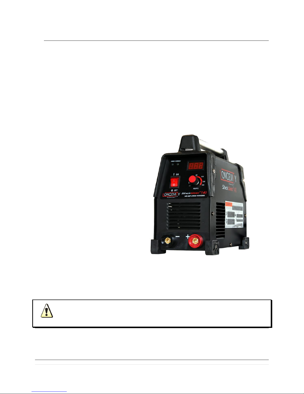
STICKWELD 140 110v/220v DC ARC WELDER
Page 2

Table of Contents:
PG. 3: Thank you From LONGEVITY
PG. 4-5: Warranty/Shipping Damage/Order Information
PG. 6-8: Warning and Safety Information
PG. 9: General Description
PG. 10: What’s Included
PG. 11: Specifications and Ratings
PG. 12: Installation Instructions
PG. 13-15: Operating Instructions and Stick Classification Chart
PG. 16: Front Panel
PG. 17-19: Stick Welding Tips
PG. 20-21: Maintenance and Troubleshooting
PG. 22: THANK YOU! Enjoy your new welding machine from LONGEVITY!
1 | P a g e
Page 3

THANK YOU!
We, at LONGEVITY, want to thank you for purchasing our product. You are almost ready to
experience Longevity Welding first hand. Longevity definitely appreciates your business and
understand that this equipment may be overwhelming to setup and operate so we have prepared a
manual that will assist you in understand your new plasma cutter/welder. If you have any
questions during or after reading this manual, please feel to contact us! Please take a moment
to register your product on our website at www.longevity-inc.com or www.lweld.com
Once again, thank you for choosing Longevity as your main welding supplier!
Longevity Global, Inc.
23591 Foley St
Hayward, CA 94545
Toll-Free Customer Support: 1-877-LONG-INC / 1-877-566-4462
Website: www.longevity-inc.com
Sales: [email protected]
Customer Service: [email protected]
Dealers: [email protected]
Complaints: [email protected]
Please join our welding forums to share welding tips and tricks, to receive useful information
from customers who also use our products, and to be a part of the Longevity™ welding
community at www.freeweldingforum.com
2 | P a g e
Page 4

W
arranty
LONGEVITY Plasma Cutters, Welders, and Multi-Purpose Welders are covered for specific
Parts and Labor warranty at our facility. For detailed information regarding your specific
LONGEVITY welder or cutter, please view our Terms and Policies page on our website at the
following website link: http://www.longevity-inc.com/terms/
Shipping Damage
Your machine is insured against damage during shipping. Keep all packing materials and
containers in case machine must be returned. We will initiate a claim with the shipping company
to cover damage or loss. If there is shipping damage upon opening your package, our customer
service team will work with you to get the matter resolved.
3 | P a g e
Page 5

In Warranty Service
Customers, who own machines that are in warranty and require service, should contact our
Warranty Department by email at [email protected] to obtain a return authorization code.
In addition to the warranty we offer, we would like for you to register your product on our
website at www.longevity-inc.com/resources. Remember, warranty starts from the date of
purchase. For your convenience, write your order information below so you can track your order
in case you need warranty work.
Order No.: _________________________________
Date of Purchase: _____________________________
Warranty Period: ______________________________
Out-of-Warranty Service
Customers, who own machines that are out of warranty and require service, should contact us for
an estimate. Longevity offers an exchange program on out of warranty units. We also help non
LONGEVITY customers with repairs, replacement, and service.
If your unit is not manufactured by Longevity and you cannot receive service from your
manufacturer or seller, Longevity will lend out hand. Our warranty policy is also available for all
plasma cutters and welders. For more information, please email us at [email protected]
4 | P a g e
Page 6
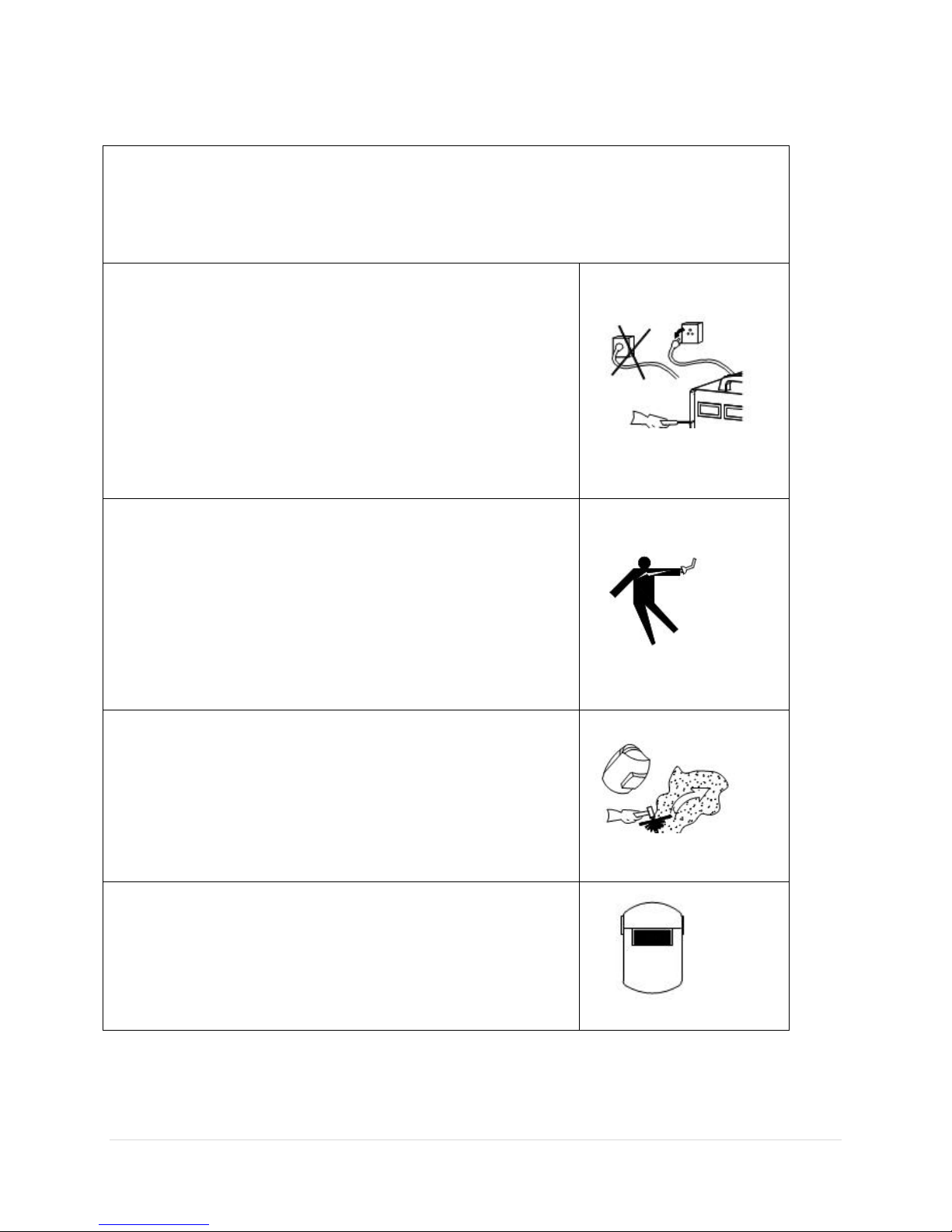
Welding and plasma cutting may be dangerous to the operator and to bystanders, if the
equipment is not operated properly. Welding or cutting must be performed in accordance with
all relevant safety regulations. Carefully read and understand this instruction manual before
installing and operating this equipment.
Changing function modes during welding may damage
equipment.
Before welding, disconnect the electrode-holder cable from the
equipment.
A circuit breaker is required to prevent electrical overload of the
equipment.
Only high quality welding tools should be used.
Electric Shock can be fatal.
Ensure that ground cable is connected in accordance with
applicable safety codes.
Never touch electrodes, wires, or circuit components with bare
hands. Wear dry welding gloves when welding.
The operator must be insulated from the work piece.
Smoke and gas can be harmful to health.
Ensure that the working area is well ventilated.
Avoid breathing smoke and gas generated during the welding
process. Cutting and welding can cause cancer because of the
smoke that comes from the welds and cuts.
Arc-light emission can be harmful to eyes and skin.
Always wear a welding helmet, anti-radiation glass, and work
clothes while welding.
Ensure that people in or near the working area are protected.
Warnings and Safety
5 | P a g e
Page 7
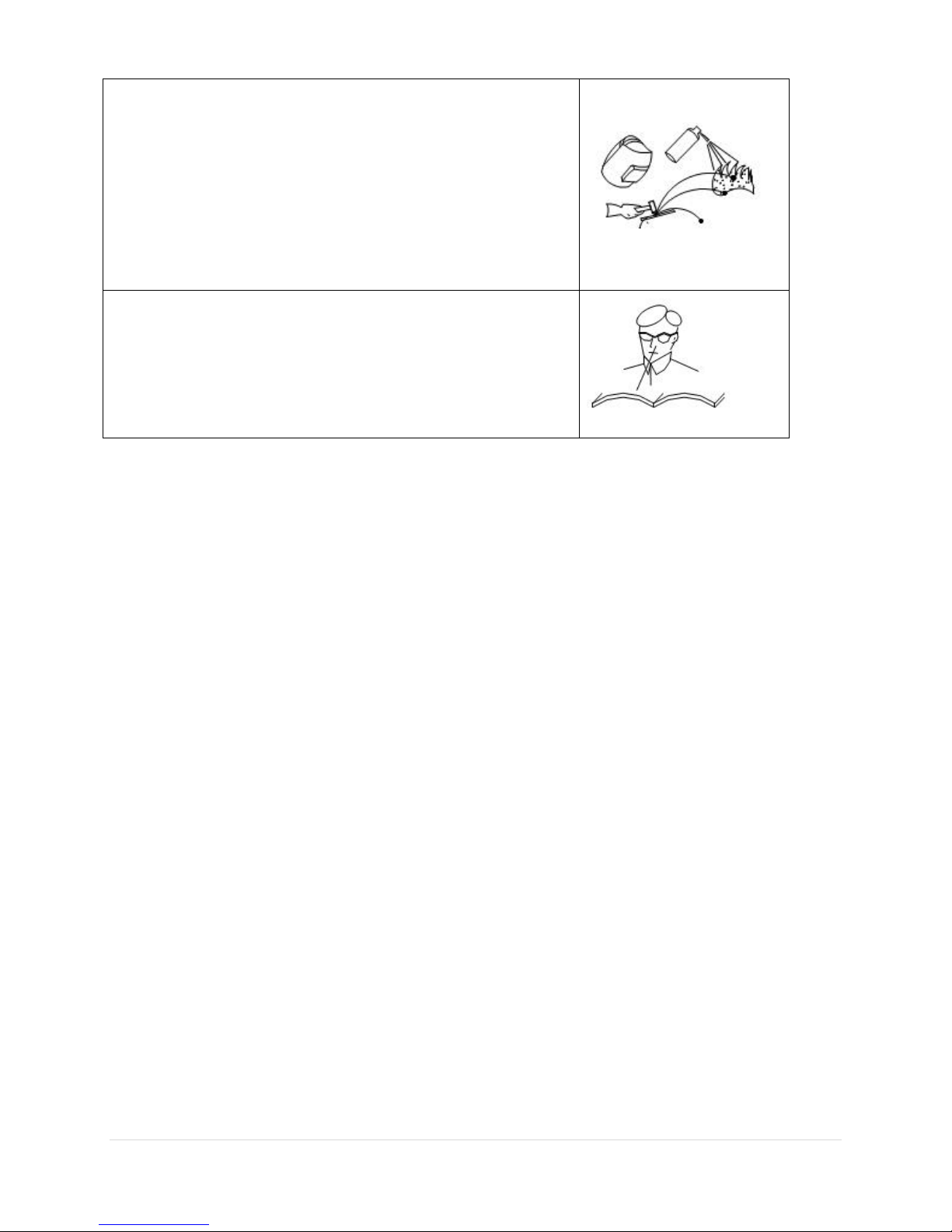
Welding splash is a fire hazard.
Keep flammable material away from the work place.
Keep a fire extinguisher nearby, and have all personnel trained in
its use.
Surface noise generated while welding or cutting can be harmful
to hearing.
In the event of a machine fault.
Refer to this instruction manual.
If the fault cannot be determined, contact your local dealer or
supplier for assistance.
6 | P a g e
Page 8

Safety Tips
Consider the following tips to ensure safe operation of your welding/cutting equipment:
Ensure that this welding equipment is installed in an area free of corrosive chemical gases,
flammable gases or materials, and explosive chemicals.
The area should contain little dust, and have a humidity of no more than 80%.
Operate the welding equipment in an area sheltered from direct sunlight and precipitation.
Work area temperature should be maintained at - to
If, because of an overload, the machine suddenly stops, and it is necessary to restart it, leave
the internal fan operating to lower the inside temperature.
Always wear protective clothing and a welding mask to protect your skin.
Wear safety goggles designed to darken the arc generated by your machine.
Wear suitable noise protection to protect your hearing.
Ensure that machine is grounded through the power cord or on the machine case.
Never operate the machine in bare feet or on a wet floor.
Never switch the machine off while it’s in use. Doing so will damage the internal circuitry.
Ensure that your circuit breaker is rated to handle the current requirements of your machine.
Use a UL approved receptacles and plugs with your machine. Never hard wire the machine to
main power.
Work in a well-ventilated area to avoid smoke. Keep your head out of the smoke. Ensure that
air is flowing away from you to avoid inhaling smoke.
Ensure proper ventilation through the machine’s louvers. Maintain a distance of at
least
12 inches between this cutting equipment and any other objects in the work area.
Use a screen or curtain designed to keep passer byes from viewing the arc.
The arc spray and metal spray from machine use may cause nearby fires. Use caution.
If, after reviewing this manual, you have any problems in setting up or operating your
machine, contact us at [email protected].
7 | P a g e
Page 9

General Description:
StickWeld™ Series 140AMP Ultra-Portable Arc/Stick/MMA Welder is one of the lightest arc
welders on the market at this time weighing in at only 13lbs! This DC stick welder comes with
everything that you will need to operate this machine except for welding rods and a power
supply. This machine is powered by a high speed cooling fan that will keep this welding machine
running longer and cooler than any other welder machine out there on the market. This machine
is the ultimate in portability! StickWeld comes with its own suitcase, making traveling from job
site to job site simple and easy. An Auto Darkening Welding Helmet is essential for this kind of
welding as it would be for all welding and cutting. Please check out some of the welding helmets
that we carry for some great deals and savings. This machine can also operate on either 110v or
220v input power and it comes with an easy to convert power plug. At 110v, you are still
pushing an impressive 140 amps of power.
8 | P a g e
Page 10
Model
Parameters
STICKWELD 140
Power voltage(V)
110V±15%
220V15%
Frequency (Hz)
50/60
Rated input current
(A)
55.8
27.9
No-load voltage(V)
50~80
Output current(A)
30-140
Rated output
voltage(V)
25.6
Duty cycle (%)
60 @ 140amps
No-load loss(W)
40
Efficiency
80
Power factor
0.73
Insulation grade
F
Housing protection
grade
IP21
Weight(kg)
9
Dimensions(mm)
415×280×330
Specifications and Parameters:
9 | P a g e
Page 11
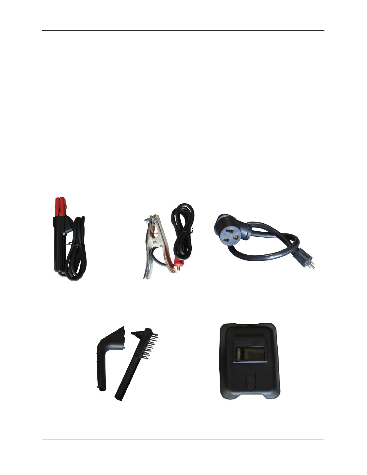
Included Accessories:
StickWeld 140 Inverter based welder
300AMP rated stick holder (6ft)
300AMP rated Ground Clamp (6ft)
110v/220v Power Plug Adapter
Chipping Hammer and Steel Brush
Welding Mask
10 | P a g e
Page 12
INSTALLATION INSTRUCTIONS
The machine is equipped with power voltage compensation equipment. When the power voltage
fluctuation is between ±15% of rated voltage, it will operate normally.
If you are planning on increasing the length of your power cable, please insure you use an adequate
gauge cable such as a 4 or 6 gauge to insure there is enough power for the machine.
1. Make sure the fan is not blocked in the rear to avoid damage and over heating.
2. There is a grounding lug on the back of the machine if you are using a grounding cable that is longer than six (6)
meters. Use the grounding lug in that situation.
3. Correctly connect the Stick Holder to the
machine on the positive (+) end for straight
polarity and turn clockwise to lock in the
DIN connector. You can also reverse
polarity by switching the Stick Holder to
negative.
4. Connect the Ground Clamp to Negative (-)
for straight polarity. You can also reverse
the polarity depending on the welding
situation.
5. With Arc or Stick Welding, you are able
to reverse polarity when DC Stick
Welding. By using the wrong polarity
you may have an unstable arc. Please
make sure that you firstly try welding
with the Stick Holder in the Positive (+)
position and the Ground Clamp in the
Negative (-) position.
6. Please check your input voltage and connect the machine using the supplier 220v to 110v converter if
you are connecting to 110v power or connect straight to a 220v power supply. Please make sure your
plug is within the allowed parameters of the allowed voltage.
If the distance of the work cable and ground cable is 50-100ft, please upgrade the
thickness of the cables to insure a good arc and connectivity. We recommend a thick gauge.
11 | P a g e
Page 13

Specification
of Diameter
in MM
φ2.5
φ3.2
φ4.0
φ5.0
Current
70-100A
110-140A
170-220A
230-280A
Stick
Welding
Covered Electrodes for SMAW of Carbon Steel per AWS A5.1
Arc-Welding Processes - SMAW
Classification
Covering
Weld
Position
Current
Characteristics, applications
E6010
High-cellulose
sodium
F, V,
O, H
dcep
A general purpose electrode for
joining of carbon steel.
Deep-penetrating forceful arc.
Thin slag. Us in all positions,
single and multiple pass, plate
and pipe, galvanized and alloy
steels. Ships, bridges, buildings,
piping, tanks, pressure-vessel
fittings.
E6011
High-cellulose
potassium
F, V,
O, H
ac, dcep
Similar to E6010, but for use
with ac. Dcep gives reduced
penetration.
E6012
High-titania
sodium
F, V,
O, H
ac, dcen
Dense slag that covers the bead,
low-penetrating arc. Use to
bridge joints with poor fitup.
Fillets have smooth convex
face. Runs well at amps higher
OPERATING INSTRUCTIONS
1. Turn on the power switch, the digital display will show amps, and the cooling fan will begin to
start turning.
2. Adjust knob of the desired welding current ranging from 30-140amps.
3. A general welding current chart is provided below:
4. Here is a Stick Welding Classification Chart:
12 | P a g e
Page 14

than E6010/E6011.
E6013
High-titania
potassium
F, V,
O, H
ac,
dcen,
dcep
Similar to E6012; quieter arc,
smoother bead, cleaner weld
metal, fewer inclusions
Characteristics vary with
supplier. Run at lower current
than for E6012.
E6022
High iron
oxide
F
ac,
dcep,
dcen
Use for single-pass,
high-current, high-speed
welding of groove welds in flat
position horizontal lap joints
and fillet welds in sheet metal.
E6027
High iron
oxide,
iron powder
H-fillets,
F
ac, dcep
For fillet of groove welds, flat
position, heavy slag, good
sidewall fusion. Use at high
amperages on thick plate.
E7014
Iron powder,
titania
F, V,
O, H
ac, dcep
Iron powder boosts deposition
rate and efficiency. Use at high
amperages on carbon and
low-alloy steels.
Low-penetrating arc, use to
bridge poor fitups. Smooth,
fine-rippled bead, convex
fillets.
E7018,
7018-1
7018R
7018-1R
7018H16, H8,
H4
Low-hydrogen
potassium,
iron powder
F, V,
O, H
ac, dcep
Iron-powder addition increases
deposition rate. Use on carbon,
high-carbon, and low-alloy
steels. Smooth arc, low spatter.
Flat and horizontal welds are
finely rippled. Convex. Other
types: E7018-1H16R,
E7018-1H8R, E7018-1H4R.
E7018M
Low-hydrogen
iron powder
F, V,
O, H
dcep
Yield strength, 53,000-72,000
lb/in. Ductility high, extra
impact strength and
compositional limits and limits
on moisture and hydrogen.
Similar to E7018-1H4R,
13 | P a g e
Page 15

MIL-7018-M. Characteristics
similar to E7018.
E7024
E7024-1
Iron powder,
titania
H-fillets,
F
ac,
dcep,
dcen
Iron powder for high deposition
rate, high travel speed, flat,
smooth fillets, finely rippled.
Smooth, quiet arc, low
penetration. E7024-1 deposits
more-ductile weld metal of
improved Charpy values.
WARNING!
Before operating the machine, please make sure the machine power switch is in
the off position. Make sure all cables are connected firmly. Power the machine on after
checking reading all of the safety guides.
14 | P a g e
Page 16
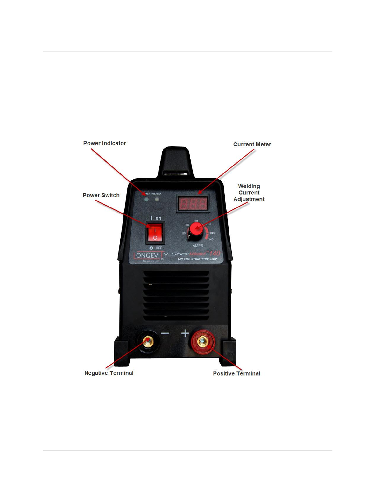
STICKWELD 140 FRONT PANEL:
The panel picture above is for reference only. If any difference with the real machine, please follow
with the real machine.
15 | P a g e
Page 17

Arc welders don't have a button to start the arc. Unlike MIG welders the rod (electrode) will
become live as soon as the machine is switched on.
The arc is started by touching the electrode momentarily against the work to complete the
electrical circuit before raising the electrode to establish the arc. This needs to happen
quickly to avoid welding the rod to the work. "Tap Starting" and "Scratch Starting" are the
two common methods of starting the arc.
Because the rod is live at all times it needs to be kept insulated from the earth when not in
use. In the photo the welding bench is earthed, and a piece of wood is being used to isolate
the rod from the bench. After welding the rod is returned to the piece of wood.
Tap Starting
A sharp tap of the rod against the work will remove excess flux from the end of the rod and
create the electrical contact needed to start the arc.
A sharp wrist action should allow a momentary contact with the work before quickly pulling
the rod a short distance away. Too heavy a contact or too slow an action can cause the rod
to stick.
In the video the auto-darkening helmet darkens as soon as the arc is started. The light is
bright at first because the arc length is initially too long. The arc length is quickly reduced
to the correct distance for welding.
Rods start much more easily on the second attempt. It is good practice to first start the arc
on some scrap material before starting the arc at the beginning of a weld.
Scratch Starting
An alternative starting method is to lightly scratch the rod against the work. Moving the rod
against the work removes excess flux from the rod and allows electrical contact from the
steel in the middle. As soon as the rod starts to spark it is lifted from the work to start the
arc.
In the video a backwards and forwards scratching motion is used to remove the flux
coating. A limited movement should mean the arc will start somewhere close to where you
want to start welding. When the first spark is seen the rod is pulled away from the work to
prevent sticking, and then it is returned to the normal arc length for welding.
The scratch start technique is more prone to sticking as it relies on human reaction times.
It can be a useful technique for difficult to start rods, or for AC machines and those with
low open circuit voltage which make Tap Starting more difficult.
Excessive pressure on the rod while scratching will increase it's chances of sticking.
STICK WELDING TIPS
16 | P a g e
Page 18

Rods Sticking to the Work
If you are new to arc welding you will frequently stick the rod to the work when trying to
start the arc. The rod welds itself to the work and it won't be possible to remove it just by
pulling. Moving the rod backwards and forwards, or twisting the rod should fatigue the joint
allowing you to remove the rod. If you have a crocodile clip type electrode holder you can
just release the rod from the holder.
There's no need to panic when the rod sticks. It's normal for rods to stick occasionally, so
arc welders are designed to cope with it for a short time. Inverter welders will reduce
voltage automatically, and transformer welders should only go up in smoke if the rod is
stuck for a prolonged period.
For interest, the photo shows the electrode of a 7018 rod recessed into the flux coating
after welding - it illustrates why the flux coating needs to be removed before the arc will
start.
A tip to make starting much easier
Keep some scrap material near the work and start the rod on that before beginning your
weld. This will remove excess flux and warm up the rod which will make it much easier to
start your weld.
Learning to Arc Weld - Basic Technique
Arc welding takes some effort to learn, and it is very sensitive to the position of the work.
It's a good idea to keep things easy to begin with by laying beads on the flat. We'll cover
joints later.
The following setup is a good starting point for this tutorial:
scale than other electric welding processes, but it is good practice to clean the worst off
with a grinder before welding.
learn with DIY store rods had terrible trouble until someone sent him a few brand name
rods to prove a point. Also 3.2mm rods are easier to learn with than 2.5mm rods.
amps - the current is determined more by the rod size than the thickness of sheet).
used in TIG). Use AC if that's all you have.
Rod Angle (lead angle)
For welding on the flat the rod should be angled 10 to 20 degrees from vertical and pulled
in the direction of the arrow. The angle of the rod prevents the slag overtaking the rod
17 | P a g e
Page 19

(welding over slag would cause inclusions in the weld).
In the photograph the rod has been bent at the electrode holder to position the holder at a
more comfortable angle.
It's OK to support the top of the electrode with your spare hand and this improves control
of the electrode. Electric shocks aren't a problem, but be careful to reposition your hand
away from the heat before the electrode gets too short.
Arc Length
The arc length is the distance between the electrode and the weld pool. It should be
roughly the same as the diameter of the rod.
This is nowhere near as straightforward as it sounds!
To achieve the correct arc length using 3.2mm rods the distance between the flux coating
on the rod and the flux on top of the weld might be less than 1mm.
The arc length is normally judged by the sound and visible light from the arc.
In the video the arc length is varied between correct, too long, and too short. Both the
intensity of light and the sound of the weld alter dramatically with the length of the arc.
The arc should be kept short and hide the majority of the light from the weld without
pushing the rod into the slag pool. A good short arc length will result in a consistent sharp
crackling sound.
Maintaining Lead Angle and Arc Length
The rod becomes shorter as the weld progresses, and it takes a conscious effort to reduce
the length of the arc as the rod gets shorter. Excess arc length can lead to an unstable arc,
excess heat and undercutting and is probably the most common beginner fault.
The angle of the rod should also be maintained over the length of the weld. A little practice
is required to avoid decreasing the lead angle as the weld progresses, as this can result in
slag inclusions and even cause the arc to stall. The easy way to maintain rod angle is to
focus attention on moving the rod holder rather than the rod as the weld progresses.
Welding Motion
For most arc welding the rod is moved in a straight line to form a "stringer". A tiny amount
18 | P a g e
Page 20

of weave can be used to help control speed and direction.
In the video the arc is started with a tap start. The rod quickly becomes shorter as the weld
progresses and the motion that can be seen is constant correction to maintain a short arc
length.
Note the rod angle is also maintained. It takes practice to maintain arc length and rod
angle, especially if you are moving to arc welding from another welding process.
Slag
Don't look closely at a hot weld - bits of slag continuously ping off the weld as it cools and
it is very painful to have them removed after they'
19 | P a g e
Page 21

NOTES AND PREVENTIVE MEASURES
1. Environment
1) The machine should be operated in dry environments.
2) Ambient temperature should be between -10 to 40 degrees centigrade.
3) Avoid welding in high temperature climates. Avoid water damage or water intrusion.
4) Avoid welding in dusty areas or salty water environments where there is a chance of corrosion.
5) Avoid gas welding in environments with strong airflow.
MAINTENANCE
1. Remove dust by dry and clean compressed air regularly to avoid build up on the mother boards.
Use dry compressed air to remove particles that may have deposited during operation in harsh
environments.
2. Pressure of compressed air must be within the reasonable range in order to prevent damaging to
small components of inner-machine. We recommend using a dust can and not an air
compressor.
3. Check internal circuit of welding machine regularly and make sure the circuit connections are
connected correctly and tightly (especially plug-in connector and components). If rust is found,
please clean it, and connect again tightly.
4. Prevent water and steam from entering into the machine. If that happens, please blow it dry and
check insulation of machine. Make sure the machine is dry before operating.
5. If welding machine will not be used for long time, it must be kept with a cover in a dry and clean
environment to avoid corrosion.
20 | P a g e
Page 22

Faults symptom
Solutions
Power indicator is not lit,
fan is not working, no
welding output.
A. Make sure power switch is connected properly.
B. Make sure your power plug is connector to the proper voltage.
Power indicator is lit, fan
doesn’t work, no welding
output.
A. Check the input power to make sure you are connected to the proper
power level – either 110v or 220v
B. Dirty or Unstable power is detected and the machine has entered a fail
safe mode. Unplug and restart the machines after 5 minutes once the
voltage is stable.
C. Restart the machine but unplugging the power cable and turning the
machine on in 5 minutes
D. Cables in the power plug or the machine power switch are loose or not
connected firmly.
ARC Welding Current
Knobs is Erratic
A. Amp Adjustment Knobs needs replacement along with potentiometer.
B. Terminal of output has a broken circuit or poor connection.
Fan is working and
abnormal indicator is not
lit, no welding output.
A. Check if components are connected properly.
B. Check if the output terminals are connected properly.
C. If there are questions about the mother board, contact the authorized repair
center.
Fan is working and
abnormal indicator is lit,
no welding output.
A. Overload current protection may start, please turn off machine first, then
restart it after abnormal indicator is off.
B. Overheat protection may start, it will become normal in 2-3min.
C. Inverter circuit may go wrong. Please disconnect the power supply plug of
the main transformer on MOS board (near fan VH-07), then restart the
machine.
1) If abnormal indicator is still lit, that means some fieldistors on MOS
board are damaged. check and replace them.
2) If abnormal indicator is off:
a. Maybe transformer of middle board is damaged, measure primary
inductance value and Q value of main transformer by inductance
bridge.
b. Primary value is parallel circuit, L=1.2-2.0mH, Q>40 If inductance
value and Q value is low, replace it.
c. Maybe some of secondary rectifier tube of transformer is broken,
check and replace rectifier tube.
D. Maybe feedback circuit is in fault.
Power supply
(1phase ~ 220V)
Electrode holder
Earth clamp
LONGEVITY® Global, Inc. thanks you for your purchase and the opportunity to be able to serve you. If,
after reviewing this manual, you have any problems in setting up or operating your machine, contact us
21 | P a g e
Page 23

LONGEVITY® Global, Inc.
Toll-Free 1-877-LONG-INC / 1-877-566-4462
Website: www.longevity-inc.com
Sales: [email protected]
Customer Service: [email protected]
Dealers: [email protected]
Please join our welding forums to share welding tips and tricks, to receive useful information from
customers who also use our products, and to be a part of the LONGEVITY® welding community at
www.freeweldingforum.com
For the coolest LONGEVITY sponsored race teams plus a complete racing forum that covers everything
from Drag Racing to RC Car Racing, please check out www.longevity-racing.com!
Enjoy your new welding machine from LONGEVITY! Thanks again!
22 | P a g e
 Loading...