

Page 1

SpoolGun 140 compatible with the MigWeld 140
Operating Manual
For
SpoolGun 140
Spool Gun compatible with the MigWeld 140
1 | P a g e
Page 2

SpoolGun 140 compatible with the MigWeld 140
Table of Contents:
PG. 3: Thank you From LONGEVITY
PG. 4-6: Warranty/Shipping Damage/Order Information
PG. 7-9: Warning and Safety Information
PG. 10: Specifications
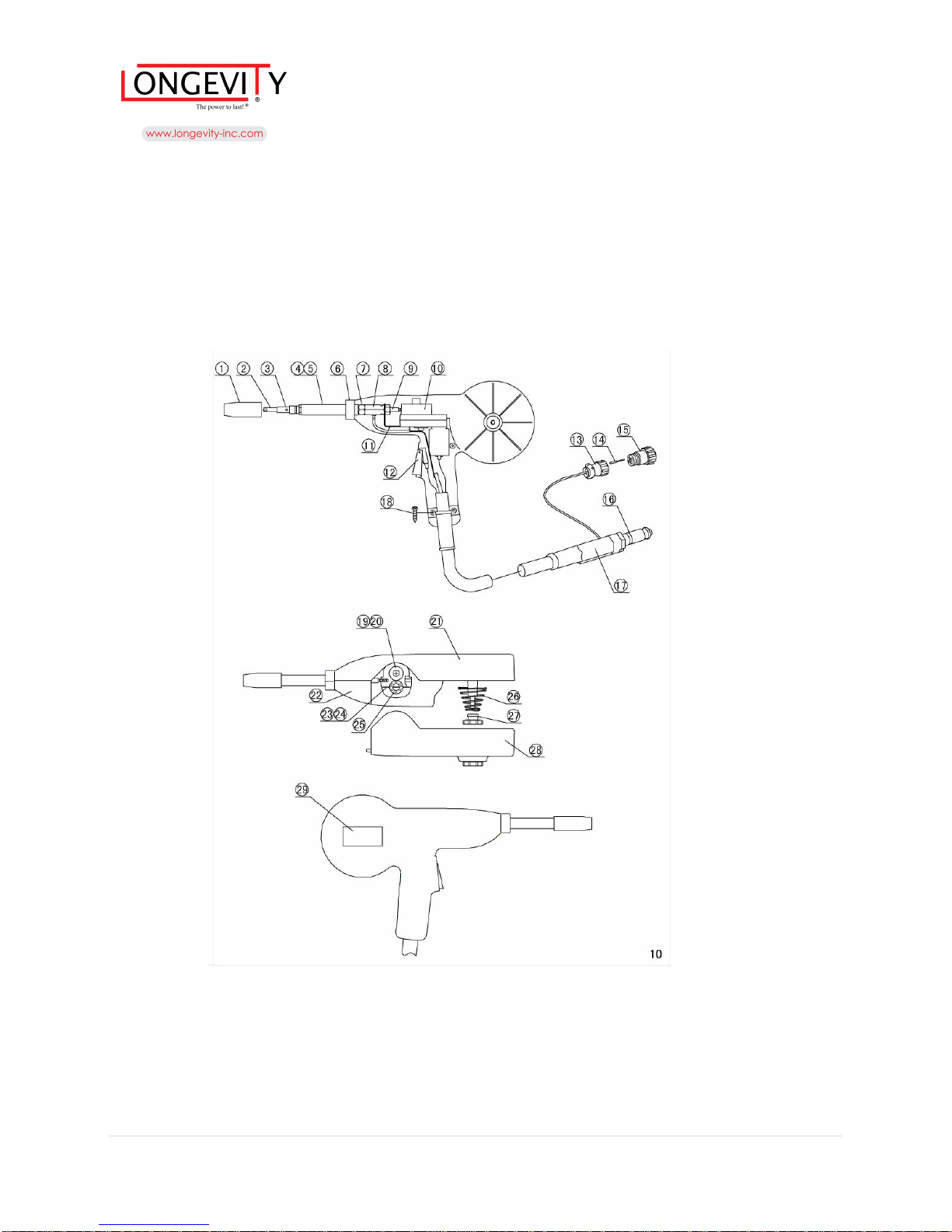
PG. 11-12: Parts List
PG. 13: Voltage Settings
PG. 14: Loading Aluminum Wire
PG. 15: Components and Controls
PG. 16: P6 Connector Pin-out
PG. 17: Enjoy your new welding accessory from LONGEVITY!
2 | P a g e
Page 3

SpoolGun 140 compatible with the MigWeld 140
THANK YOU!
We, at LONGEVITY, want to thank you for purchasing our product. You are almost ready to
experience Longevity Welding first hand. Longevity definitely appreciates your business and
understand that this equipment may be overwhelming to setup and operate so we have prepared a
manual that will assist you in understand your new plasma cutter/welder. If you have any
questions during or after reading this manual, please feel to contact us! Please take a moment to
register your product on our website at www.longevity-inc.com or www.lweld.com
Once again, thank you for choosing Longevity as your main welding supplier!
Longevity Global, Inc.
23591 Foley St
Hayward, CA 94545
3 | P a g e
Page 4

SpoolGun 140 compatible with the MigWeld 140
Toll-Free Customer Support: 1-877-LONG-INC / 1-877-566-4462
Website: www.longevity-inc.com
Complaints: [email protected]
Please join our welding forums to share welding tips and tricks, to receive useful information
from customers who also use our products, and to be a part of the Longevity™ welding
community at www.freeweldingforum.com
Check out LONGEVITY Racing at www.longevity-racing.com
4 | P a g e
Page 5

SpoolGun 140 compatible with the MigWeld 140
Warranty
A manufacturer's limited warranty covers parts only, unless indicated below, and is furnished for
five years from the date of purchase warranting the product to be free of material defect or
workmanship as follows:
Plasma Cutters, Welders, and Multi-Purpose Welders (Coverage for Parts and Labor for five
years from the purchase date at our facility).
In the event of product failure or malfunction, the purchaser/recipient must contact
LONGEVITY™ GLOBAL, INC. to obtain an RMA (return or missing) number and a location of
a designated repair facility. The welder, plasma cutter, multi-purpose unit, or any other welding
related equipment comes with warranty on all internal components. The torch, cables, power
cord, clamps, air regulator, argon regulator, hoses, case, paint, and consumables are not covered
under warranty. Packages that are not pre-approved for return, and that do not have an RMA
number will be refused and returned to the purchaser/recipient at the purchasers/recipients own
cost. The product must be returned in its original packaging, with all accompanying components.
Repair or replacement of the defective product will be at our option. The repaired/replaced
product will then be returned to the purchaser. LONGEVITY Global, Inc. will cover the return
and replacement shipping charges (both ways) for units in need of warranty within and only for
the first 30 days from the purchase date. After the 30 days from the purchase date, the purchaser
shall be responsible for all shipping and handling costs of returning (both ways) the
defective/faulty products for repair or replacement. We are not responsible for lost returns. The
labor coverage only applies if the unit is serviced at our facility or one of our authorized dealers.
We will not reimburse the labor if your wish to have a third-party or unauthorized repair
technicians work on the product.
Shipping Damage
Your machine is insured against damage during shipping. Keep all packing materials and
containers in case machine must be returned. We will initiate a claim with the shipping company
to cover damage or loss. If there is shipping damage upon opening your package, our customer
service team will work with you to get the matter resolved.
5 | P a g e
Page 6

SpoolGun 140 compatible with the MigWeld 140
In Warranty Service
Customers, who own machines that are in warranty and require service, should contact our
Warranty Department by email at [email protected] to obtain a return authorization code.
In addition to the warranty we offer, we would like for you to register your product on our
website at www.longevity-inc.com/resources. Remember, warranty starts from the date of
purchase. For your convenience, write your order information below so you can track your order
in case you need warranty work.
Order No.: _________________________________
Date of Purchase: _____________________________
Warranty Period: ______________________________
Out-of-Warranty Service
Customers, who own machines that are out of warranty and require service, should contact us for
an estimate. Longevity offers an exchange program on out of warranty units. We also help non
LONGEVITY customers with repairs, replacement, and service.
If your unit is not manufactured by Longevity and you cannot receive service from your
manufacturer or seller, Longevity will lend out hand. Our warranty policy is also available for all
plasma cutters and welders. For more information, please email us at [email protected]
6 | P a g e
Page 7

SpoolGun 140 compatible with the MigWeld 140
Safety Tips
Consider the following tips to ensure safe operation of your welding/cutting equipment:
Ensure that this welding equipment is installed in an area free of corrosive chemical gases,
flammable gases or materials, and explosive chemicals.
The area should contain little dust, and have a humidity of no more than 80%.
Operate the welding equipment in an area sheltered from direct sunlight and precipitation.
Work area temperature should be maintained at -10C to +40C;
If, because of an overload, the machine suddenly stops, and it is necessary to restart it, leave
the internal fan operating to lower the inside temperature.
Always wear protective clothing and a welding mask to protect your skin.
Wear safety goggles designed to darken the arc generated by your machine.
Wear suitable noise protection to protect your hearing.
Ensure that machine is grounded through the power cord or on the machine case.
Never operate the machine in bare feet or on a wet floor.
Never switch the machine off while it’s in use. Doing so will damage the internal circuitry.
Ensure that your circuit breaker is rated to handle the current requirements of your machine.
Use a UL approved receptacles and plugs with your machine. Never hard wire the machine to
main power.
Work in a well-ventilated area to avoid smoke. Keep your head out of the smoke. Ensure that
air is flowing away from you to avoid inhaling smoke.
Ensure proper ventilation through the machine’s louvers. Maintain a distance of at
12 inches between this cutting equipment and any other objects in the work area.
Use a screen or curtain designed to keep passer byes from viewing the arc.
The arc spray and metal spray from machine use may cause nearby fires. Use caution.
If, after reviewing this manual, you have any problems in setting up or operating your
machine, contact us at [email protected].
least
7 | P a g e
Page 8
SpoolGun 140 compatible with the MigWeld 140
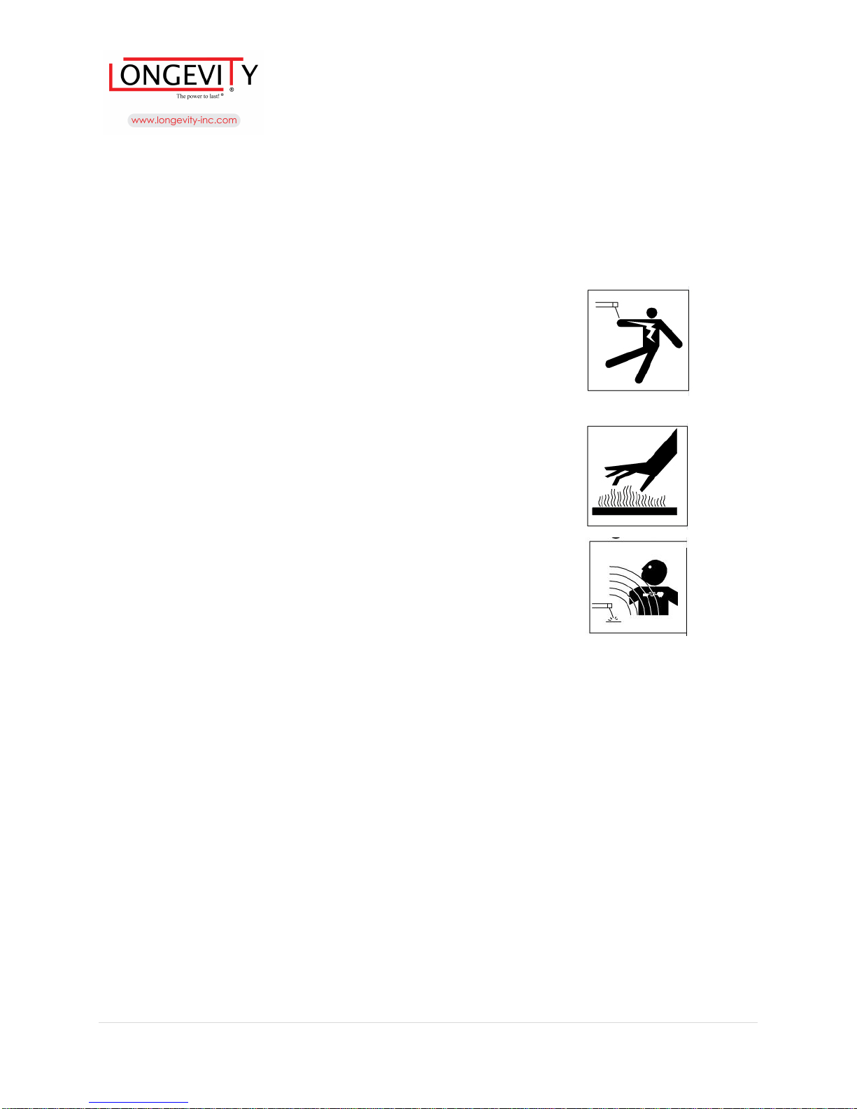
WARNING ARC WELDING can be hazardous
When using tool, basic safety precautions should always be followed to reduce the risk of
personal injury and damage to equipment Read all instructions before using this tool!
ELECTRIC SHOCK can KILL
Improper use of electric arc welders can cause electric
shock ,injury,and death! Take all precautions described in
this manual to reduce the possibility of electric shock.
FUMES AND GASES
Fumes and gases can be dangerous do net breathe fumes
that are produced by the arc welding operation .These fumes
are dangerous. Keep the head and face out of the welding fumes
Shielding gases used for arc welding can displace air and cause
injury or death. Always use enough ventilation, especially in
confined areas, to insure breathing air is safe.
WELDING SPARKS
Welding sparks can cause fire or explosion. DO not operate
any electric arc welder in areas where flammable or explosive
vapors may be present. Take precautions to be sure that flying
sparks and heat do not cause flames in hidden areas, cracks, etc.
Always keep a fire extinguisher accessible while performing arc
welding operations. Before starting or servicing any electric arc
welder, read and understand all instructions. Failure to follow safety
precautions or instructions can cause equipment damage and/or serious personal injury
or death. All installation, maintenance, repair and operation of this equipment
should be performed by qualified persons only in accordance with
national, state, and local codes
8 | P a g e
Page 9
SpoolGun 140 compatible with the MigWeld 140
ARC RAYS can burn.
Use a shield with the proper filter and cover plates to protect your eyes from sparks and the rays of
the arc when welding or observing open arc welding. Head shield and filter lens should conform to ANSI Z87
standards.
Use suitable clothing made from durable flame-resistant material to protect your skin and that of your helpers
from the arc rays. Protect other nearby personnel with suitable non-flammable screening and/or warn them not
to watch the arc nor expose themselves to the arc rays or to hot spatter or metal.
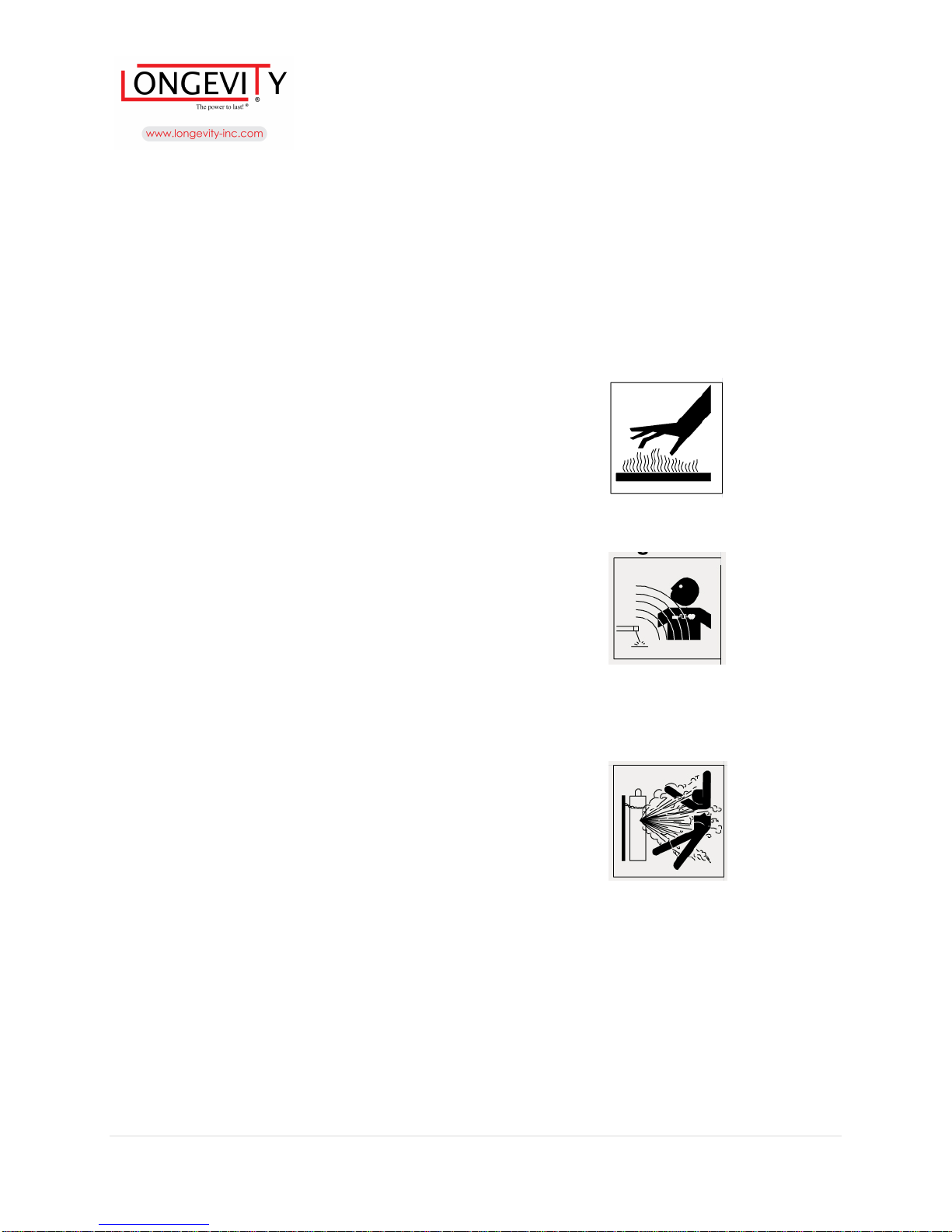
Heat metal can burn
Electric arc welding operations cause sparks and heat metal to
temperatures that can cause severe burns[ Use protective gloves and
clothing when performing any metal working operation.
Make sure that all persons in the welding area are protected from heat,
sparks, and ultraviolet rays. Use additional face shields and flame resistant
barriers as needed.
Never touch work pieces until completely cold.
ELECTRIC AND MAGNETIC FIELDS
Electric and magnetic fields may be dangerous. The electromagnetic field
that is generated during arc welding may interfere with the operation of
various electrical and electronic devices such as cardiac pacemakers.
Persons using such devices should consult with their physician prior to
performing any electric arc welding operations.
Route the wire gun and work cables together and secure with tape when
possible. Never wrap arc welder cables around the body.
Always position the wire gun and work leads so that they are on the same side of the body.
Exposure to electromagnetic fields during welding may have other health effects which are not known.
CYLINDER may explode if damaged.
Use only compressed gas cylinders containing the correct shielding gas
for the process used and properly operating regulators designed for the gas
and pressure used. All hoses, fittings, etc. should be suitable for the
application and maintained in good condition.
Always keep cylinders in an upright position securely chained to
an undercarriage or fixed support.
Cylinders should be located: Away from areas where they may be
struck or subjected to physical damage.
A safe distance from arc welding or cutting operations and any other source of heat, sparks, or flame.
Never allow the electrode, electrode holder or any other electrically "hot" parts to touch a cylinder.
Keep your head and face away from the cylinder valve outlet when opening the cylinder valve. Valve
protection caps should always be in place and hand tight except when the cylinder is in use or connected for
use.
Carefully read the operation manual prior to using, installing and maintaining the electric
welding machine for the purpose of preventing damages such as fire, electric shock and etc. from
occurring. Please keep the manual for the reference in the future
9 | P a g e
Page 10

SpoolGun 140 compatible with the MigWeld 140
Model SpoolGun 140
Welding Process Aluminum GMAW(MIG)
Wire Sizes(Diameters) Solid wire 0.030 or 0.035
inches
Spool Size 1 lb. weight ,4 inch diameter
spool
Rated Welding Current 130amps @30% duty cycle
Rated Input Voltage 12VDC
Wire Feed Rate 1.0-13m/min
NOTE: DUTY CYCLE is a welding equipment specification, which defines the number of
minutes, within a given time interval, during which a given welding machine can safely produce
a particular welding current, It is usually expressed as a ratio of the uninterrupted no-load
duration to the total time (usually 10 minutes)
10 | P a g e
Page 11

SpoolGun 140 compatible with the MigWeld 140
ITEM
DESCRIPTION
PART NO.
QTY
1 Nozzle
SB8-03-11 1 2
Contact tip
SB8-03-01 1 3
Diffuser
SB8-03-02 1 4
Neck Pipe
SB8-03-03 1
5 Shielding
Pipe SB8-03-07 1 6
Body Nut
SB8-01-06 1
7 Tight
Nut SB8-03-05 1 8
Hexagon
Connector
SB8-03-04 1 9
Liner Assembly
SB8-03-06 1 10
Driver Assembly
SB8-02-00 1 11
Copper Tag
SB8-03-08 1 12
Trigger
Assembly
SB8-04-00 1 13
Diffuser Pedestal
SB8-05-19 1 14
P6
Connector
SB8-05-18 4 15
Master Key Way
SB8-05-15 1 16
O Ring
18001250
2
17 Cable Assembly
SB8-05-00 1 18
Screw ST3.5*16
3
19 Roll SB8-02-13 1 20
Screw M4*5
1 21
Right Body
SB8-01-01 1 22
Left Body
SB8-01-02 1 23
Upper Spring
SB8-02-14 1 24
Lower Spring
SB8-02-15 1 25
Bearing
61800
-
2RS 1 26 Conical Spring
SB8-01-04 1 27
Cover Nut
SB8-01-05 1 28
Cover Assembly
SB8-01-03 1
29 Warning Sticker
SB8-01-07 1
11 | P a g e
Page 12
SpoolGun 140 compatible with the MigWeld 140
12 | P a g e
Page 13
SpoolGun 140 compatible with the MigWeld 140
Methods
Welding
ns
Shielding
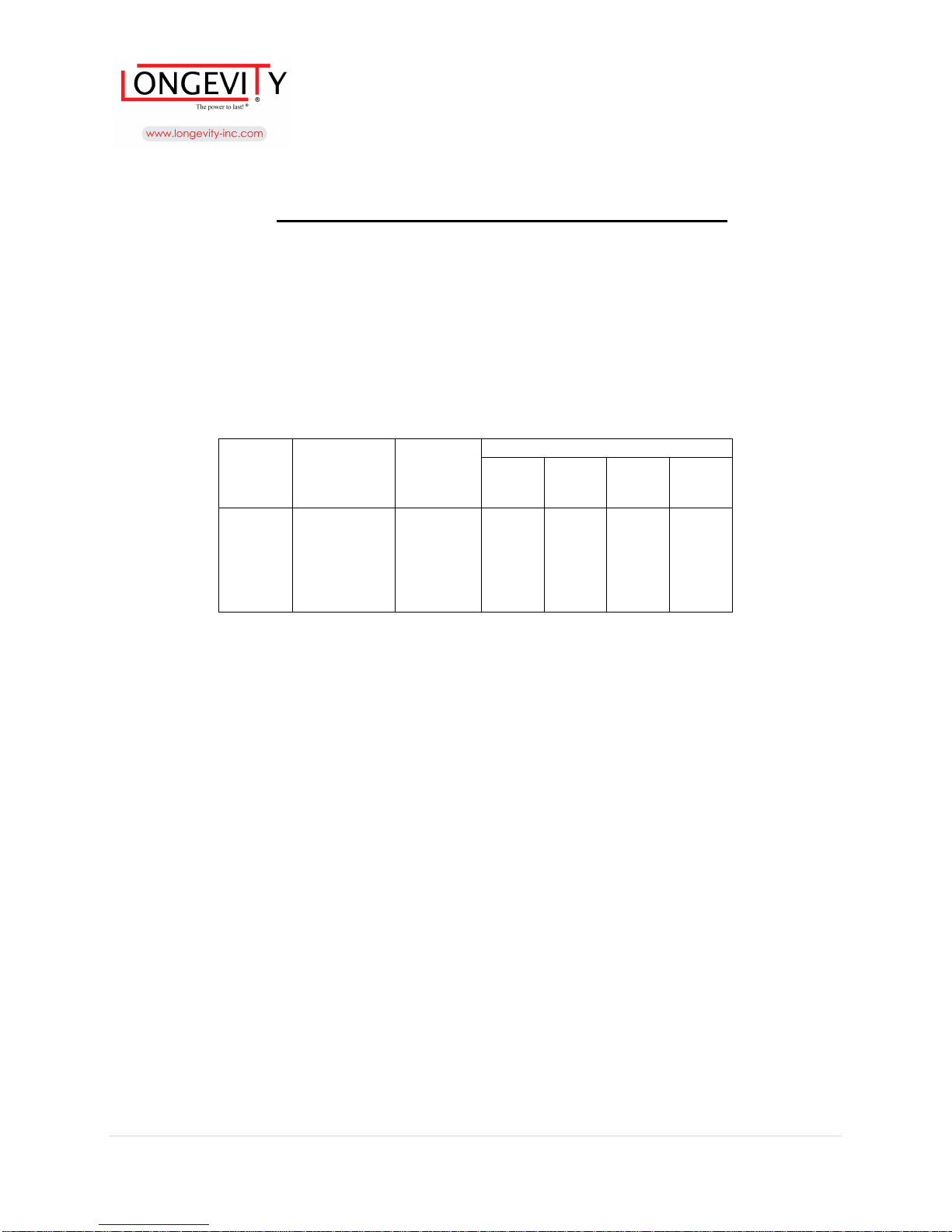
Voltage/Wire Feed Rate Regulation
0.8mm
1.6mm
2.5mm
3mm
MIG
Aluminum
09mm
100%
C-5 E-8 H-lO J-10
Voltage Tap Settings to Table D-1 (For MIG140).
1. Check the wire and then choose the polarity and decide if the gas should be used.
2. Connect earth clamp to the work piece and be sure the connection is in good
condition and in correct polarity.
3. Protecting with helmet press the trigger to weld. Keep the contact tip and
the work piece in a distance of 5-10mm.
4. To stop welding by just releasing the trigger.
5. Close the valve of the gas bottle (if the gas is used) when the welding work finished,
then press the trigger to discharge the compressed air inside the hose.
Reference parameters for Aluminum welding (Table D-l)
of
Welding
DC+
Wire
Specificatio
Welding
Wire
With
diameter at
GAS
Argon
Table D-1
13 | P a g e
Page 14
SpoolGun 140 compatible with the MigWeld 140
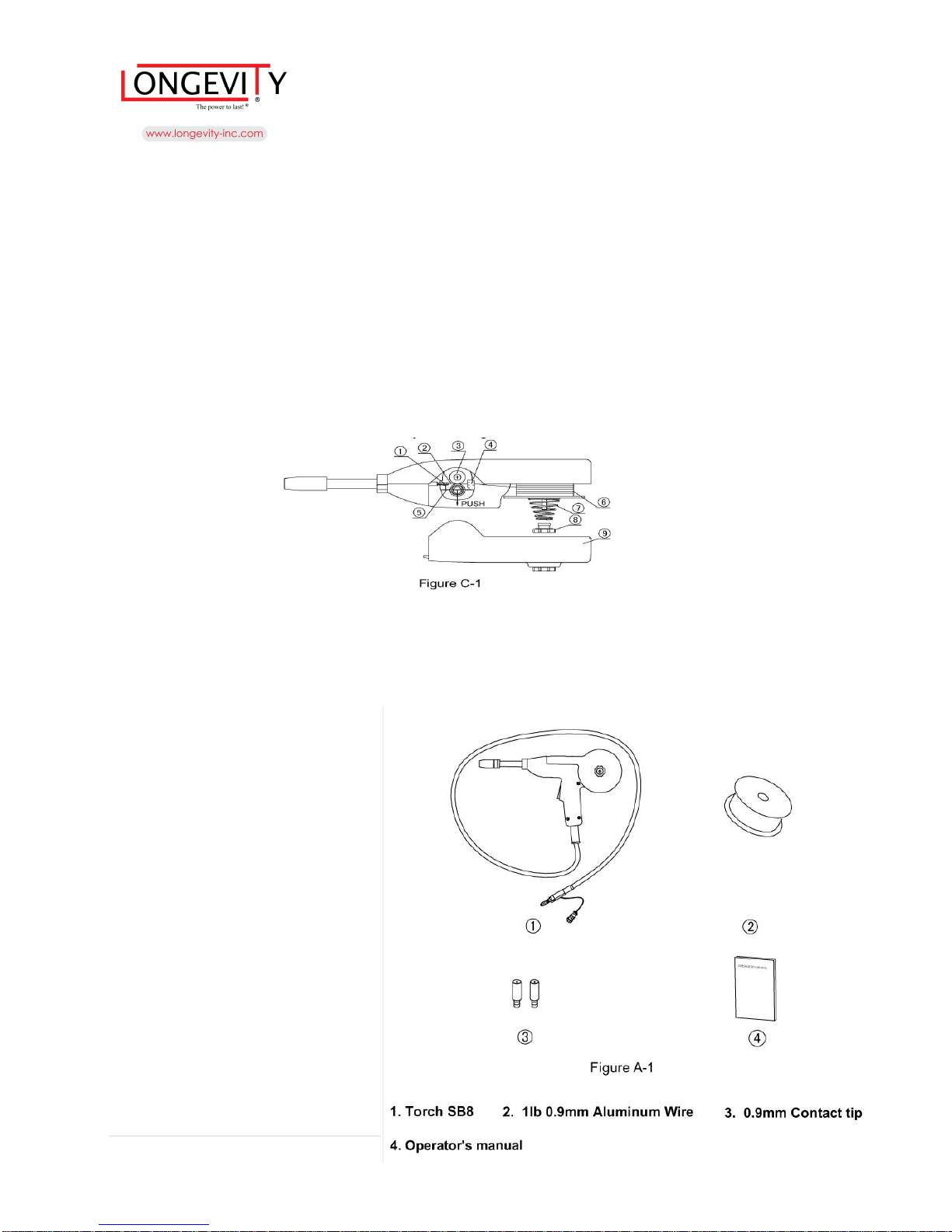
Loading Aluminum Wire (see FigureC-1)
1. Remove left cover (9), nut (8) ,conical spring(7) in sequence. Load4" (100mm) wire (6) on the spindle,
(note: the direction Of the wire running is counterclockwise). Then install back all removed parts followed
by conical spring, nut, left cover.
2. Extend approximately 12 inches of wire (2) from spool. Straighten it out by back-bending it. Use care to
prevent the wire from unwinding.
3. Cut Off bent end of wire, leaving 100mm long straight section
4. Gently pull open the idle roll assembly to expose the drive roll grove. Guide straightened wire through inlet
wire guide (4) and toward drive roll groove (3).
While holding open the idle roll (5), slide end of wire through drive roll's groove and toward gun tube liner
(1).
5. Release the idle roll assembly and the straightened wire.
Welding Procedure
1 .Connect input power to the machine.
2, Screw off the nozzle and contact tip,
3~ Press the trigger, then the driver feeds the wire into the gun, Release the trigger when wire come out from
the mouth of the gun,
4. Screw on the contact tip and nozzle.
5. Cut off the aluminum wire so that it extends about 1/4 inches (6-10mm) from the contact tip.
When welding
1. Select suitable wire and gas
according to the type and thickness of
the work piece refer to related Welding
Manual.
2. According to the wire and thickness
of the work piece set wire speed and
Unpacking
When unpacking, check to make sure
the following parts are include
(See Figure A-l)
14 | P a g e
Page 15
SpoolGun 140 compatible with the MigWeld 140
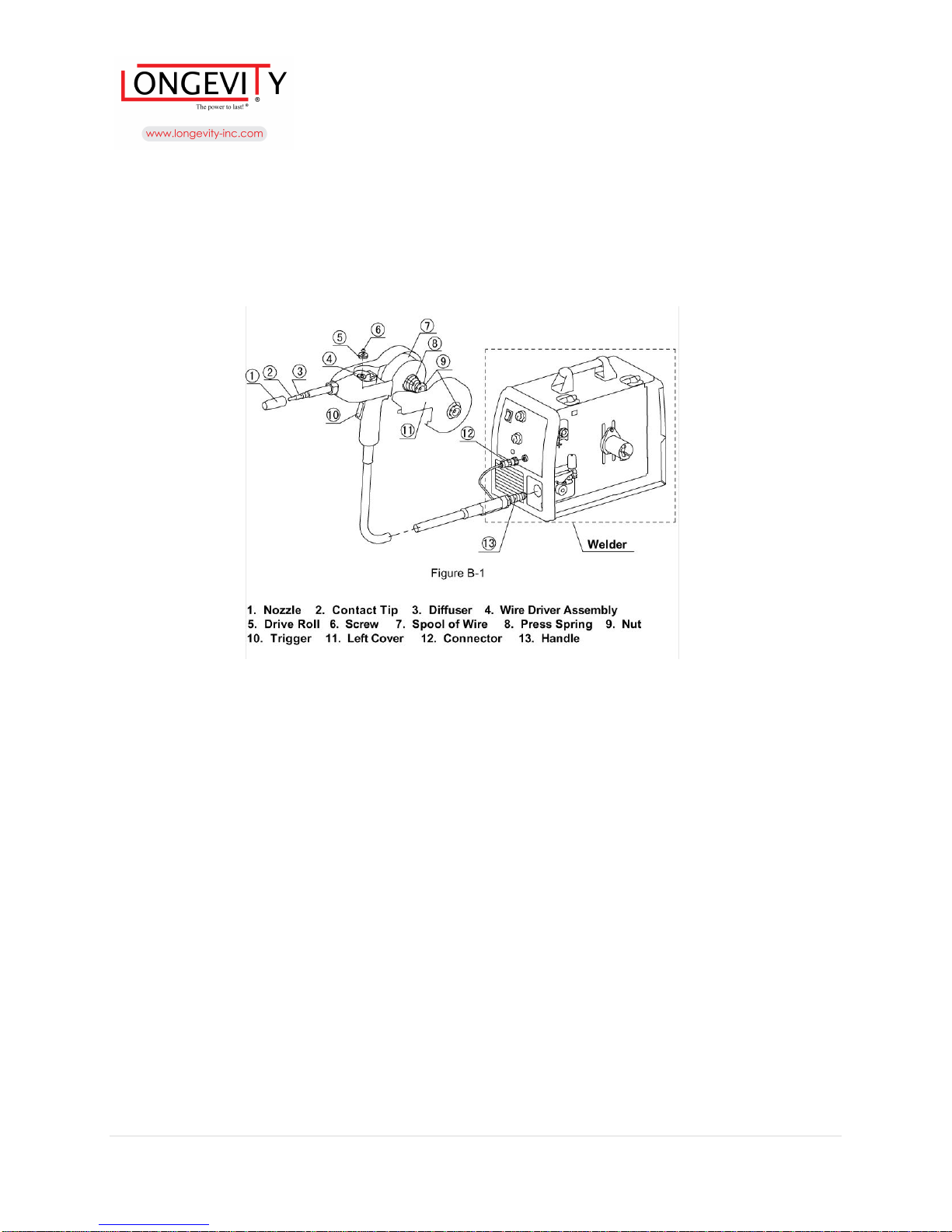
Components and Controls (See Figure B-1 )
Installation Spool Gun (See Figure B-1)
Connecting the gun to the welding machine
1, Disconnect input power to the machine
2, Fully insert gun cable connection (welding power and gas supply)
3, Plug P6 Connector Control Leads into the P6 Connector Key Way on the
machine and turning until it be located in the position
15 | P a g e
Page 16
SpoolGun 140 compatible with the MigWeld 140
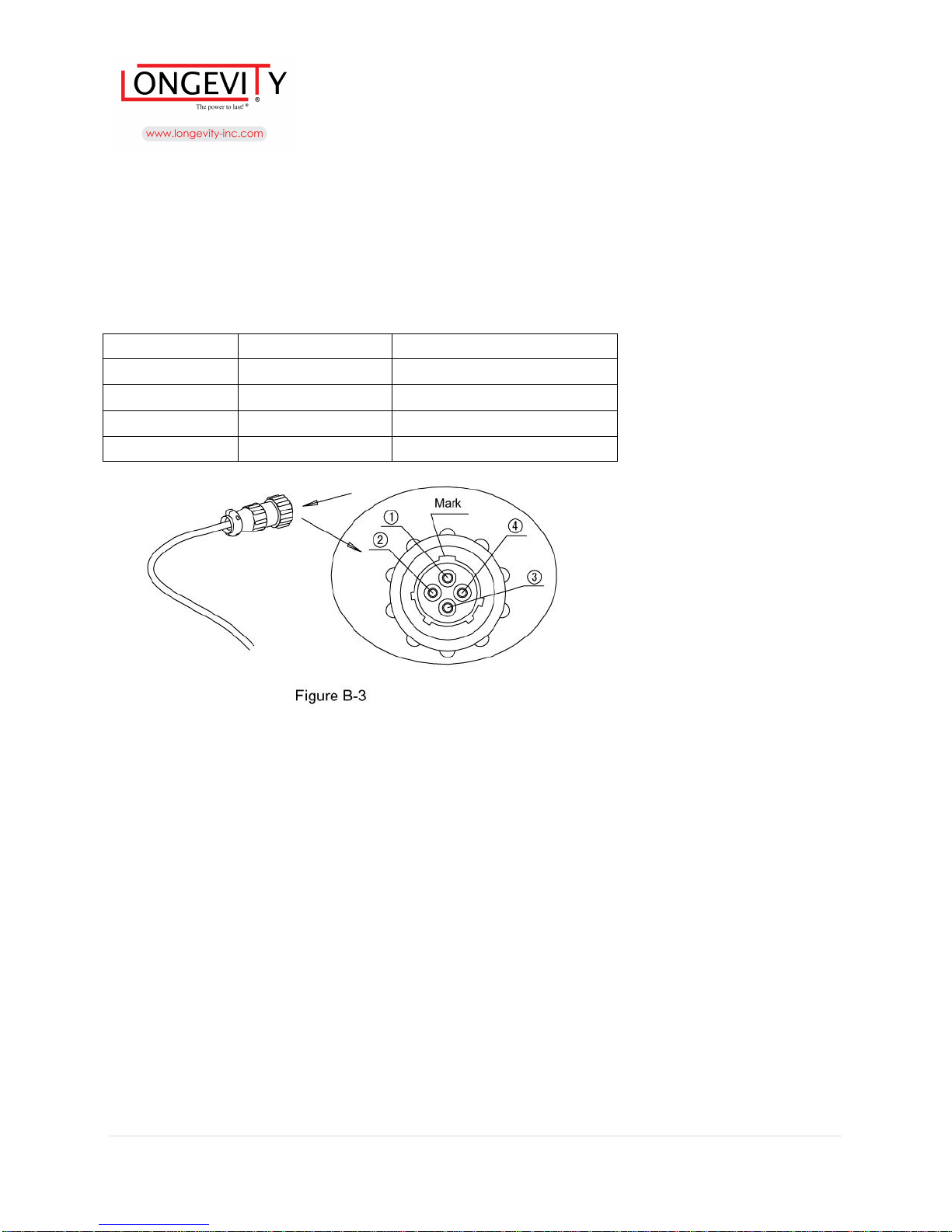
P6 Connector Pin-out (See Table B-2 and Figure B-3)
Pin No. Function Gun Cable Lead Color
1 Trigger Yellow
2 Trigger Green
3 + Motor Red
4 - Motor White
Drive Roll Replacement (see Figure B-1 )
Qne piece of 0.gram roll for SB8 installed in factory.
Replace the drive roll if necessary. The procedure of replacement is as follows.
1. Unscrew the screws (6)
2. Take out the roll (5)
3, Put the roll in position and screw to secure it (6)
16 | P a g e
Page 17

SpoolGun 140 compatible with the MigWeld 140
LONGEVITY® Global, Inc. thanks you for your purchase and the opportunity to be able to serve you. If,
after reviewing this manual, you have any problems in setting up or operating your machine, contact us
at [email protected].
LONGEVITY® Global, Inc.
Toll-Free 1-877-LONG-INC / 1-877-566-4462
Website: www.longevity-inc.com
Sales: [email protected]
Customer Service: [email protected]
Dealers: [email protected]
For the coolest LONGEVITY sponsored race teams plus a complete racing forum that covers everything
from Drag Racing to RC Car Racing, please check out www.longevity-racing.com!
Enjoy your new welding machine from LONGEVITY! Thanks again!
17 | P a g e
 Loading...