

Page 1

ForceCut 42i 110v/220v PFC 40amp Plasma Cutter
Operating Manual
For
ForceCut 42i
110v/220v PFC 40AMP Plasma Cutter
1
Page 2

ForceCut 42i 110v/220v PFC 40amp Plasma Cutter
Table of Contents:
PG. 3: Thank you From LONGEVITY
PG. 4-6: Warranty/Shipping Damage/Order Information
PG. 7-9: Warning and Safety Information
PG. 10: Specifications and Ratings
PG. 11: Installation
PG. 12: Front Panel
PG. 13: Basic Operation
PG. 14: Cutting Methods
PG. 15: PT-60 Torch Breakdown
PG. 16-18: Troubleshooting
PG. 19: Electrical Schematics Drawing
PG. 20: Routine Maintance
PG. 21: Enjoy your new welding machine from LONGEVITY!
2
Page 3

ForceCut 42i 110v/220v PFC 40amp Plasma Cutter
THANK YOU!
We, at LONGEVITY, want to thank you for purchasing our product. You are almost ready to
experience Longevity Welding first hand. Longevity definitely appreciates your business and
understand that this equipment may be overwhelming to setup and operate so we have prepared a
manual that will assist you in understand your new plasma cutter/welder. If you have any questions
during or after reading this manual, please feel to contact us! Please take a moment to register your
product on our website at www.longevity-inc.com or www.lweld.com
Once again, thank you for choosing Longevity as your main welding supplier!
3
Page 4

ForceCut 42i 110v/220v PFC 40amp Plasma Cutter
Longevity Global, Inc.
23591 Foley St
Hayward, CA 94545
Toll-Free Customer Support: 1-877-LONG-INC / 1-877-566-4462
Website: www.longevity-inc.com
Sales: [email protected]
Customer Service: [email protected]
Dealers: [email protected]
Complaints: [email protected]
Please join our welding forums to share welding tips and tricks, to receive useful information from
customers who also use our products, and to be a part of the Longevity™ welding community at
www.freeweldingforum.com
Check out LONGEVITY Racing at www.longevity-racing.com
4
Page 5

ForceCut 42i 110v/220v PFC 40amp Plasma Cutter
W
arranty
LONGEVITY Plasma Cutters, Welders, and Multi-Purpose Welders are covered for specific Parts and
Labor warranty at our facility. For detailed information regarding your specific LONGEVITY welder or
cutter, please view our Terms and Policies page on our website at the following website link:
http://www.longevity-inc.com/terms/
.
Shipping Damage
Your machine is insured against damage during shipping. Keep all packing materials and containers in
case machine must be returned. We will initiate a claim with the shipping company to cover damage
or loss. If there is shipping damage upon opening your package, our customer service team will work
with you to get the matter resolved.
5
Page 6

ForceCut 42i 110v/220v PFC 40amp Plasma Cutter
In Warranty Service
Customers, who own machines that are in warranty and require service, should contact our Warranty
Department by email at [email protected] to obtain a return authorization code. In addition to
the warranty we offer, we would like for you to register your product on our website at
www.longevity-inc.com/resources. Remember, warranty starts from the date of purchase. For your
convenience, write your order information below so you can track your order in case you need
warranty work.
Order No.: _________________________________
Date of Purchase: _____________________________
Warranty Period: ______________________________
Out-of-Warranty Service
Customers, who own machines that are out of warranty and require service, should contact us for an
estimate. Longevity offers an exchange program on out of warranty units. We also help non
LONGEVITY customers with repairs, replacement, and service.
If your unit is not manufactured by Longevity and you cannot receive service from your manufacturer
or seller, Longevity will lend out hand. Our warranty policy is also available for all plasma cutters and
welders. For more information, please email us at [email protected]
6
Page 7
ForceCut 42i 110v/220v PFC 40amp Plasma Cutter
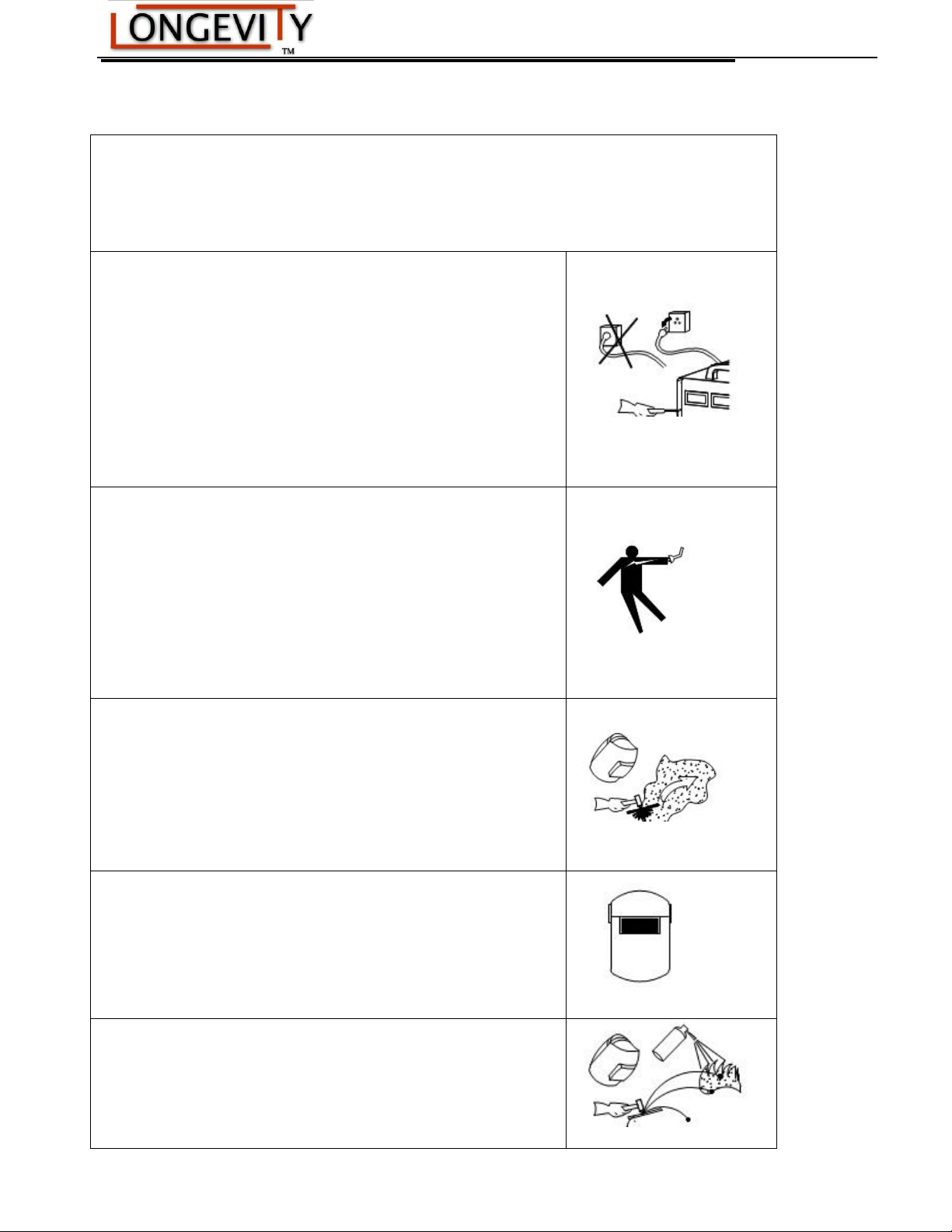
Welding and plasma cutting may be dangerous to the operator and to bystanders, if the
equipment is not operated properly. Welding or cutting must be performed in accordance with
all relevant safety regulations. Carefully read and understand this instruction manual before
installing and operating this equipment.
Changing function modes during welding may damage
equipment.
Before welding, disconnect the electrode-holder cable from the
equipment.
A circuit breaker is required to prevent electrical overload of the
equipment.
Only high quality welding tools should be used.
Electric Shock can be fatal.
Ensure that ground cable is connected in accordance with
applicable safety codes.
Never touch electrodes, wires, or circuit components with bare
hands. Wear dry welding gloves when welding.
The operator must be insulated from the work piece.
Smoke and gas can be harmful to health.
Ensure that the working area is well ventilated.
Avoid breathing smoke and gas generated during the welding
process. Cutting and welding can cause cancer because of the
smoke that comes from the welds and cuts.
Arc-light emission can be harmful to eyes and skin.
Always wear a welding helmet, anti-radiation glass, and work
clothes while welding.
Ensure that people in or near the working area are protected.
Welding splash is a fire hazard.
Keep flammable material away from the work place.
Keep a fire extinguisher nearby, and have all personnel trained in
Warnings and Safety
7
Page 8

ForceCut 42i 110v/220v PFC 40amp Plasma Cutter
its use.
Surface noise generated while welding or cutting can be harmful
to hearing.
In the event of a machine fault.
Refer to this instruction manual.
If the fault cannot be determined, contact your local dealer or
supplier for assistance.
8
Page 9

ForceCut 42i 110v/220v PFC 40amp Plasma Cutter
Safety Tips
Consider the following tips to ensure safe operation of your welding/cutting equipment:
Ensure that this welding equipment is installed in an area free of corrosive chemical gases,
flammable gases or materials, and explosive chemicals.
The area should contain little dust, and have a humidity of no more than 80%.
Operate the welding equipment in an area sheltered from direct sunlight and precipitation. Work
area temperature should be maintained at - to
If, because of an overload, the machine suddenly stops, and it is necessary to restart it, leave the
internal fan operating to lower the inside temperature.
Always wear protective clothing and a welding mask to protect your skin.
Wear safety goggles designed to darken the arc generated by your machine.
Wear suitable noise protection to protect your hearing.
Ensure that machine is grounded through the power cord or on the machine case.
Never operate the machine in bare feet or on a wet floor.
Never switch the machine off while it’s in use. Doing so will damage the internal circuitry.
Ensure that your circuit breaker is rated to handle the current requirements of your machine.
Use a UL approved receptacles and plugs with your machine. Never hard wire the machine to
main power.
Work in a well-ventilated area to avoid smoke. Keep your head out of the smoke. Ensure that air is
flowing away from you to avoid inhaling smoke.
Ensure proper ventilation through the machine’s louvers. Maintain a distance of at
inches between this cutting equipment and any other objects in the work area.
Use a screen or curtain designed to keep passer byes from viewing the arc.
The arc spray and metal spray from machine use may cause nearby fires. Use caution.
If, after reviewing this manual, you have any problems in setting up or operating your machine,
contact us at [email protected].
least 12
9
Page 10

ForceCut 42i 110v/220v PFC 40amp Plasma Cutter
Rated input
Single-phase,220V/110V,50/60Hz
Rated input current(A)
23.4(220V)
33.7(110V)
Rated input power(KW)
4.63(220V)
3.44(110V)
Adjustment range of current(A)
20~40(220V)
20~30(110V)
Duty cycle(40℃,10 minutes)
40%(220V)
35%(110V)
Max no-load voltage(V)
480 volts
Weight
36 lbs
Dimensions (Length*Width*Height)
18”L x 8”W x 15”H
Operation Manual
Carefully read the operation manual prior to using, installing and maintaining the electric welding
machine for the purpose of preventing damages such as fire, electric shock and etc from occurring.
Please keep the manual for the reference in the future.
Specifications and Parameters
NOTE: DUTY CYCLE is welding equipment specification, which defines the number of minutes, within a
given time interval, during which a given welding machine can safely produce a particular welding
current. It is usually expressed as a ratio of the uninterrupted no-load duration to the total time
(usually 10 minutes)
10
Page 11

ForceCut 42i 110v/220v PFC 40amp Plasma Cutter
Installation
Unpacking
1. Inspect each item for possible shipping damage. If damage is evident, contact your distributor and / or shipping
company before proceeding with the installation.
Input Power Connections
Note: Check your power source for correct voltage before plugging in or connecting the unit
Gas Connections
A. Connecting Gas Supply to Unit
Connect the gas line to the inlet port of the gas filter on the rear panel.
B. Check Air Quality
To test the quality of air, put the RUN / SET switch in the SET (down) position, check if there are Any oil or moisture
in the air.
11
Page 12
ForceCut 42i 110v/220v PFC 40amp Plasma Cutter
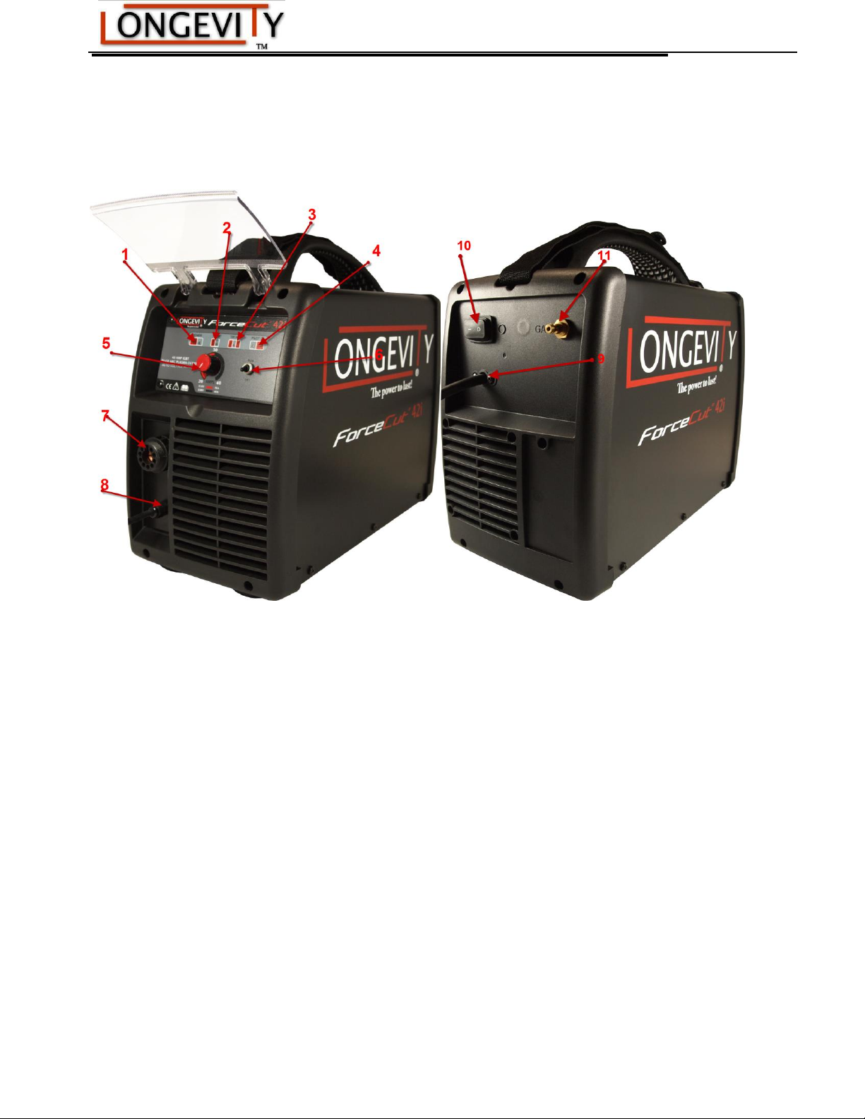
Layout Of The Front And Rear Panel
1. Power Light: The light will illuminate when the unit is powered on
2. Temperature /Over-Heat Light: When the duty cycle is reach, the TEMP will turn on. Once it is safe to operate
the machine, the light will turn off. If duty cycle is reached, allow machine to run with the fan on to accelerate
cooling.
3. Tip/Air Light
When adequate air pressure is reached, the Tip/Air light should turn on
4. Pilot/Voltage Light: The Pilot/Voltage light is illuminated when the machine is ready to use.
5. Amperage Control Knob: Allows the user to precisely set the desired amperage output. The machine is
limited to 30A when connected to 110v power supply
6. RUN/SET: When cutting the, turn the switch to “RUN”; when doing a gas test, turn to the “SET”.
7. Cutting gun connector: Connector for the PT-60 plasma torch
8. Ground Clamp: Connect to the workpiece or a secure ground
9. Power Cable: connect to the desired power supply(110v/220v)
10. Power Switch turns on or off the machine
11. Air connector (Note: air pressure had setted inside. That is 4bar/60psi)
12
Page 13

ForceCut 42i 110v/220v PFC 40amp Plasma Cutter
Basic Operation
1. Ensure that all cables are connected to the machine.
2. Ensure that the machine’s OFF/ON switch is set to OFF, and plug the machine into the electrical
outlet.
3. Connect the air compressor supply line to the air input side on the unit.
4. Turn the ON/OFF switch to ON. The cooling fans should operate and the ON indicator LED or power
switch (if applicable) should illuminate.
5. Clean the contact point on the work piece to ensure a good electrical connection. Ensure that no rust
of paint is present that could create an open circuit.
6. Connect the ground clamp to the work piece to be cut.
7. Connect the torch to the unit properly.
8. With the pilot arc knob connected, you should get a full continuous arc when the trigger on the torch
is pressed.
9. Depress the button on your torch to start the arc and begin cutting.
10. You can test the air to insure that is it properly flowing by selecting Gas (Air) Test. Air will pass
through the torch.
11. If necessary remove slag from the under part of the cut using a grinder or chisel.
13
Page 14
ForceCut 42i 110v/220v PFC 40amp Plasma Cutter
LP-
40D
Cutting Guideline Table
Cutting Methods
Different material thicknesses require different cutting techniques.
Thin material: Start perpendicular to the work piece. It is unnecessary to angle or start on the
edge, as the arc will pass through quickly.
Medium material: Angle the torch tip to avoid damaging the tip. Once the arc passes through the
material, you may begin cutting normally.
Thick material: Drill a pilot hole through which to start your arc, or start on the edge of the work
piece.
Never cut material on a flat surface. Raise the work piece above the surface to avoid blow back which
may burn you or cause fires.
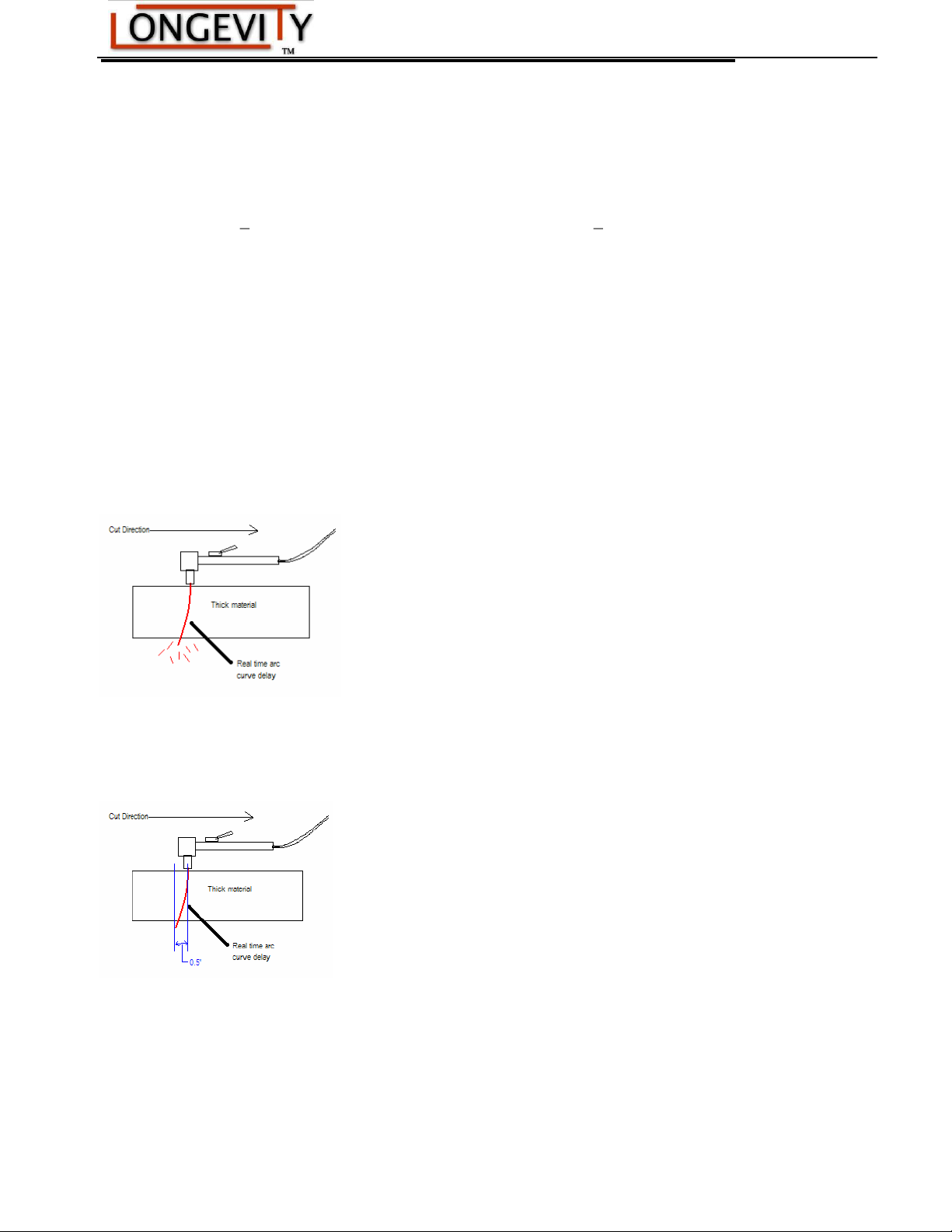
Real Time Arc-Curve Delay
When cutting thick materials you must maintain a steady even motion in the direction of the cut. Moving
the torch too quickly causes an arc-curve delay. An arc-curve delay can leave the work piece with uncut
sections, requiring you to re-cut those sections, which could distort or damage the work piece.
To avoid arc-curve delay, allow the arc to pass completely through the work piece before moving too far
ahead. The arc-curve should lag not more than the thickness of the material being cut. In other words, if
the work piece is one-half inch thick, the arc curve should lag not more than one-half inch behind the
torch, as shown below.
14
Page 15
ForceCut 42i 110v/220v PFC 40amp Plasma Cutter
15
Page 16

ForceCut 42i 110v/220v PFC 40amp Plasma Cutter
Troubleshooting
WARNING
There are extremely dangerous voltage and power levels present inside this unit. Do not attempt to diagnose or
repair unless you have had training in power electronics measurement and troubleshooting techniques.
A. The cutting torch fails to ignite the arc, when press on the torch switch, the TIP/GUN/GAS light on.
1. Gas pressure too high, gas test then adjust gas pressure to 4bar/60psi.
B. The cutting torch fails to ignite the arc, when the torch switch is pressed; the TIP/GUN/GAS lamp turns on.
1. The shield cup is improperly installed. Turn off the power source, install the shield cup properly, and then turn on
the power source.
C. The cutting torch fails to ignite the arc, when press on the torch switch, the TIP/GUN/GAS lamp on and air
feed intermittently.
1.The electrode or nozzle improper installation, turn off the power source, install the electrode or nozzle, and screw
shield cup down properly, then turn on the power source.
D .The cutting torch fail to ignite the arc, when press on the torch switch, the TIP/GUN/GAS lamp on and air
feed intermittently.
1. Short-circuit for burned-out and other abnormal situation, turn off the power source, and change the electrode and
nozzle.
E. Power lamp and temperature lamp on.
1. Air flow blocked, check for blocked air flow around the unit and correct condition.
2. Fan blocked, check and correct condition.
3. Unit is overheated, let unit cool down for at least 5 minutes. Make sure the unit has not been operated beyond
Duty Cycle limit, refer to technology parameters in Section 2.
4. Faulty components in unit, return for repair or have qualified technician repair per Service Manual.
F. Torch fails to ignite the arc when torch switch is activated
1. System is in SET mode,change to RUN mode.
2. Faulty torch parts, inspect torch parts and replace if necessary.
3. Gas pressure too high or too low, adjust to proper pressure.
4. Faulty components in unit, return for repair or have qualified technician repair per Service Manual.
16
Page 17

ForceCut 42i 110v/220v PFC 40amp Plasma Cutter
G. No cutting output; Torch activated, power source on; Gas flows; Fan operates
1. Torch not properly connected to power supply, check that torch leads are properly connected to
power supply.
2. Work cable not connected to work piece, or connection is poor, make sure that work cable has a
proper connection to a clean, dry area of the workpiece.
3. Faulty components in unit, return for repair or have qualified technician repair per Service Manual.
4. Faulty Torch, return for repair or have qualified technician repair.
H. Low cutting output
1. Incorrect setting of CURRENT (A) control, check and adjust to proper setting.
2. Faulty components in unit, return for repair or have qualified technician repair.
I. Difficult Starting
1. Worn torch parts (consumables), shut off input power. Remove and inspect torch shield cup, tip and
electrode. Replace electrode or tip if worn; replace shield cup if excessive spatter adheres to it.
J. Arc shuts off during operation; arc will not restart when torch switch is activated.
1. Power Supply is overheated (OC/OT lamp on), let unit cool down for at least 5 minutes. Make sure
the unit has not been operated beyond Duty Cycle limit. Refer to Section 2 for duty cycle specifications.
2. Gas pressure too low (the TIP/GUN/GAS lamp on when press on torch switch is on), check source
for at least 4bar/60psi; adjust as needed. It is need to open the machine cover.
3 Torch consumables worn, check torch shield cup, tip, starter element, and electrode; replace as
needed.
4. Faulty components in unit:, return for repair or have qualified technician repair per Service Manual.
K. No gas flow; the power lamp on; Fan operates
1. Gas not connected or pressure too low, check gas connections. Adjust gas pressure to proper setting.
2. Faulty components in unit, return for repair or have qualified technician repair.
17
Page 18

ForceCut 42i 110v/220v PFC 40amp Plasma Cutter
L. Torch cuts but cuts are of low quality
1. Amperage control set too low, increase current setting.
2. Torch is being moved too fast across workpiece, reduce cutting speed.
3. Excessive oil or moisture in torch, hold torch 1/8 inch (3 mm) from clean surface while
purging and observe oil or moisture buildup (do not activate torch). If there are contaminants
in the gas, additional filtering may be needed.
18
Page 19
ForceCut 42i 110v/220v PFC 40amp Plasma Cutter
T1
T2
R2 5
R2 4
D10
R2 0
R1 6
ZD3
T13
D12
R2 2
R1 8
ZD5
T15
QD2
QD5
QD6
QD1
QD2
C1
R1 0
R1 1
B2
IN2GND
4
VCC
8
OUT
7
OUT
6
GND
5
NC3VCC
1
U4
IN2GND
4
VCC
8
OUT
7
OUT
6
GND
5
NC3VCC
1
U5
C2
C3
R3 2
R3 3
T4
T5
R2 9
R2 8
R3 6
R3 7
ZD3- 1
ZD5- 1
R5 1
R5 0
R5 2
T16 -1
T14 -1
R1 00
R1 01
C1 00
COU T1
COU T2
GDN
GDN
ZBY Q
R4 9
C2 0
C2 1
ZBY Q
ZBY Q
TR8
OC1 OC2
DC +
C1 8
C1 6
R4 7
D5
C
1
L
2
X
3
S
4
F
5
D
6
U7A
C0
C6
D6
TVS1
D7
D15
D9
D16
D17
C1 1
C1 5
C1 3 C1 4
C4 5
C4 6
D8
C7 C8 C9 C1 0
D18
C4 3
U9
R9 1
R9 0
ZD8 ZD 9
C4 1
R9 3
R9 2
R8 8
R8 9
C4 0
R8 5
R8 6
R8 7
+24 V1
+01
-24V
123
WV OUT
B3
D28
D27
C4 2 C2 5 C27 C28
R3 0
OC
D50
D51
D52
D53
R8 4
C5
C4
OC1
OC2
HF
12345
DY2
1234567
IN
R8 4-4
R8 4-1 R8 4-2
C1 01
D5- 1
R0 4
R0 1
1
2
ZYO UT
L1
L3
L5
L2
T10 -1
OR1
IN2GND
4
VCC
8
OUT
7
OUT
6
GND
5
NC3VCC
1
U6
OR2
C4 4C4 7
ZD4
R1 25
C1 26
R1 30
1
2
QD
C4 8
R1 32
C4 9
PFC 10 T(3X 3. 2)/1 4T(1 .8X 2. 6)
ZD6
R1 29
C1 9
C1 7
OUT +1
OUT +
0UT-
D19
R3 1
C5 2
OUT +1
U8
1
2
DY1
QD6
QD6
QD5
QD1
V13
PUV LO15SYN C
16
IPK
2
MULT
8
CAOUT
5
ISENSE
9
COSZ
18
ROSZ
17
SS
12
VREF
11
LFF
6
SGND
10
PGND
1
VP
3
GDR V
20
VFEED
14
VA-OUT
13
VCC
19
IAC
4
VRMS
7
49 81
C1 41
R1 55
R154
R1 53
QD6
C1 21
R178
C1 10
R1 77
R182
R1 81
R1 75
C1 22
QD6
R1 80R 176
R1
QD6
R1 83
C1 09
R1 72
C1 24
QD6
R1 56
R1 57
R2 3
R1 52
R1 51
R1 50
C1 42
C1 03
QD6
L4
V8 V8- 1
R1 79
R1 79 -1
V9
V9- 1
V12
C1 23
R1 74
V7
V7- 1
R1 73
R1 69
R1 68
R1 67
QD6
R1 58
R1 71
R1 70
C1 07
QD6
DC+
QD6
C1 08
C1 20
CX
R186
C0 0R0 0
C5 3
B4
C5 4
1
2
OC2
1
2
OC1
D21
D20
D13
D11
ZD7
R9 4
DC-
D+1
2
D+
1
2
D-
1
3
4
5
2
U1
123
4
IFIN
123
4
IFOUT
12345
6
XFIF /IN/OU T
R1 27
R1 28
R1 33 R 13 4
C5 7
R0 2
R5 3R4 1 R 40R 42R 44 R4 3R4 5R4 6R19 0R3 8-1R48 R1 89R3 8
R3 9-1R 64R 39R 55 R5 4R6 3R5 7 R 56R 18 7R1 88R5 8R 60R62 R 59R 61
QD6
C1 06
C1 05 -3
+UB 7
15
2
+0V
0V
Dnd
Vin
F1 515 S-1 W
F1 515 S-3
15 V
R200
R203
R201
R204 R2085
R202
R206
15 V
+UB
CU3
CU4
GDN
CY1
AC3
AC4
R2 00 -2
R1 84 R1 85
ZD2 T6
C1 43
-24V
D14
J1
R2 00 -1
1
2
RX
AC2
AC1
TR1
CU1 CU2
C1 44
1
2
AC2
1
2
AC1
1
2
AC3
1
2
AC4
1
+
3
GND
2
OUT
4
IN
5
IN
5
OUT
6
OUT
6
HL
1
2
3
4
XHIF
R3 4
C5 1
+UB
1
2
DYJC
C5 0
7
1 5
2
+0V
0V
Dnd
Vin
F1515S-1W
F1 515 S
7
1 5
2
+0V
0V
Dnd
Vin
F1515S-1W
F1 515 S-2
+12 v
+12 v
12 v
12 v
C1 2 C22
C2 3
C2 4
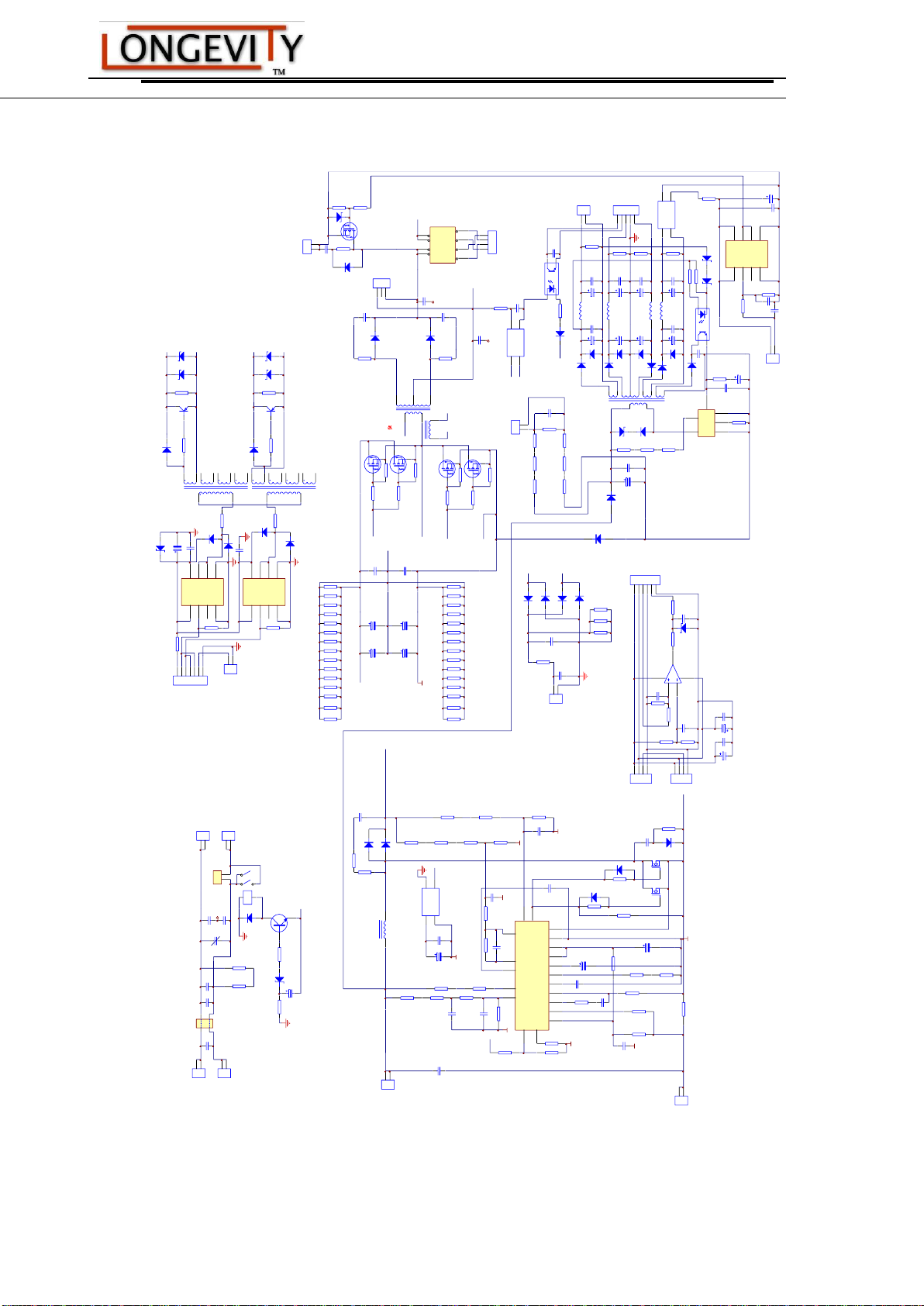
Electrical Schematics Drawing
19
Page 20

ForceCut 42i 110v/220v PFC 40amp Plasma Cutter
Routine Maintenance
The life of your machine and the quality of the work performed using your machine, will be
enhanced by practicing periodic routine maintenance.
• At regular intervals, clear dust that may accumulate in the machine using clean and dry
compressed air. If the working condition has heavy smoke and pollution, the welding machine
should be cleaned once a month.
• Keep the machine exterior clean with mild soap and water.
• Do not walk on or store items on the cables or cords.
• Do not jar, drop, or stack items on top of the machine.
• Always connect the machine to a well-grounded electrical outlet.
• Always check the torch consumables before and after use and ensure that they are clear of
obstructions, and that no parts are damaged.
• Replace any worn or damaged consumables before using machine.
• For periods of prolonged non-use, remove cables and store them in their original boxes in a
cool dry place.
20
Page 21

ForceCut 42i 110v/220v PFC 40amp Plasma Cutter
LONGEVITY® Global, Inc. thanks you for your purchase and the opportunity to be able to serve
you. If, after reviewing this manual, you have any problems in setting up or operating your
machine, contact us at [email protected].
LONGEVITY® Global, Inc.
Toll-Free 1-877-LONG-INC / 1-877-566-4462
Website: www.longevity-inc.com
Sales: [email protected]
Customer Service: [email protected]
Dealers: [email protected]
Please join our welding forums to share welding tips and tricks, to receive useful information
from customers who also use our products, and to be a part of the LONGEVITY® welding
community at www.freeweldingforum.com
For the coolest LONGEVITY sponsored race teams plus a complete racing forum that covers
everything from Drag Racing to RC Car Racing, please check out www.longevity-racing.com!
Enjoy your new welding machine from LONGEVITY! Thanks again!
21
 Loading...