

Page 1
Operating Manual
for
Page 2

MIGWELD 250 MP
Table of Con tent
Pg. 1
Thank you From LONGEVITY
Pg. 2
Warranty/Shipping Damage/Order Information
Pg. 3
Safety Information
Pg. 4-5
Specifications and Ratings
Pg. 6
What’s Inclu ded?
Pg. 7
Main Unit Kno b/But ton/Func tion D iagra m
Pg. 8
General View of Control Panel
Pg. 9
Parameter and Settings
Pg. 15
Welding Parameters
Pg.17
STICK Process
Pg. 18
MIG Torch Description
Pg. 20
Changing Wire Spool
Pg. 25
Changing Wire Feeders
Pg. 26
Spool Brake Settings
Pg. 28
MIG/MAG/Co2 Display Settings
Pg. 29
Pulse MIG Displa y Setti ngs
Pg. 33
MIG Welding Tips and Tricks
Pg. 37
STICK Welding Tips and Tricks
Pg.44
Routine Maintenance
Pg. 51
Contact Info
Pg. 52
Table of Contents
1
Page 3

MIGWELD 250 MP
THANK YOU!
We, at LONGEVITY, want to thank you for purchasing our product. You are almost ready to
experience Longevity Welding first hand. Longevity definitely appreciates your business and
understand that this equipment may be overwhelming to setup and operate so we have prepared a
manual that will assist you in understand your new welder. If you have any questions during or
after reading this manual, please feel to contact us! Please take a moment to register your
product on our website at www.longevity-inc.com or www.lweld.com
Once again, thank you for choosing Longevity as your main welding supplier!
Longevity Global, Inc
d
Hayward, CA 94545
Toll-Free Customer Support: 1-877-LONG-INC / 1-877-566-4462
Website: www.longevity-inc.com
Sales: [email protected]
Customer Service: [email protected]
Dealers: [email protected]
Complaints: [email protected]
Please join our welding forums to share welding tips and tricks, to receive useful information
from customers who also use our products, and to be a part of the Longevity™ welding
community at www.freeweldingforum.com
2
Page 4

MIGWELD 250 MP
Warranty
LONGEVITY Plasma Cutters, Welders, and Multi-Purpose Welders are covered for specific Parts
and Labor warranty at our facility. For detailed information regarding your specific LONGEVITY
welder or cutter, please view our Terms and Policies page on our website at the following website
link: http://www.longevity-inc.com/terms/
Shipping Damage
Your machine is insured against damage during shipping. Keep all packing materials and containers
in case machine must be returned. We will initiate a claim with the shipping company to cover
damage or loss. If there is shipping damage upon opening your package, our customer service team
will work with you to get the matter resolved.
In Warranty Service
Customers, who own machines that are in warranty and require service, should contact our Warranty
Department by email at [email protected] to obtain a return authorization code. In addition to
the warranty we offer, we would like for you to register your product on our website at
www.longevity-inc.com/resources. Remember, warranty starts from the date of purchase. For your
convenience, write your order information below so you can track your order in case you need
warranty work.
Order No.: _________________________________
Date of Purchase: _____________________________
Warranty Period: ______________________________
Out-of-Warranty Service
Customers, who own machines that are out of warranty and require service, should contact us for an
estimate. Longevity offers an exchange program on out of warranty units. We also help non
LONGEVITY customers with repairs, replacement, and service.
If your unit is not manufactured by Longevity and you cannot receive service from your manufacturer or
seller, Longevity will lend a hand. Our warranty policy is also available for all plasma cutters and
welders. For more information, please email us at: [email protected]
3
Page 5

MIGWELD 250 MP
Welding and plasma cutting may be dangerous to the operator and to bystanders, if the
before installing and operating this equipment.
Changing function mo de s during welding may damage
Electric Shock can be fatal.
Warnings and Safety
equipment is not operated properly. Welding or cutting must be performed in accordance
with all relevant safety regulations. Carefully read and understand this instruction manual
equipment.
Before welding, disconnect the power cable from the
equipment.
A circuit breaker is required to prevent electrical
overload of the equipment.
Ensure that ground cable is connected in accordance with
applicable safety codes.
Never touch electrodes, wires, or circuit components with
bare hands. Wear dry welding gloves when welding.
The operator must be insulated from the work piece.
Smoke and gas can be harmful to health.
Ensure that the working area is well ventilated.
Avoid breathing smoke and gas generated during the
welding process. C ut ti ng and weld ing can cause cancer
because of the smoke that comes from the welds and cuts.
Arc-light emission can be harmful to eyes and skin.
Always wear a welding helmet, anti-radiation glass, and
work clothes while welding.
Ensure that people in or near the working area are
protected.
Welding splash is a fire hazard.
Keep flammable material away from the work place.
Keep a fire extinguish er nearby, and have all personnel
trained in it’s use.
Surface noise generated while welding or cutting can be
harmful to hearing.
In the event of a machine fault.
Refer to this instruction manual.
If the fault cannot be determined, contact your local
dealer or supplier for assistance.
4
Page 6

MIGWELD 250 MP
Safety Tips
Consider the following tips to ensure safe operation of your welding/cutting equipment:
• Ensure that this welding equipment is installed in an area free of corrosive chemical gases,
flammable gases or materials, and explosive chemicals.
• The area should contain little dust, and have a humidity of no more than 80%.
• Operate the welding equipment in an area sheltered from direct sunlight and precipitation.
Work area temperature should be maintained at -10°C to +40°C;
• If, because of an overload, the machine suddenly stops, and it is necessary to restart it, leave
the internal fan operating to lower the inside temperature.
• Always wear protective clothing and a welding mask to protect your skin.
• Wear safety goggles designed to darken the arc generated by your machine.
• Wear suitable noise protection to protect your hearing.
• Ensure that machine is grounded through the power cord or on the machine case.
• Never operate the machine in bare feet or on a wet floor.
• Never switch the machine off while it’s in use. Doing so will damage the internal circuitry.
• Ensure that your circuit breaker is rated to handle the current requirements of your machine.
• Use a UL approved receptacles and plugs with your machine. Never hard wire the machine to
main power.
• Work in a well ventilated area to avoid smoke. Keep your head out of the smoke. Ensure that
air is flowing away from you to avoid inhaling smoke.
•
• Use a screen or curtain designed to keep passers by from viewing the arc.
• The arc spray and metal spray from machine use may cause nearby fires. Use caution.
•
If, after reviewing this manual, you have any problems in setting up or operating your
Ensure proper ventilation through the machine’s louvers. Maint ain a distance o f at
12 inches between this equipment and any other objects in the work area.
machine, contact us at [email protected].
least
5
Page 7

MIGWELD 250 MP
Techinical Specifications and Ratings
Rated input Single-phase, 220/240V/50/60Hz
Input Power Capacity 9KVA
No-load Voltage 58V
Rated Output MIG: 250A/26.5V
Current/Voltage MMA: 200A/28V
Rated Duty Cycle 60%
Pulse Frequency 0.1-9.9Hz
Pulse Width (Balance) 10-90%
Arc Inductance Degree 1-10
Pre-Gas/Glow-Gas Time 0.1-3.0S
Wire Spool Capacity 300mm (15kg)
Wire Diameters 0.8-1.2mm
Dimensions 31.5L x 13W 25.5H
Weight 76.9 Lbs
6
Page 8
MIGWELD 250 MP
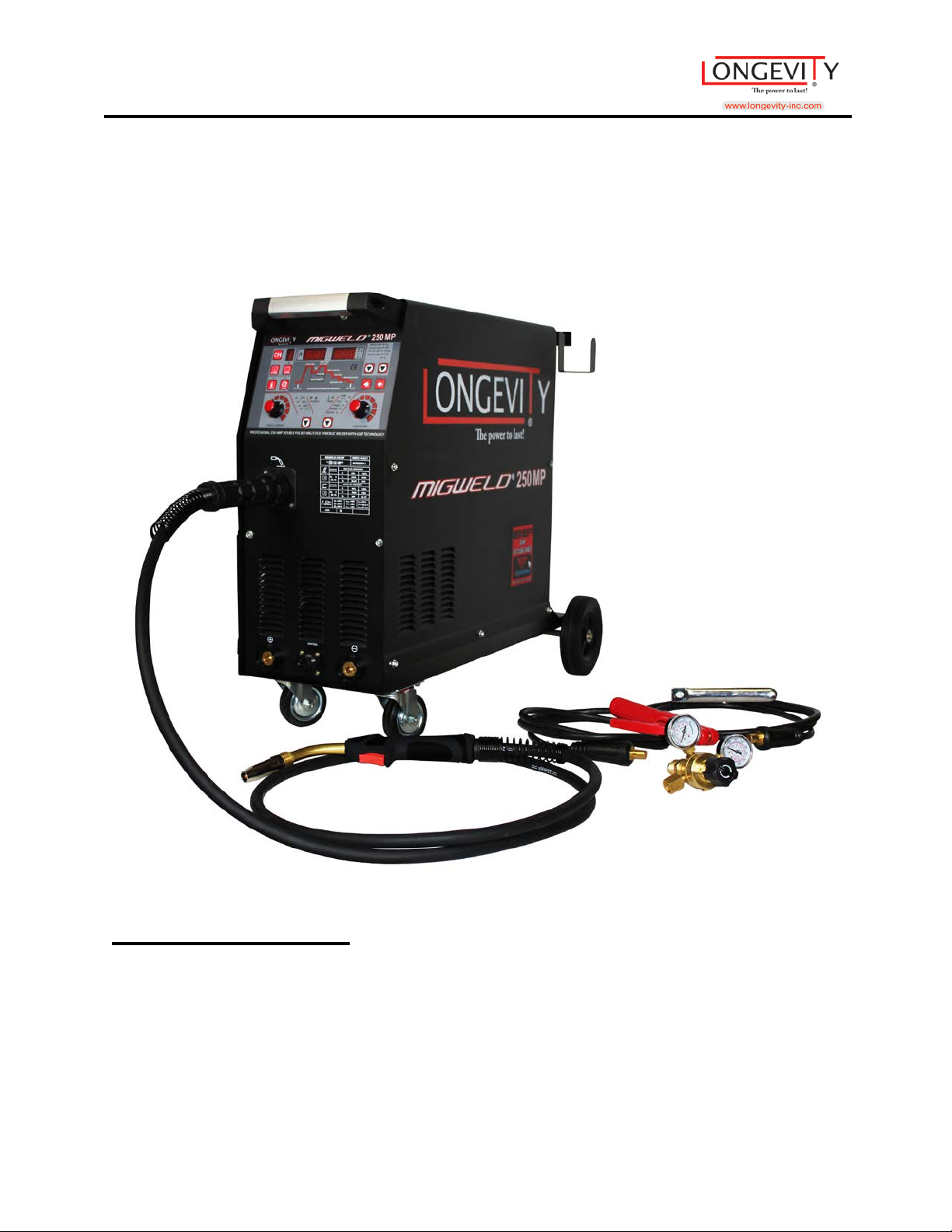
What’s Included?
1 6 FT Ground Clamp
1 5 FT Stinger
1 9 FT 24K MIG Torch
1 24K MIG Nozzle~ 1 1-0.040 Contact Tip~ 1 Contact holder~ 1diffuser
1 C02 Regulator
1 Wheel Base
7
Page 9
MIGWELD 250 MP
2
3
1
5
7 86 94
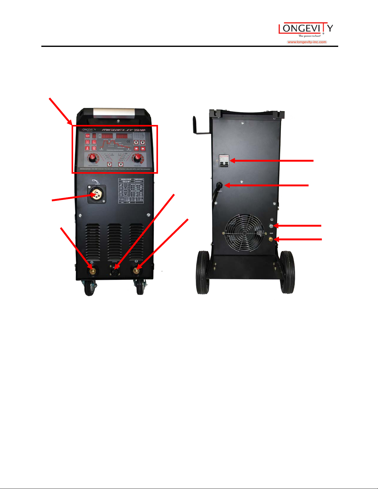
Main Unit
Pictured: MIGWELD 250 MP
Main Unit Knob/Bu tton/Function :
1. Control Panel
2. Welding Torch Connection
3. Positive Connector
4. Remote Control lead ~ Push Pull Torch Control Lead~ Spool Gun Control Lead
5. Negative Connector
6. Power Switch
7. Power Cable
8. Ground/Earth Connector
9. Shielding Gas Connector
8
Page 10
MIGWELD 250 MP
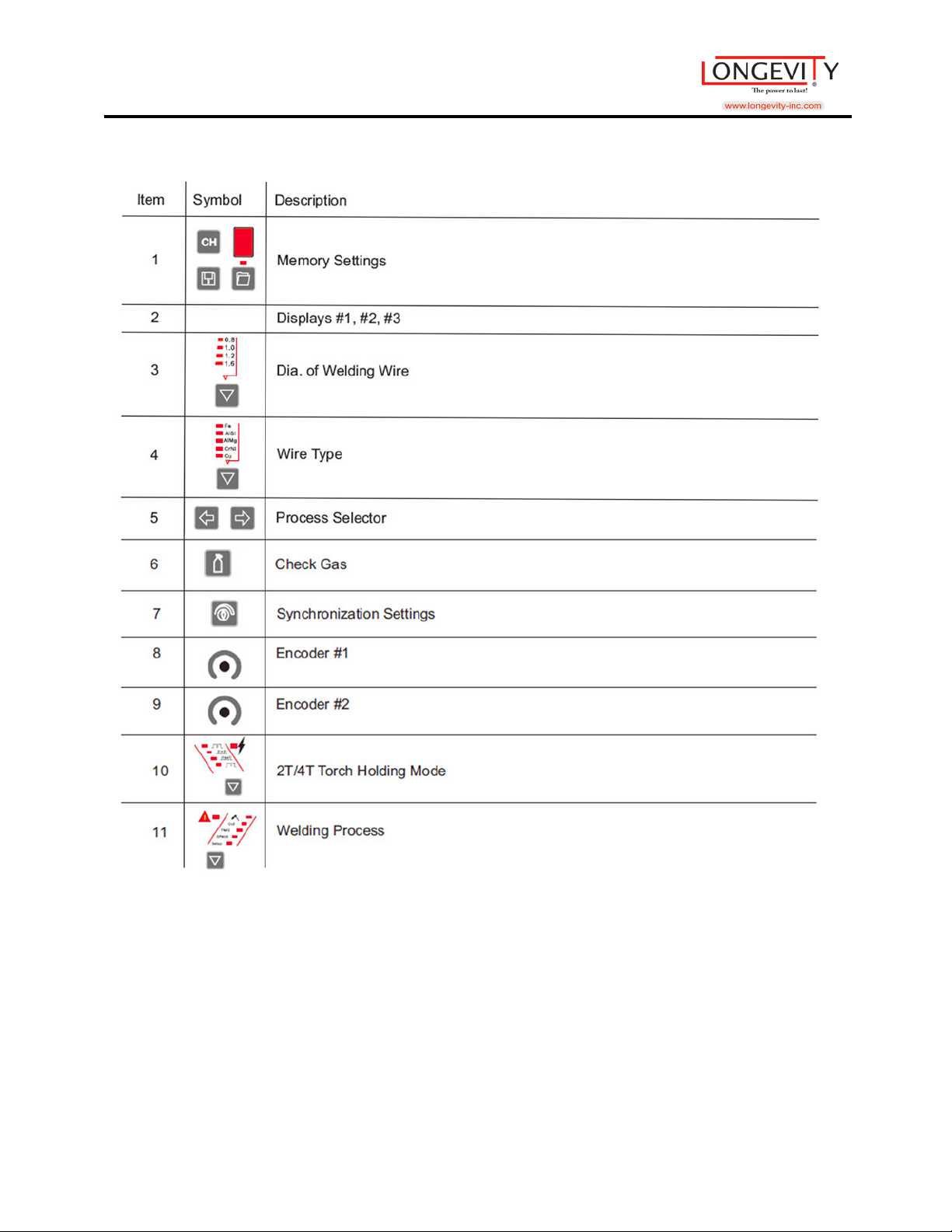
1
2 3 6
4 8 7
9 5 11
10
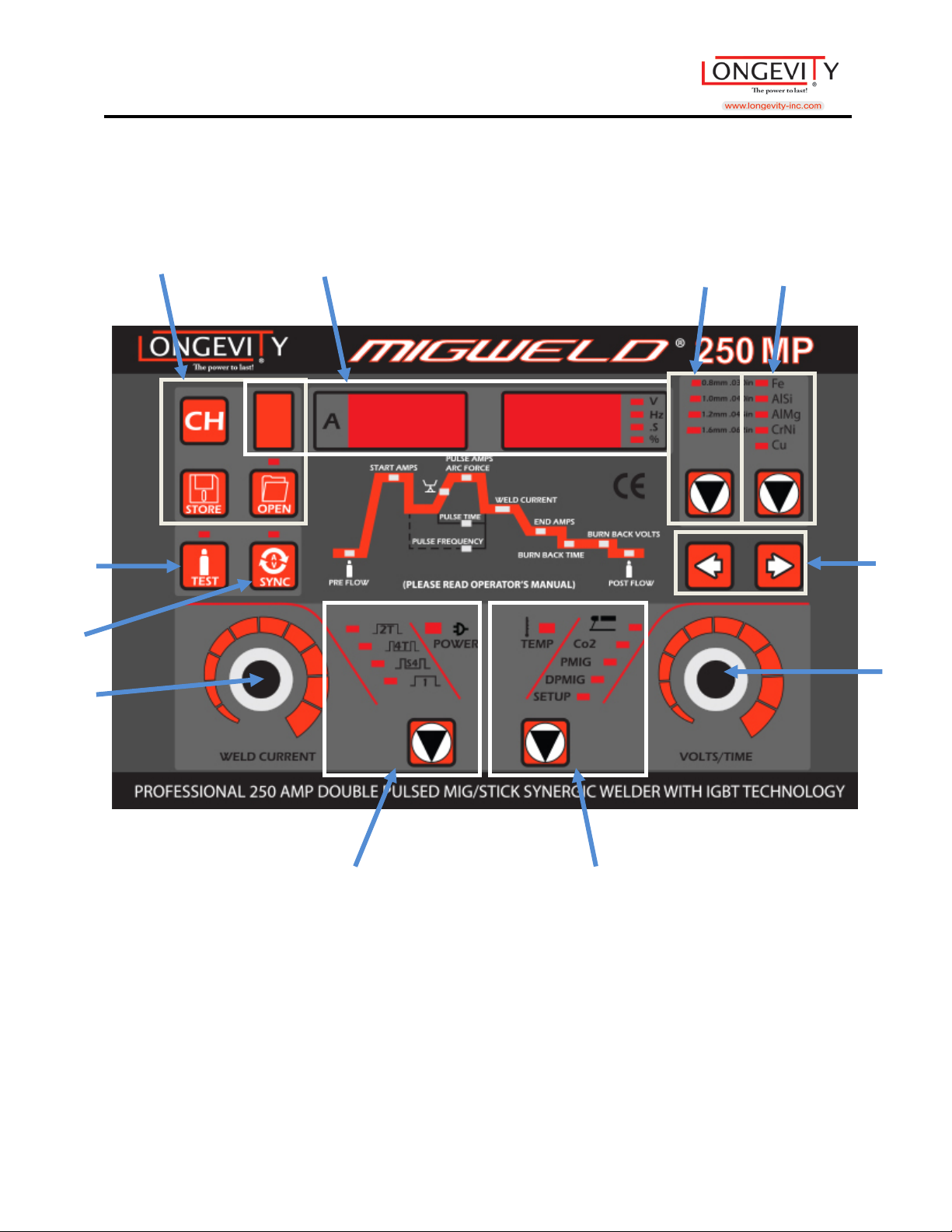
General View of Control Panel
9
Page 11
MIGWELD 250 MP
10
Page 12
MIGWELD 250 MP
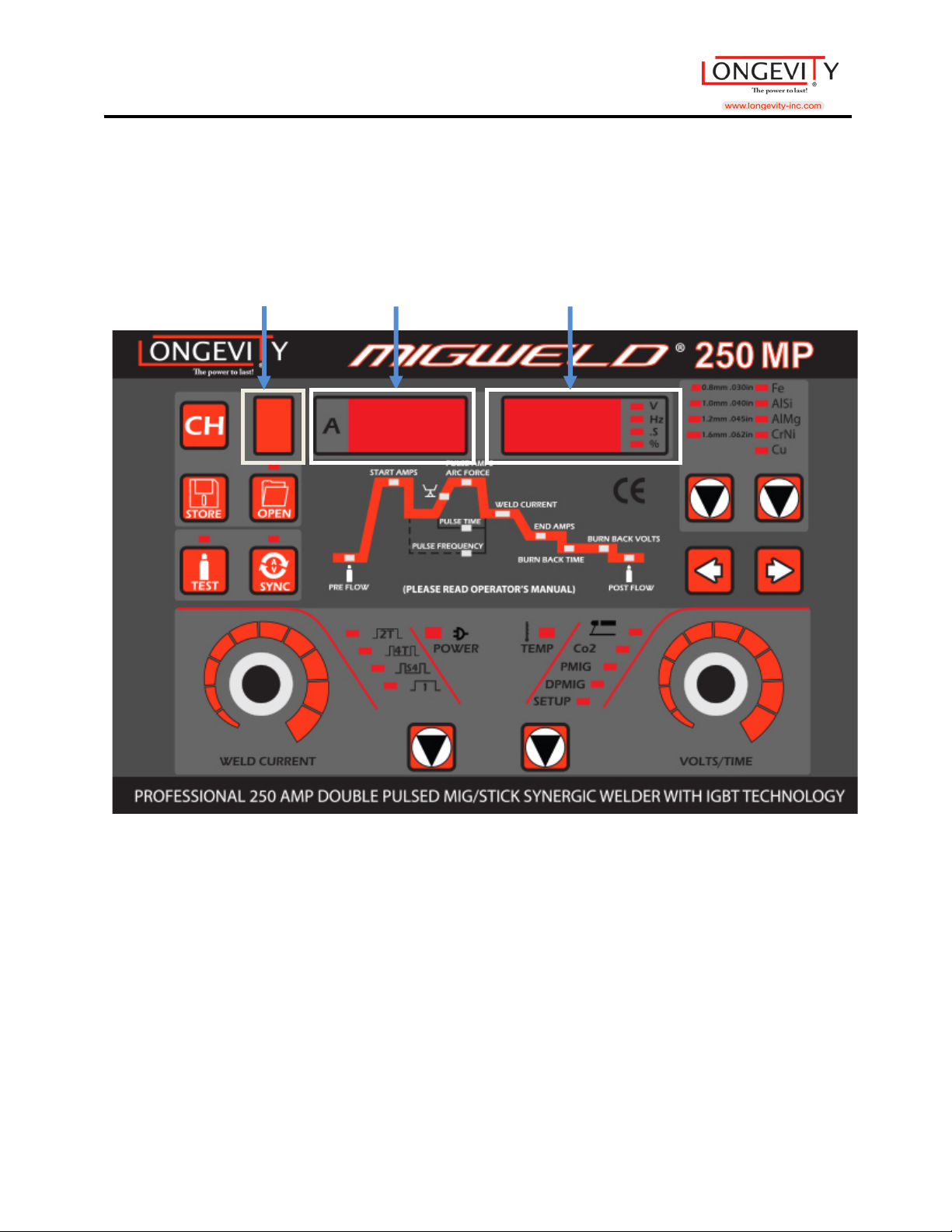
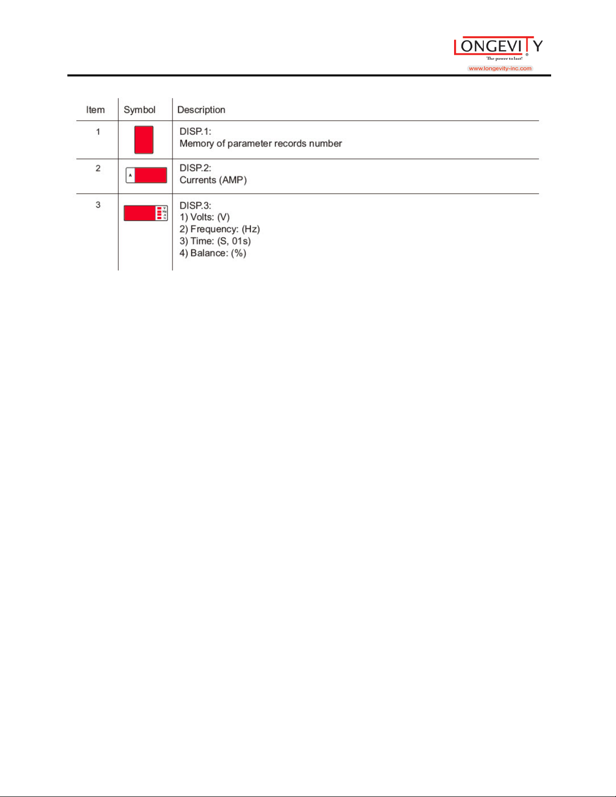
1 2 3
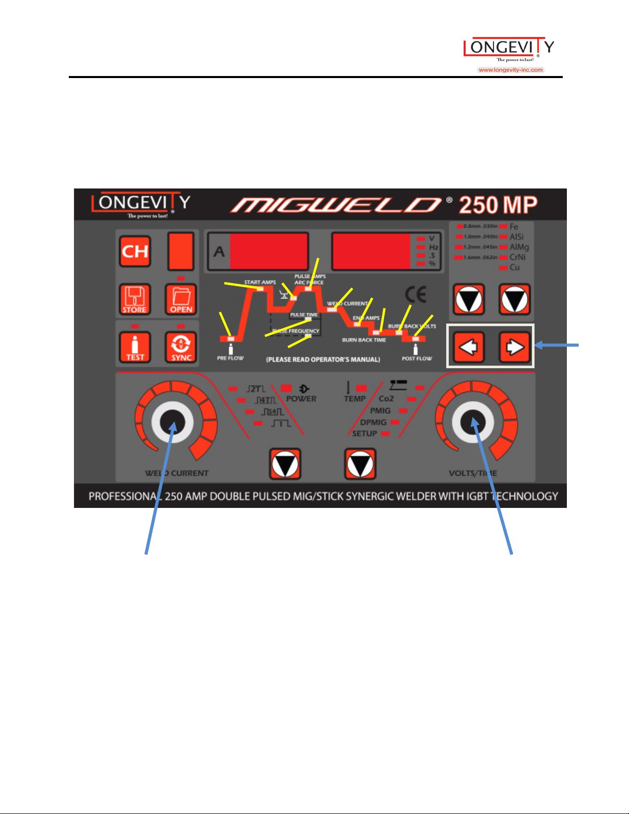
Parameter and Settings Displays
11
Page 13
MIGWELD 250 MP
12
Page 14
MIGWELD 250 MP
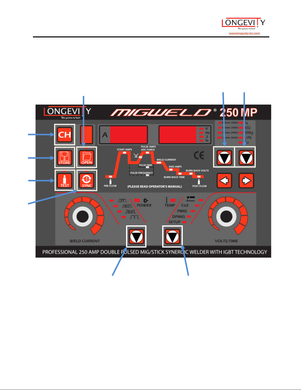
4 2 1 3 8
9
7
6
5
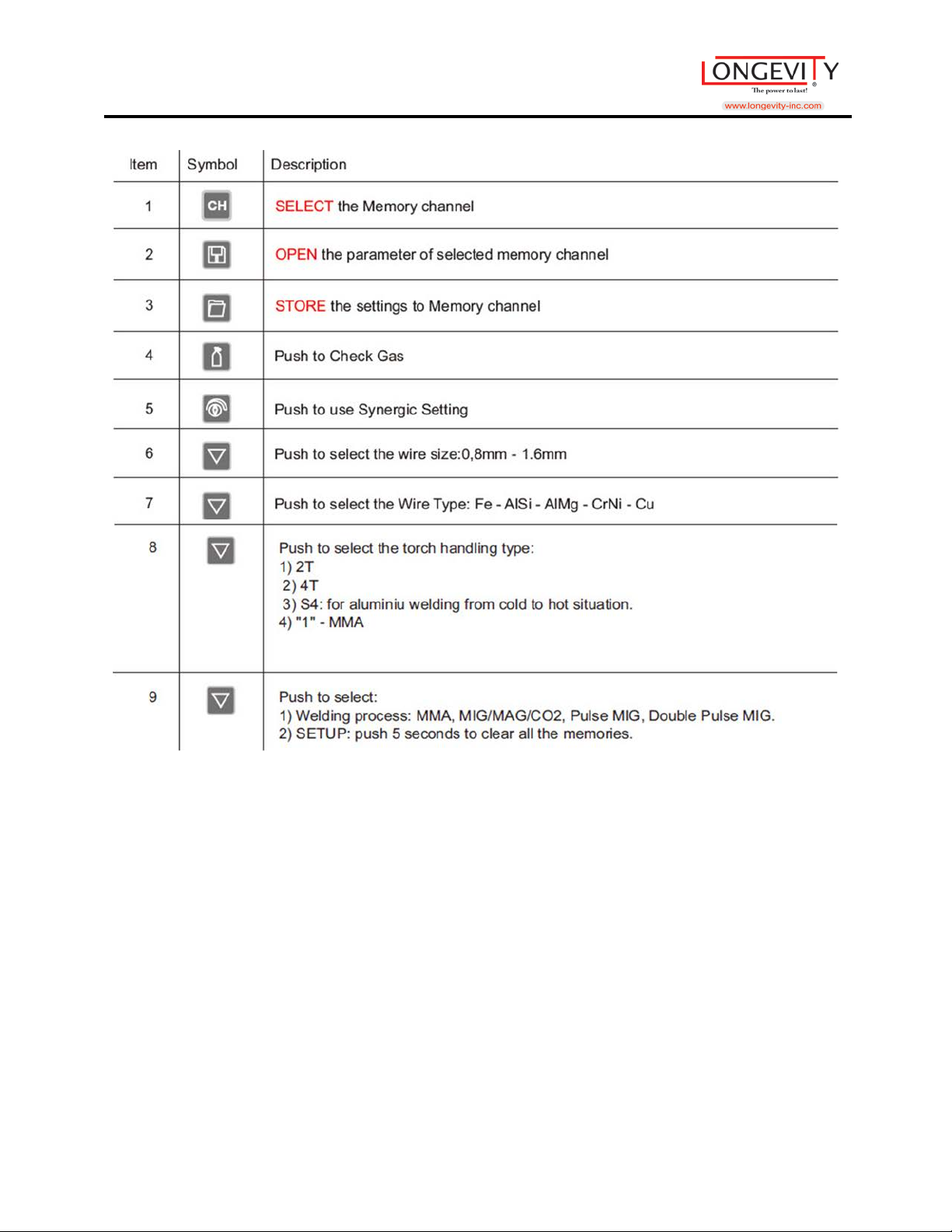
Welding Process and Status Controls
13
Page 15
MIGWELD 250 MP
14
Page 16
MIGWELD 250 MP
1
3
2
5 4 6
7
8 9 10
11 3 2
1
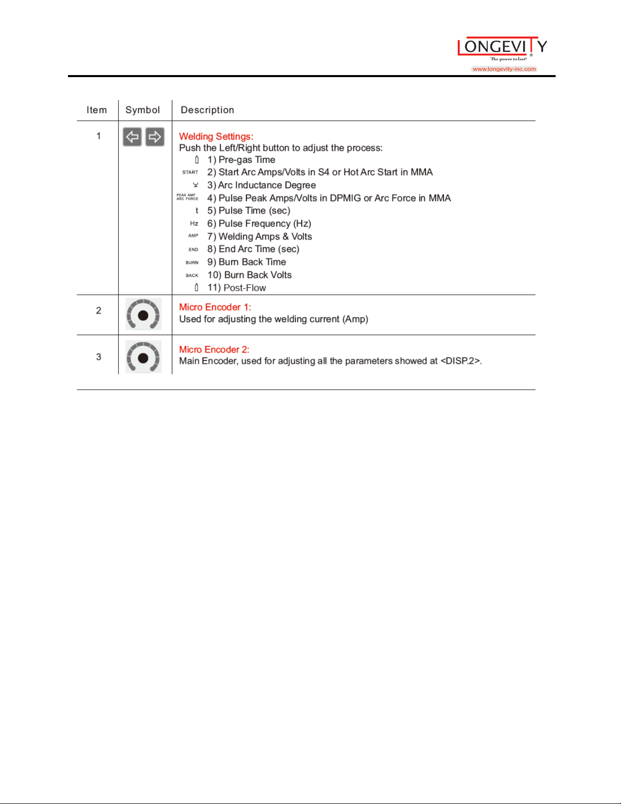
Parameters & Settings
15
Page 17
MIGWELD 250 MP
16
Page 18
MIGWELD 250 MP
2 3 4 7 6
8
1 9 5
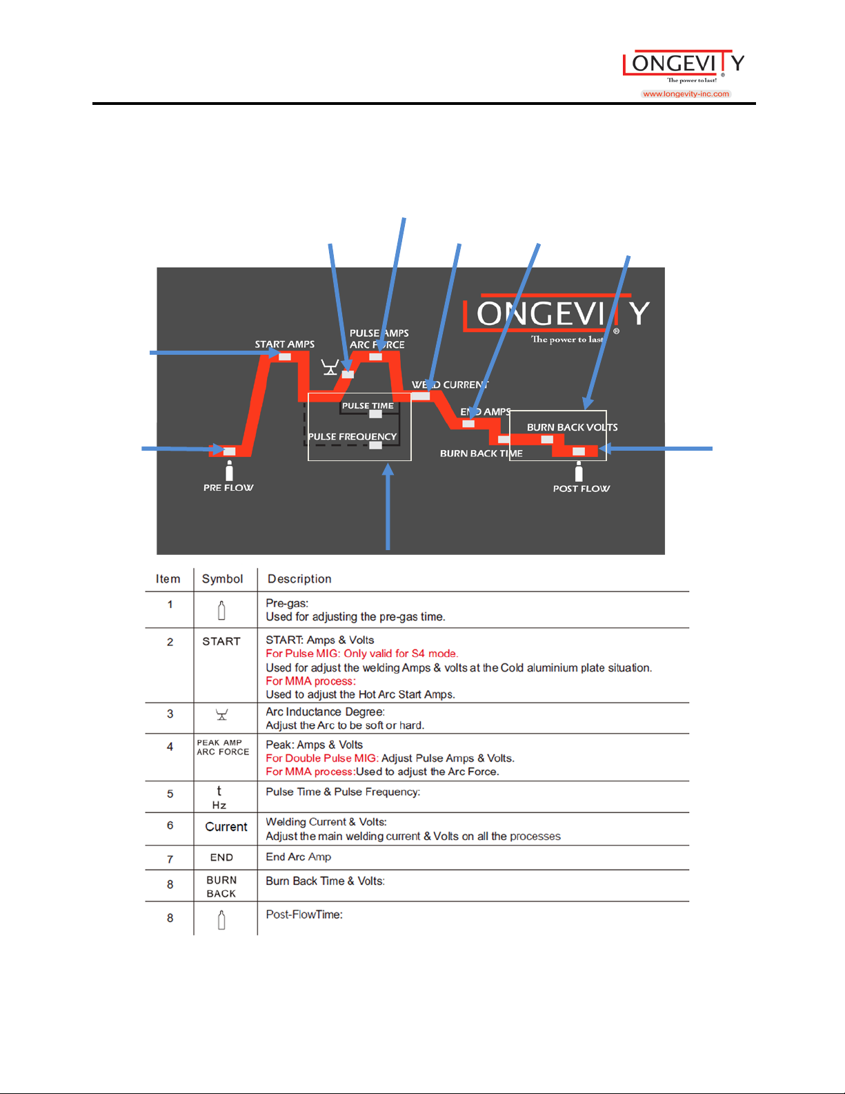
Welding Parameters
17
Page 19
MIGWELD 250 MP
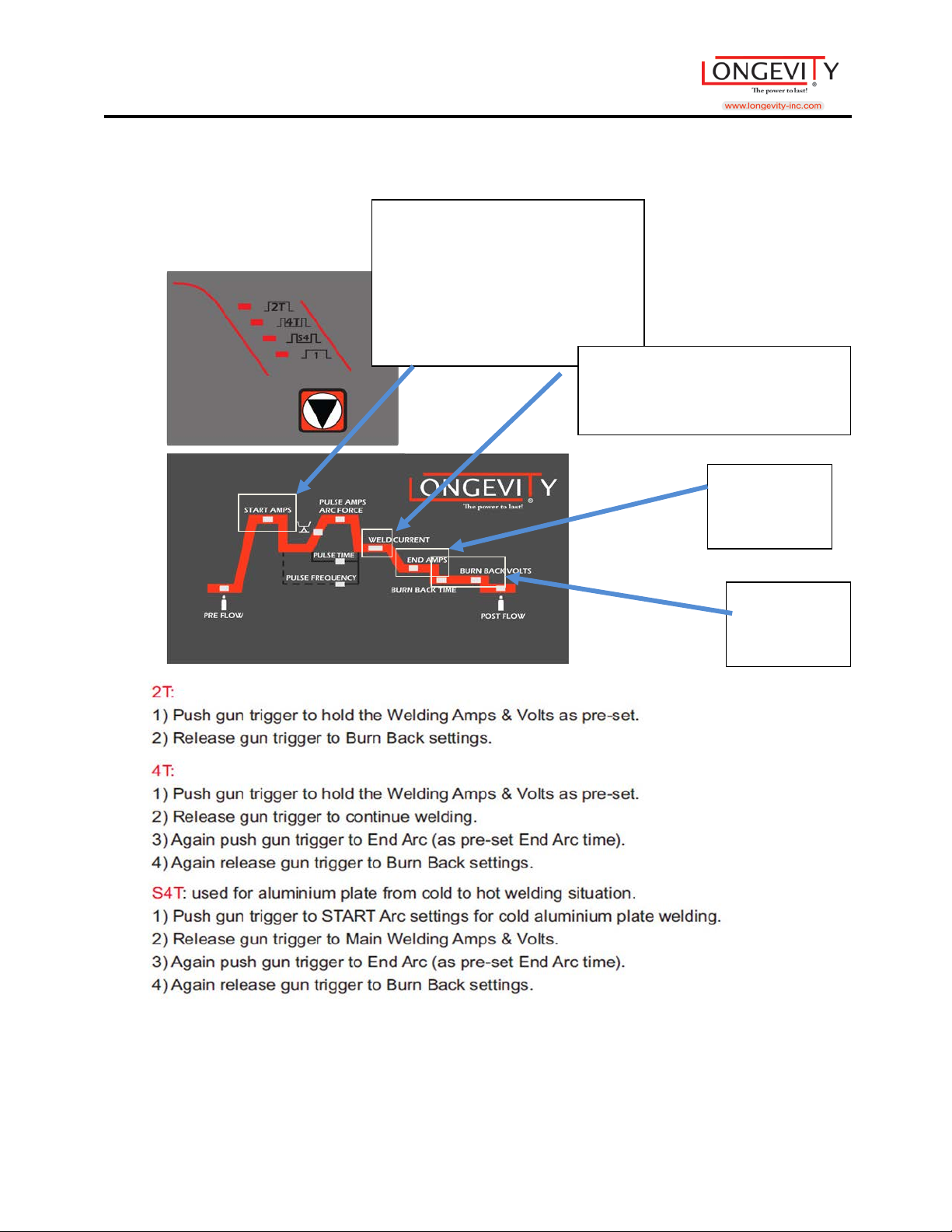
Burn Back
End Amp
Start: Amps & Volts
Welding Amps & Volts
2T/4T/S4T
For Pulse MIG: Only Valid for S4
mode
Used for adjust of welding amps
& volts in a cold aluminum plate
situation.
Adjust the main welding Amps &
Volts on all the processes.
Time &
Volts
18
Page 20
MIGWELD 250 MP
1 2 3
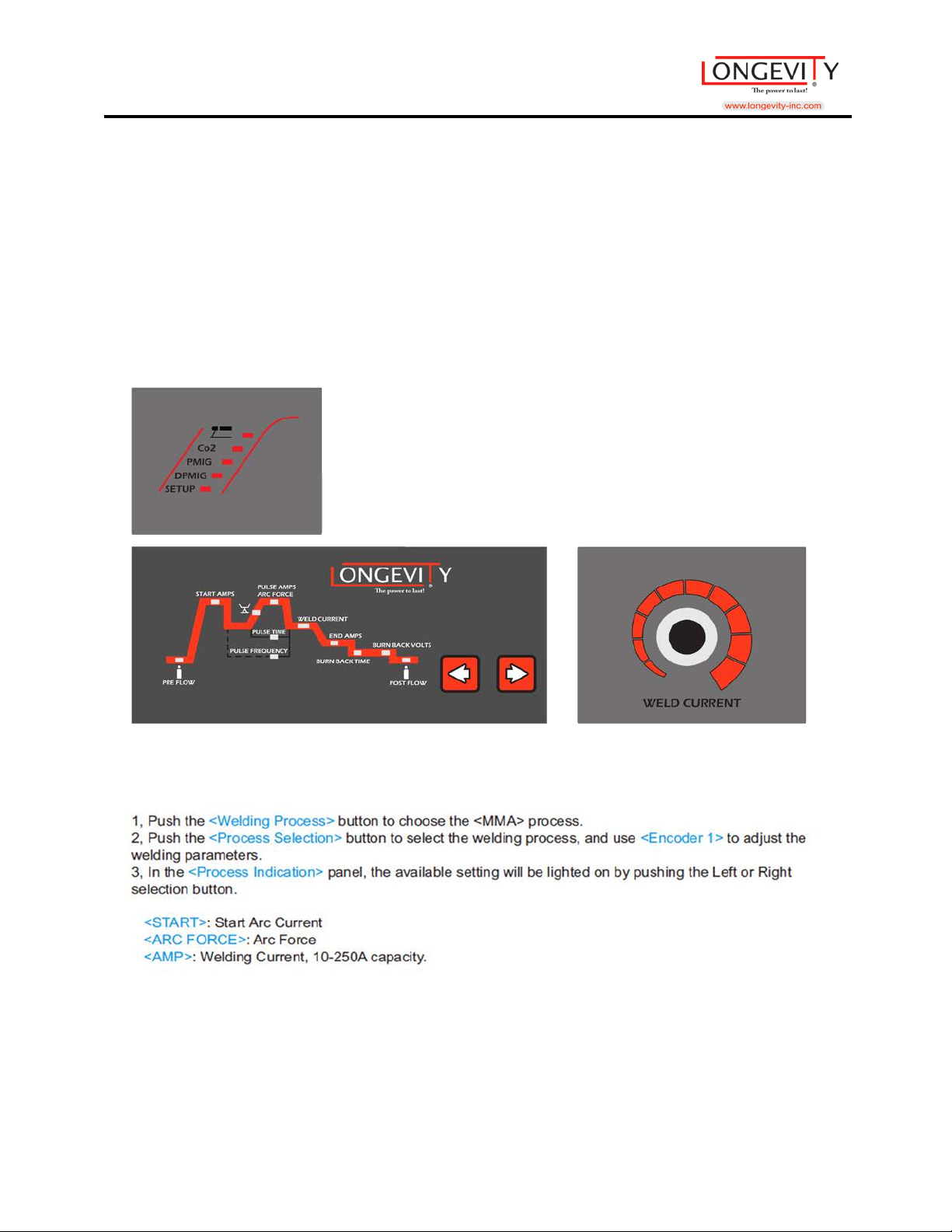
Welding Process
Process Indication
Process Selection
Encoder 1
STICK Process
19
Page 21
MIGWELD 250 MP
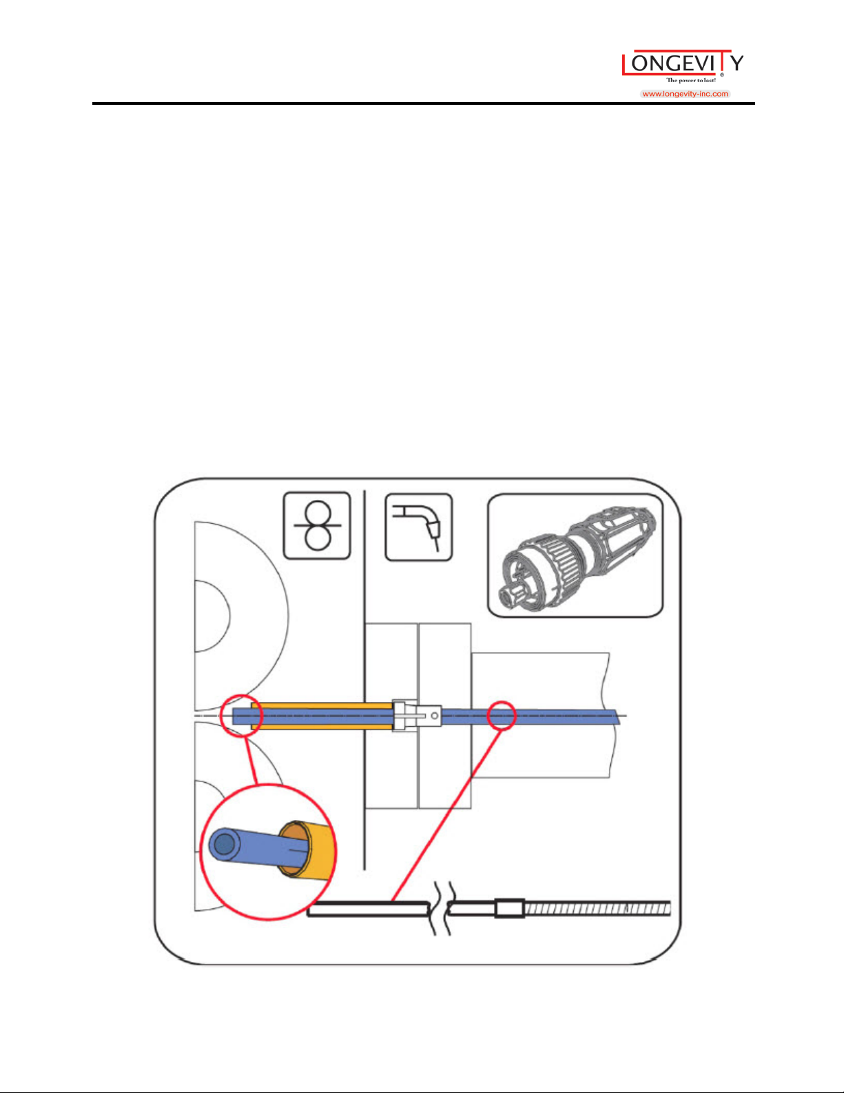
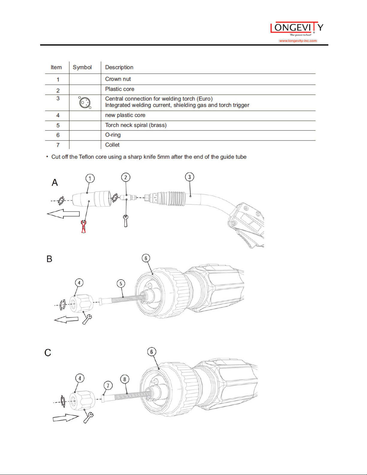
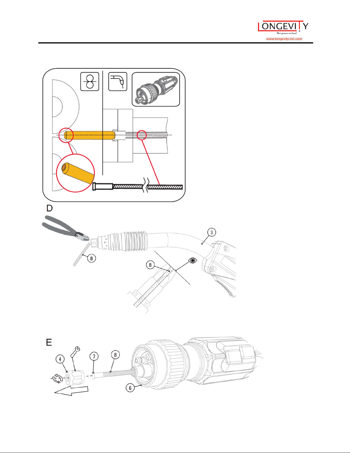
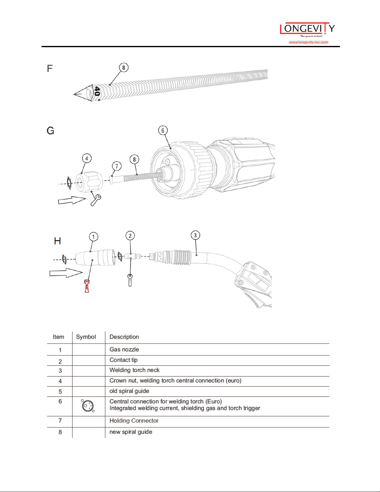
MIG Torch Description
Welding torch and work-piece line connection
Depending on the wire electrode diameter or type, either a spiral guide or plastic
core with the correct inner diameter is inserted into the torch
Recommendation:
• Use a spiral guide to weld hard, unalloyed wire electrodes (steel).
• Use a plastic core to weld or braze soft, high alloy wire electrodes or aluminum
materials.
Plastic Core Diagram
20
Page 22
MIGWELD 250 MP
21
Page 23
MIGWELD 250 MP
22
Page 24
MIGWELD 250 MP
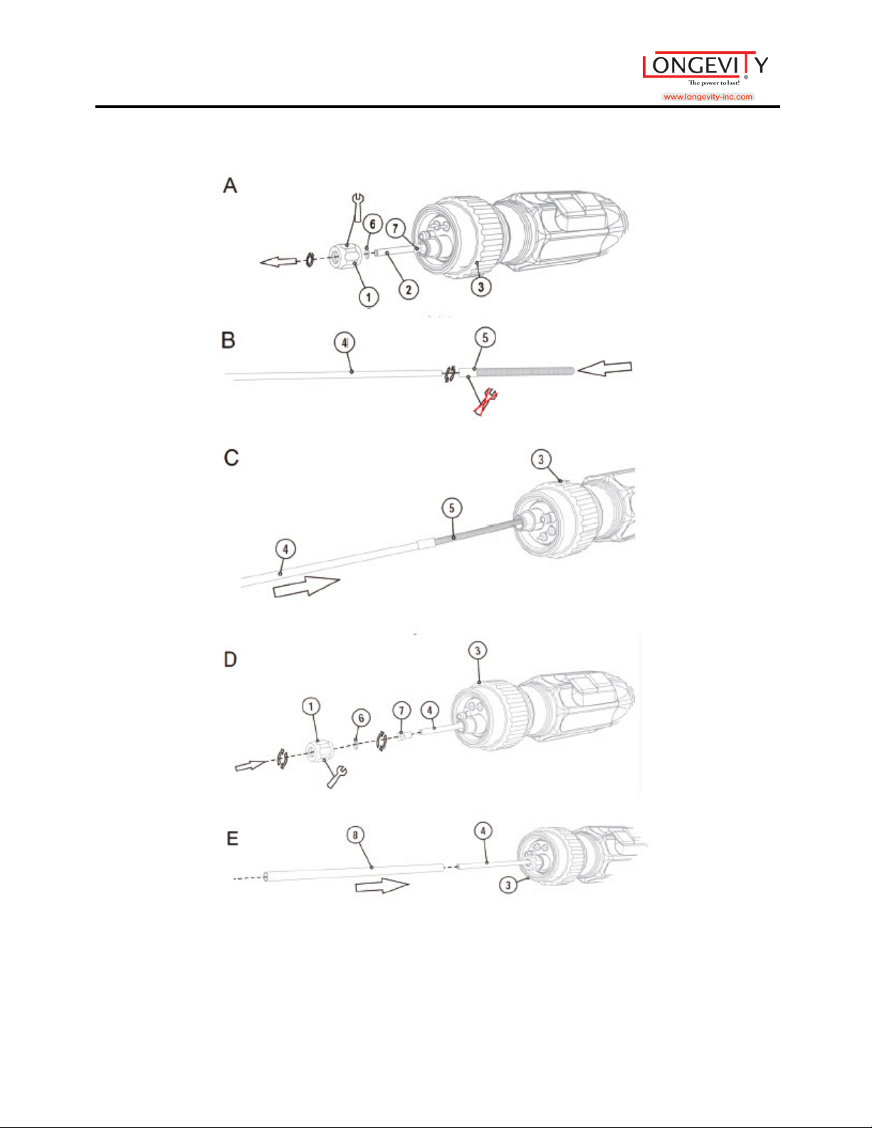
Spiral Diagram
23
Page 25
MIGWELD 250 MP
24
Page 26
MIGWELD 250 MP
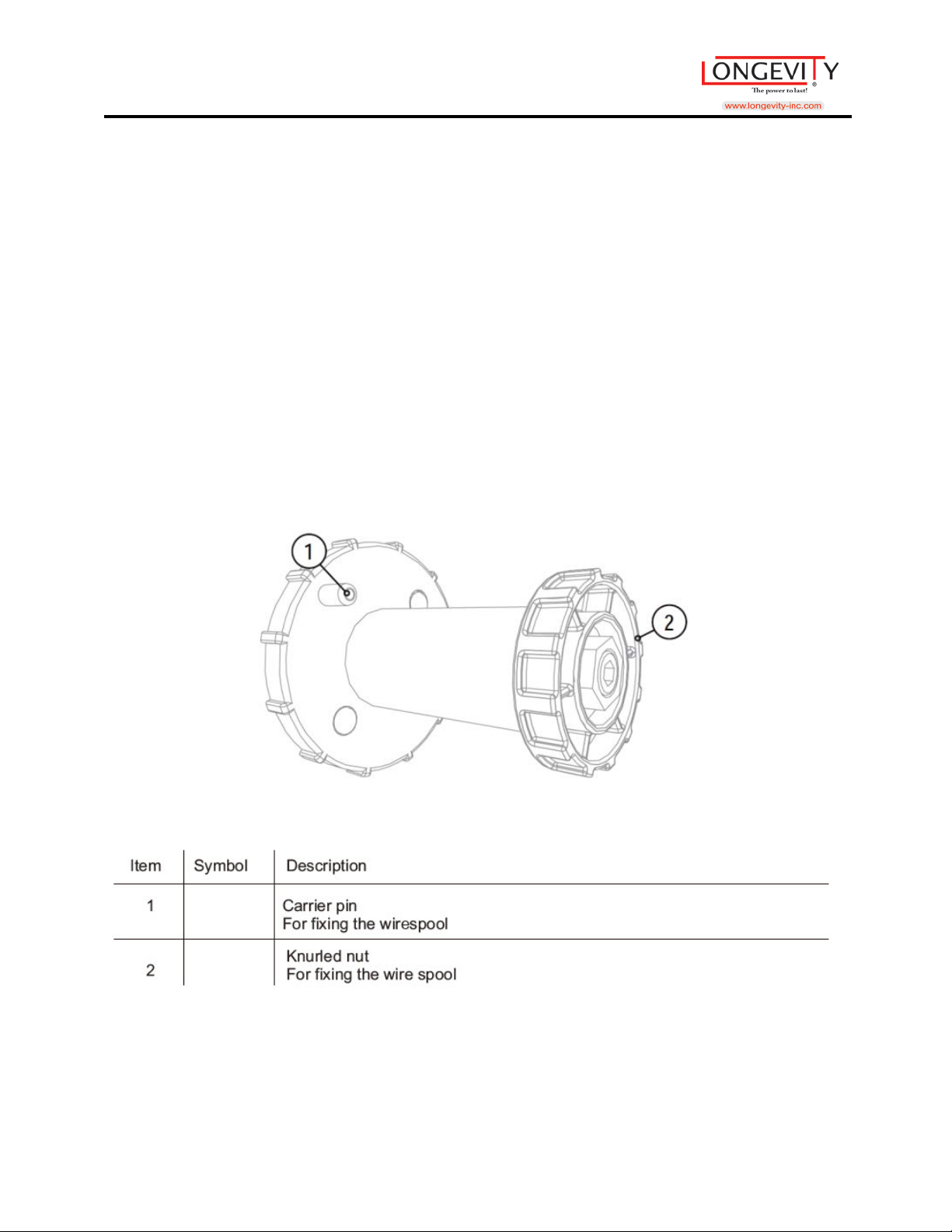
Changing Wire Spool
Removing the Wire Spool
1. Unlock the right-hand cover on the machine.
2. Open the cover, and then remove upwards.
Inserting the Wire Spool
1. Loosen knurled nut from spool holder.
2. Fix welding wire reel onto the spool holder so that the carrier pin locks into the
spool bore.
3. Fasten wire spool using knurled nut.
25
Page 27
MIGWELD 250 MP
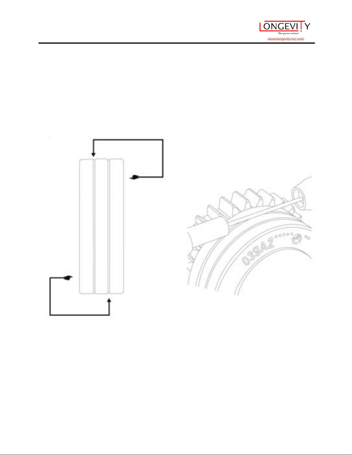
Changing Wire Feeders
1. Slide new drive rollers into place so that the diameter of the wire
used is visible on the drive roller.
2. Screw the drive rollers in place with knurled screws.
26
Page 28
MIGWELD 250 MP
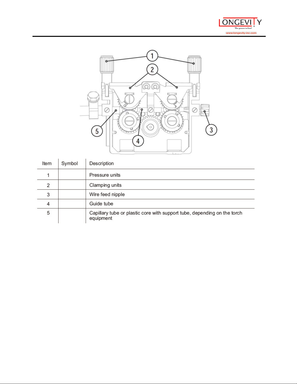
• Extend and lay out the torch hose package
• Unfasten pressure units and fold out (clamping units and pressure rollers will
automatically flip upwards)
• Unwind welding wire carefully from the wire spool and insert through the wire
connector over the drive roller grooves and the guide pipe into the capillary tube
and Teflon core using guide pipe.
• Press the clamping element with the pressure roller back downwards and fold the
wire units back up again (wire electrode should be in the groove on the drive
roller).
• Set the contact pressure with the adjusting nuts of the pressure unit.
• Press the wire inching button until the wire electrode projects out of the welding
torch.
27
Page 29
MIGWELD 250 MP
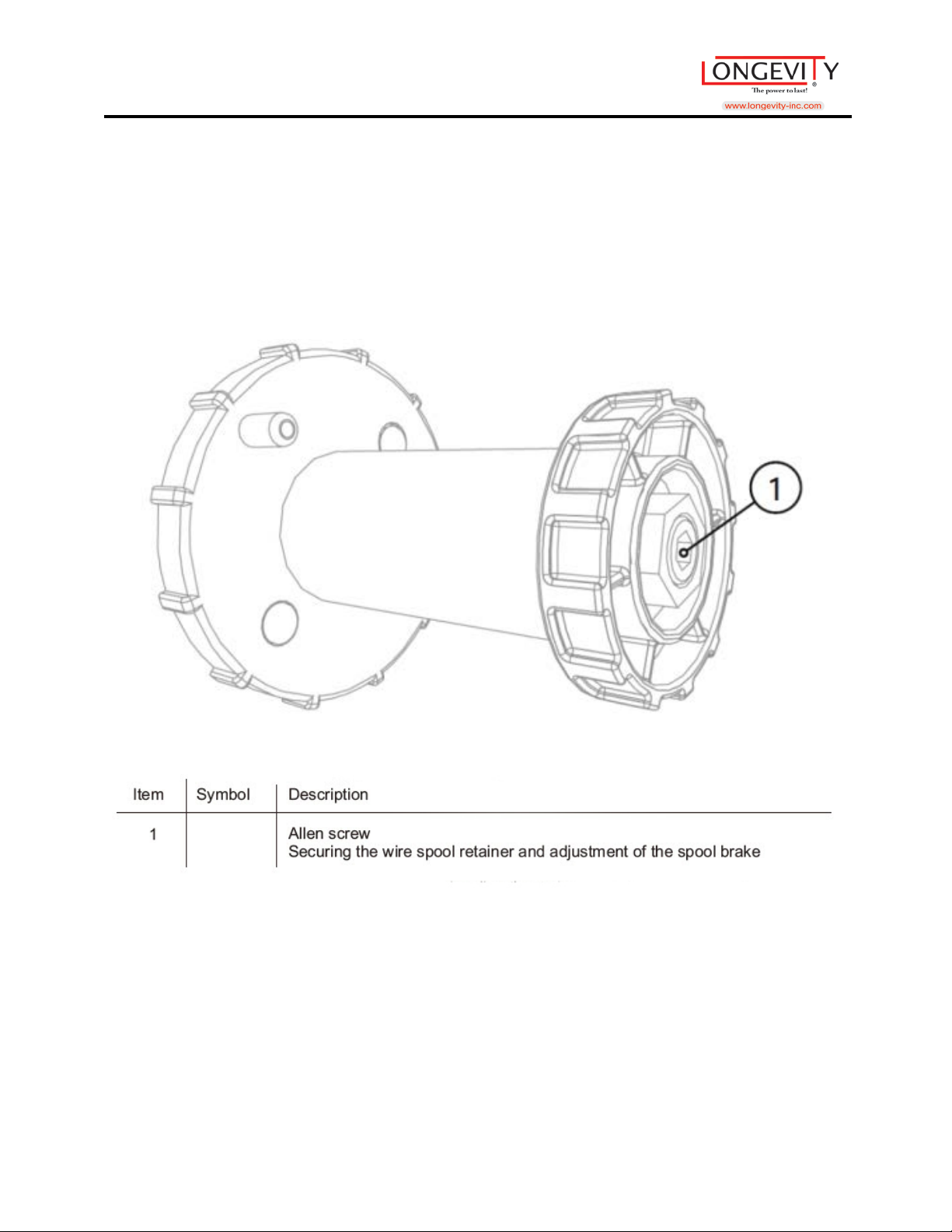
Spool Brake Setting
• Tighten the Allen screw (8mm) in the clockwise direction to increase the
braking effect.
28
Page 30
MIGWELD 250 MP
MIG/MAG/CO2
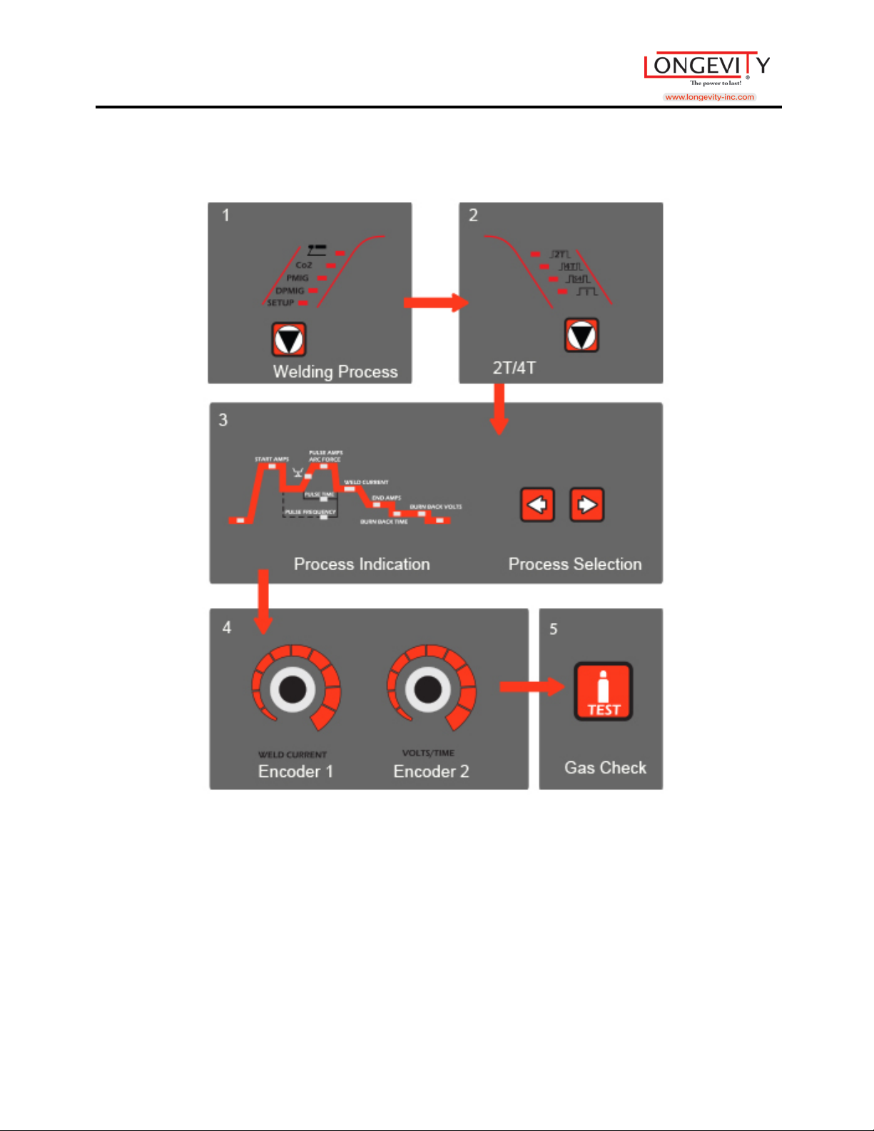
1. Push the <Welding Process> button to choose the <CO2> process.
2. Push the <2T/4T> button to choose hold type of 2T or 4T.
3. Push the <Proc ess Sel ecti o n> button to select the welding process; check the
panel<Process Indication>, the available setting will be lighted on by pushing the
Left or Right selection butt on.
4. Use <Encoder 1> & <Encoder 2> to adjust the welding parameters.
5. Push <Gas Check> button to check the gas before start welding.
<Encoder1> used to adjust the Current (A) showed at <DISP.1>
<Encoder2> used to adjust the Volts (V), Time (S) showed at <DISP.2>
29
Page 31
MIGWELD 250 MP
MIG/MAG/CO2
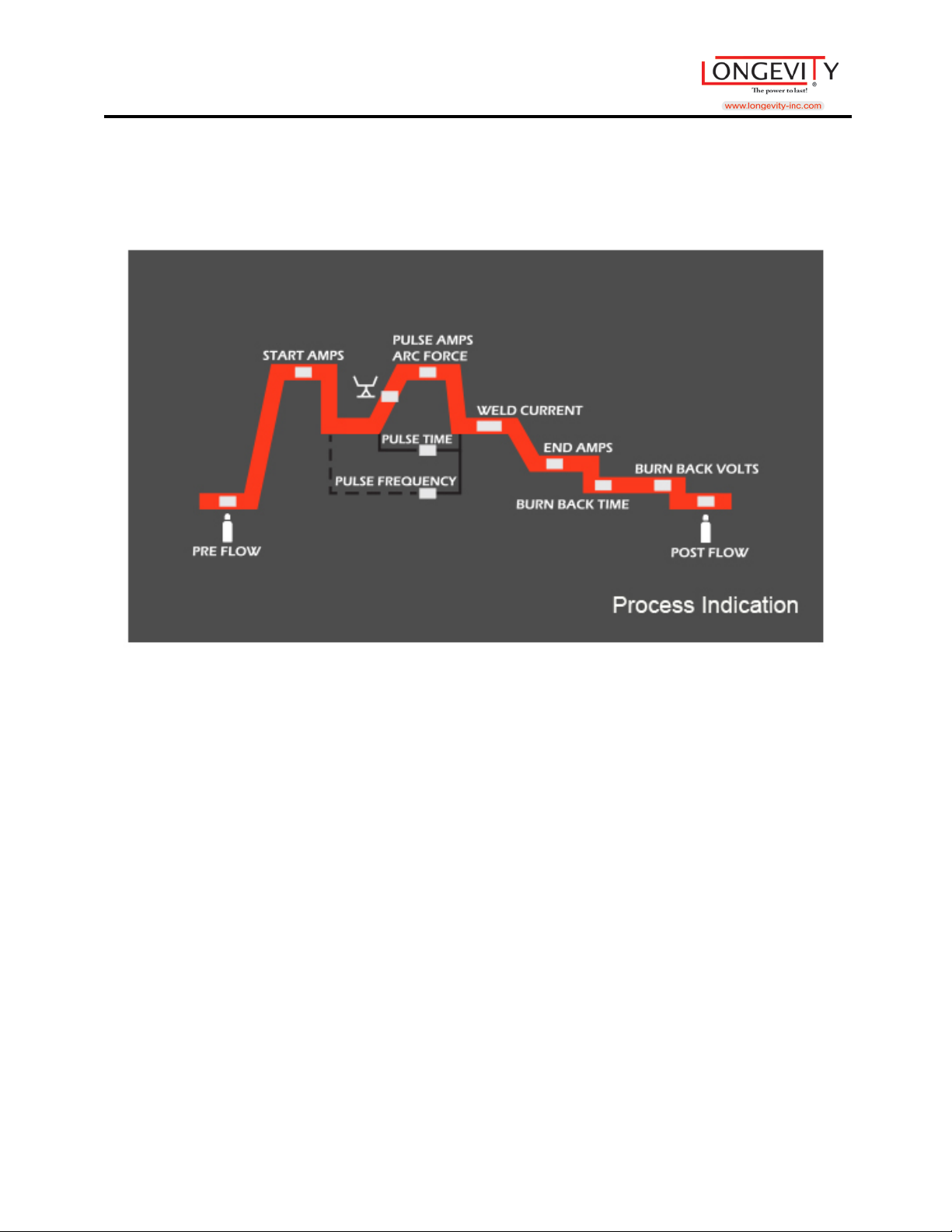
<Pre-Flow> & <Post-Flow>: 0-3.0S
<Arc Inductance Degree>: 1-10
<AMP>: (1) Welding Current, 0-250A
(2) Welding Voltage, 0-26.5V
<End> (1) End Arc Current, 10-250A
(2) End Arc Voltage, 14-26 5V
<Burn Back> Time 0.01-0.5S, Volts 10-25v
30
Page 32
MIGWELD 250 MP
Pulse MIG
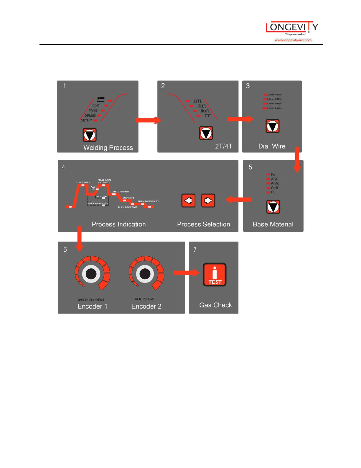
1. Push the <Welding Pr oces s> button to choose the <PMIG> process.
2. Push the <2T/4T> button to choose hold type of 2T or 4T.
3. Push the <Dia. Wire> button to choose the welding wire size.
4. Push the <Base Material> button to choose the welding material.
3. Push the <Proc ess Sel ecti o n> button to select the welding process, check the
panel<Process Indication>, the available setting will be lighted on by pushing the
Left or Right selection butt on.
4. Use <Encoder 1> & <Enc oder 2> to adjus t t he wel di ng para meters.
5. Push <Gas Check> button to check the gas before start welding.
<Encoder1> used to adjust the Current (A) showed at <DISP.1>
<Encoder2> used to adjust the Volts (V), Time (S) showed at <DISP.2>
31
Page 33
MIGWELD 250 MP
Pulse MIG
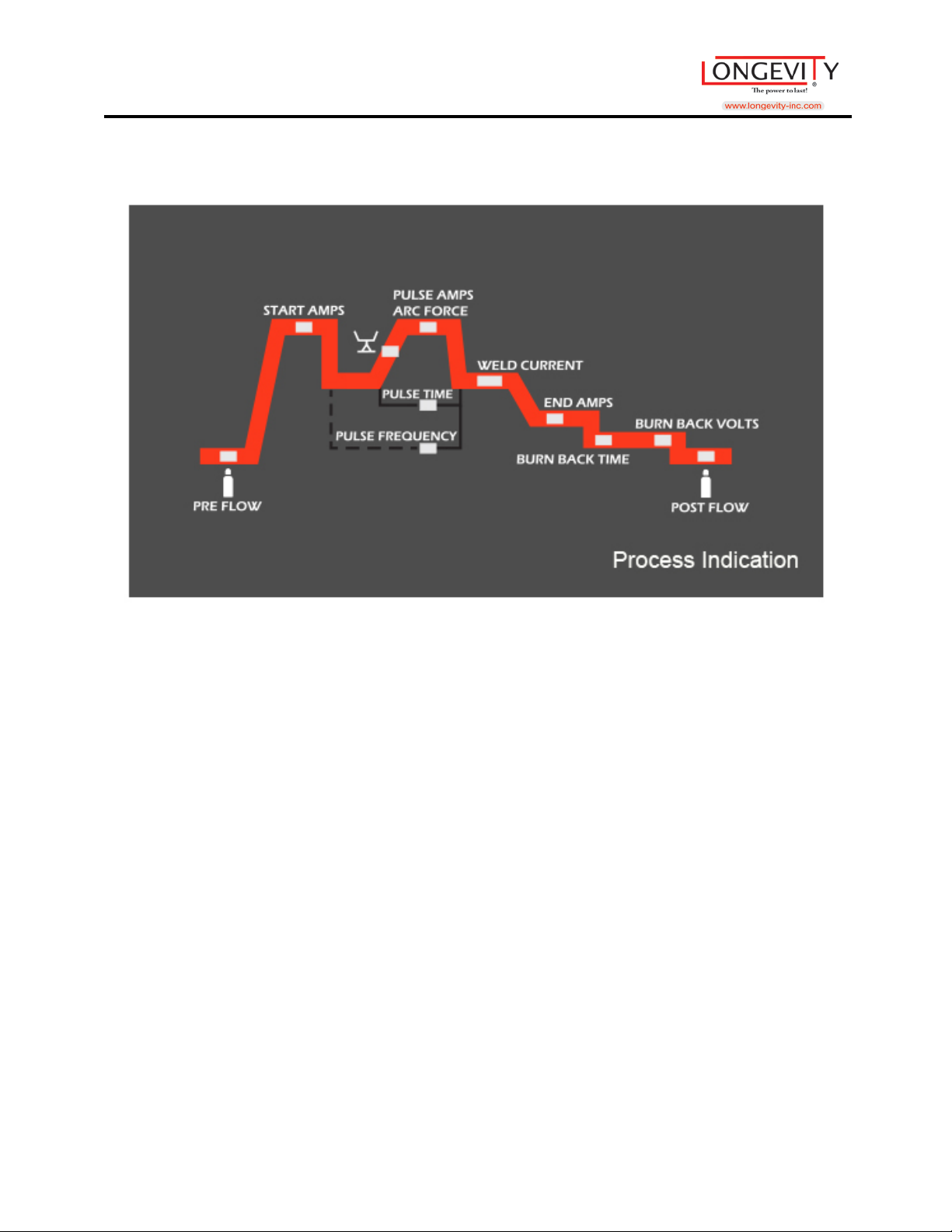
<Pre-Flow> & <Post_Flow>: 0-3.0S
<Arc Inductance Degree>: 1-10
<AMP>: (1) Welding Current, 0-250A
(2) Welding Voltage, 0-26.5V
<End> (1) End Arc Current, 10-250A
(2) End Arc Voltage, 14-26 5V
<Burn Back> Time 0.01-0.5S, Volts 10-25v
32
Page 34
MIGWELD 250 MP
Double Pulse MIG
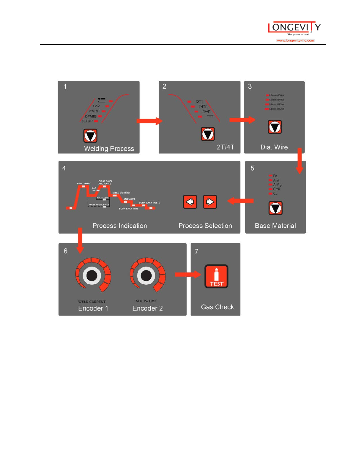
1. Push the <Welding Pr oc ess> button to choose the <DPMIG> process.
2. Push the <2T/4T> button to choose hold type of 2T or 4T.
3. Push the <Dia. Wire> button to choose the welding wire size.
4. Push the <Base Material> button to choose the welding material.
3. Push the <Process Selection> button to select the welding process, check the
panel<Process Indication>, the available setting will be lighted on by pushing the
Left or Right selection butt on.
4. Use <Encoder 1> & <Enc oder 2> to adjus t t he wel di ng para met er s.
5. Push <Gas Check> button to check the gas before start welding.
<Encoder1> used to adjust the Current (A) showed at <DISP.1>
<Encoder2> used to adjust the Volts (V), Time (S) showed at <DISP.2>
33
Page 35
MIGWELD 250 MP
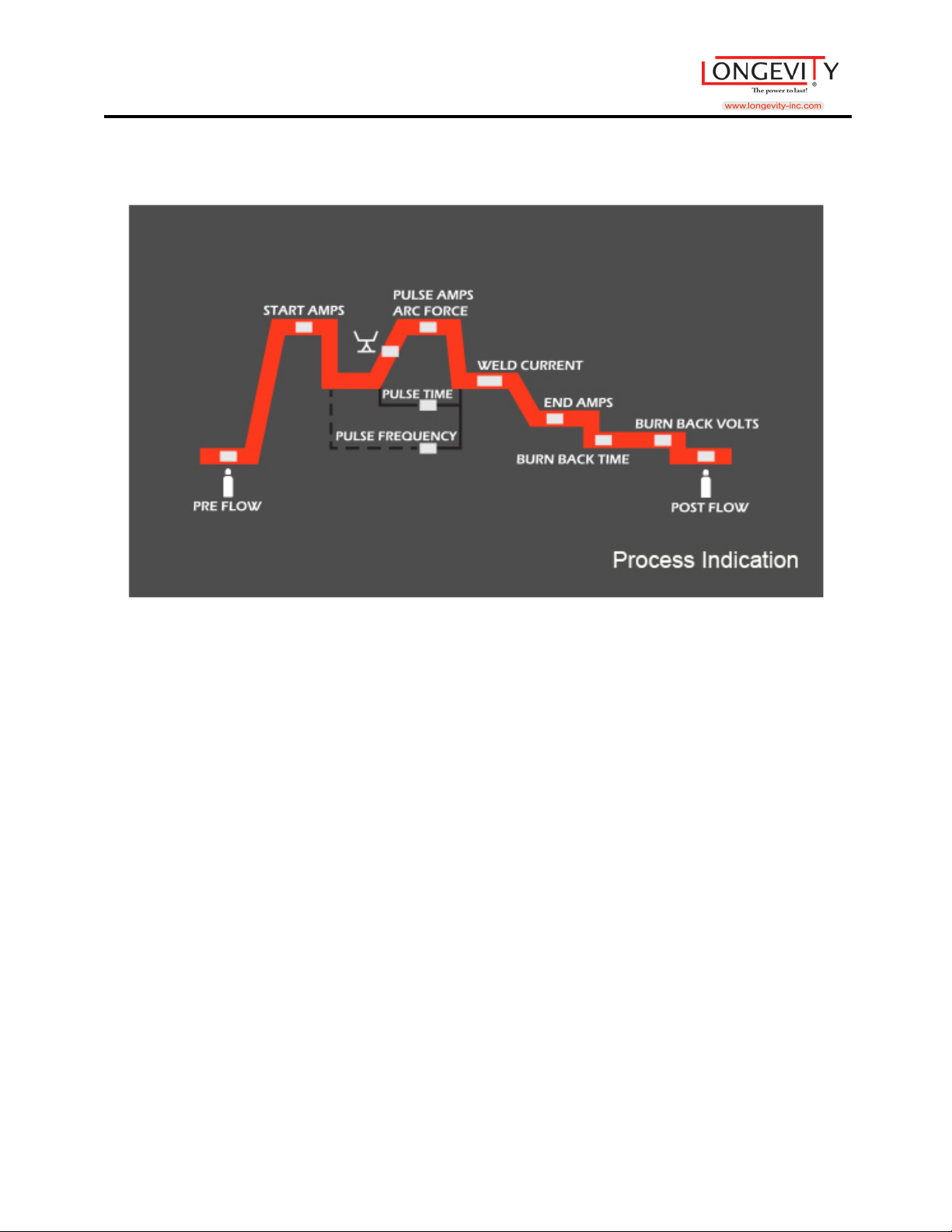
Double Pulse MIG
<Pre-Flow> & <Post-Flow>: 0-3.0S
<Arc Inductance Degree>: 1-10
<AMP>: (1) Welding Current, 0-250A
(2) Welding Voltage, 0-26.5V
<End> (1) End Arc Current, 10-250A
(2) End Arc Voltage, 14-26 5V
<Burn Back> Time 0.01-0.5S, Volts 10-25v
34
Page 36
MIGWELD 250 MP
Store Memory
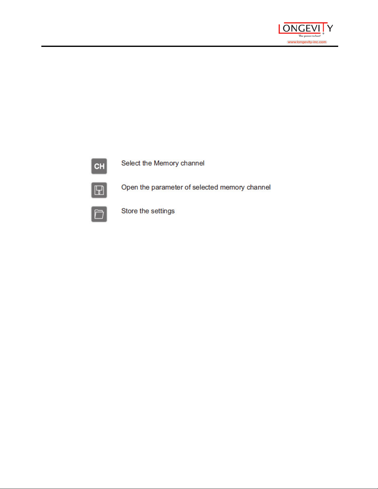
• In the <Memory Settings> buttons you can:
1. Set the welding parameters and store it into memory. The memory
capacity right now is valid to store 10 sets.
2. Select the memory channel for direct welding jobs.
3. Also, you can select a memory channel and open the parameter to make
for fast adjusting from the me mory parameters.
• Also, you can clear all the memories and restore to the factory settings.
1. Push the <Welding Process> button to enter into the <DPMIG> mode and
hold this button at least 5 seconds until the <SETUP> button is lit.
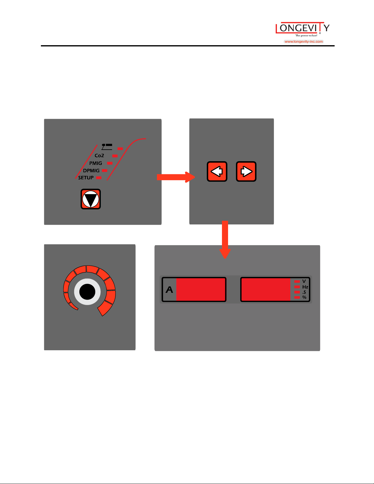
2. Push the Left/Right button on the <Process Selection> and check the
<DISP.2> & <DISP.3> showed “Lod dEF”.
3. Turn the <Endoder 2>, and the <DISP.2> & <DISP.3> will refresh in 2
seconds, and the setting is finished.
4. Restart (Power on) the machine and the memory would be restored to the
factory settings.
35
Page 37
MIGWELD 250 MP
3
7
2
Process
Selection
1
Welding Process
Encoder 2
3
5
DISP 2 DISP 3
4
36
Page 38

MIGWELD 250 MP
Too Short
Normal Too Long
MIG Welding Tips and Tricks
• MIG Welding Tips
1. Direct your wire at the leading edge of your weld pool for the most control of
your weld bead.
2. For the most bead control when doing more difficult welds such as; Vertical,
horizontal, and overhead welds, use the smallest wire diameter possible, and
keep your weld pool small.
3 Your contact tube, gun liner, and drive rolls should coincide with your wire.
4. Keep your gun liner, drive rolls, and gun nozzles clean. Contact tips should be
replaced if there is blockage, or not feeding the way it should.
5. Your gun should stay straight, ensuring the wire will feed properly.
6. Steady the gun with both hands.
7. Do not over tighten wire feeder hub tension and drive roll pressure.
8. Store your wire in a place that is contaminant free.
• Elec trode Tip Length
Never let you electrode’s distance from your contact tube exceed ¼” to ¾”. If you
do your weld will not be correct.
37
Page 39
MIGWELD 250 MP
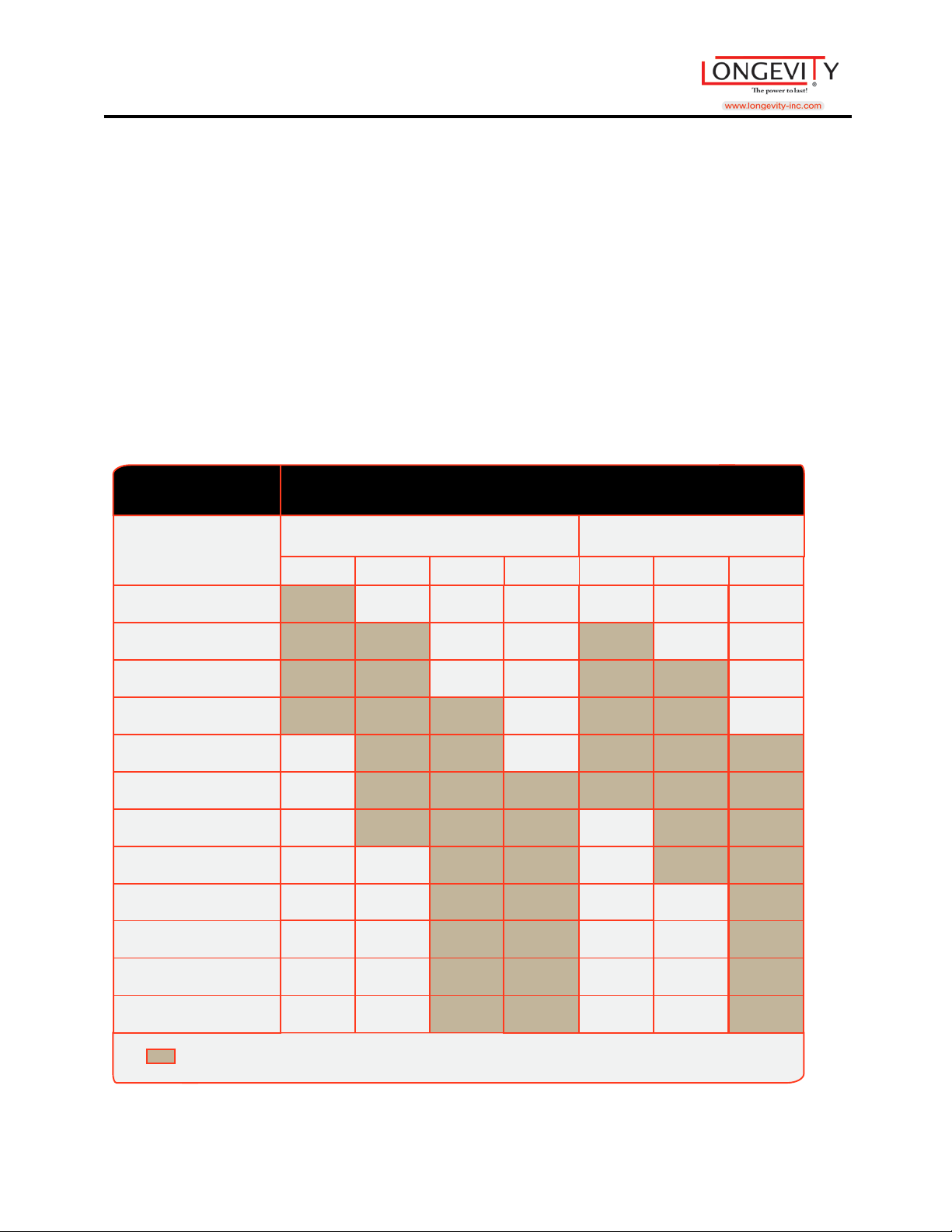
RECOMMENDED WIRE SIZES
MIG Solid Wire Gasless Flux-Core Wire
Material
Thickness
24 Gauge (.025)
22 Gauge (.031)
20 Gauge (.037)
18 Gauge (.050)
16 Gauge (.063)
14 Gauge (.078)
1/8” (.125)
3/16” (.188)
1/4” (.25)
5/16” (.313)
3/8” (.375)
.024”
1/2” (.5)
.030” .035” .045” .030” .035” .045”
= Recomended
*When welding materials that are thicker than 3/16” you may need to use Multi pass or welding, or beveled joint design (depending on your machine)
.
= Recomended
• Welding Wire
Thin Metal= Thin Diameter.
Thick Metal= Larger wire, with a larger machine.
Use the wire that matches your metal.
Don’t use aluminum with stainless, or vice versa
38
Page 40

MIGWELD 250 MP
WELDING WIRES
Shielding gas- C02 or 75%Argon/25%
CO2 is recommended and will give you deeper penetration
75%Argon/25% will give you less splatter and a nicer
lookingbead
Should be used indoors, where wind cannot harm your weld.
Allows you to weld materials thinner than what you would
weld with flux cored wires
Great for auto body work
.
Shielding gas- not needed
Can be used outside, wind will not harm your weld
Great for use on aged or rusty metals
Burns hotter than solid wires, allowing for welding of
materials thicker than 18 gauge
.
Shielding gas-Argon only
Should be used with a spool gun
Gives you a strong weld
.
Shielding gas- Trimix
Use on stainless metals 301-305 and 308
.
Solid
Carbon-Steel
ER70S-6
Aluminum
ER5356
Flux Cored/
Carbon-Steel
E71TGX
Stainless Steel
ER308L
39
Page 41
MIGWELD 250 MP
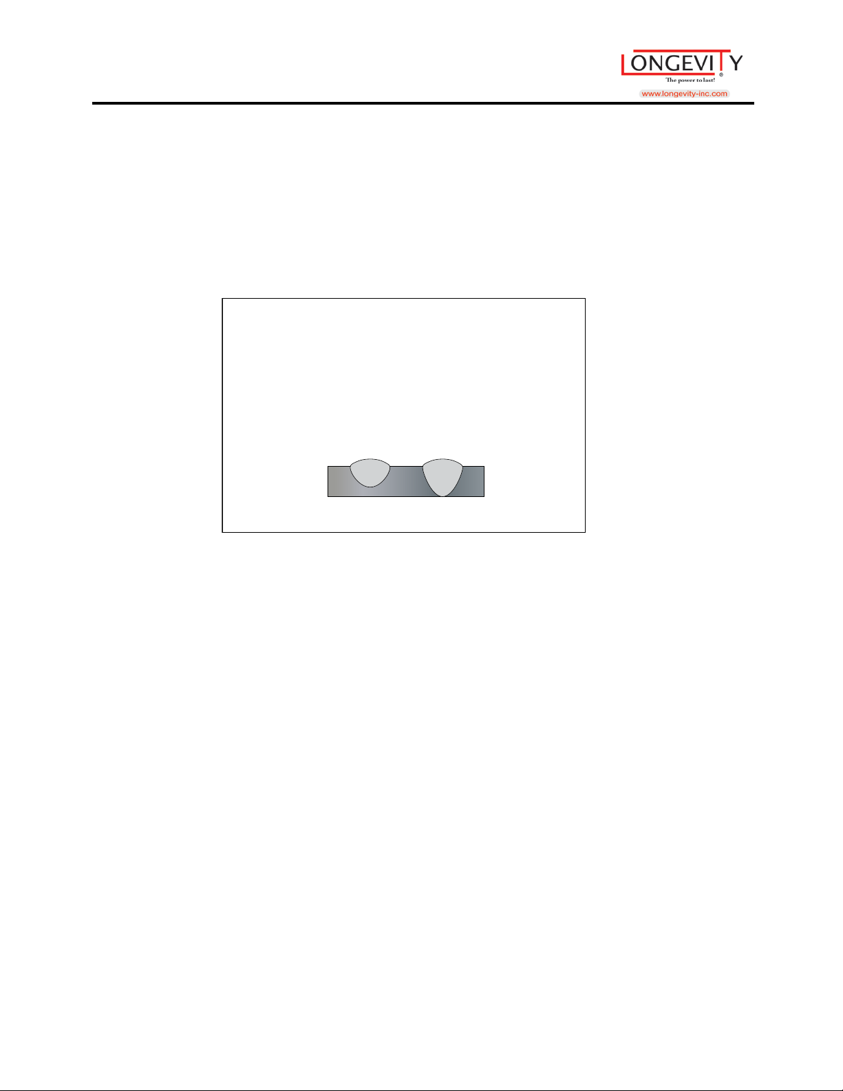
Argon + CO CO
2
2
Steel Penetration Patterns
• Shielding Gas
Co2 should be used with thick materials, but is too hot for thinner materials.
Thin steel sho ul d be welded with 75% Argon/25% Co2.
Aluminum should be welded with Argon.
Stainless steels can be welded with a triple-mix, or Helium+Argon+Co2
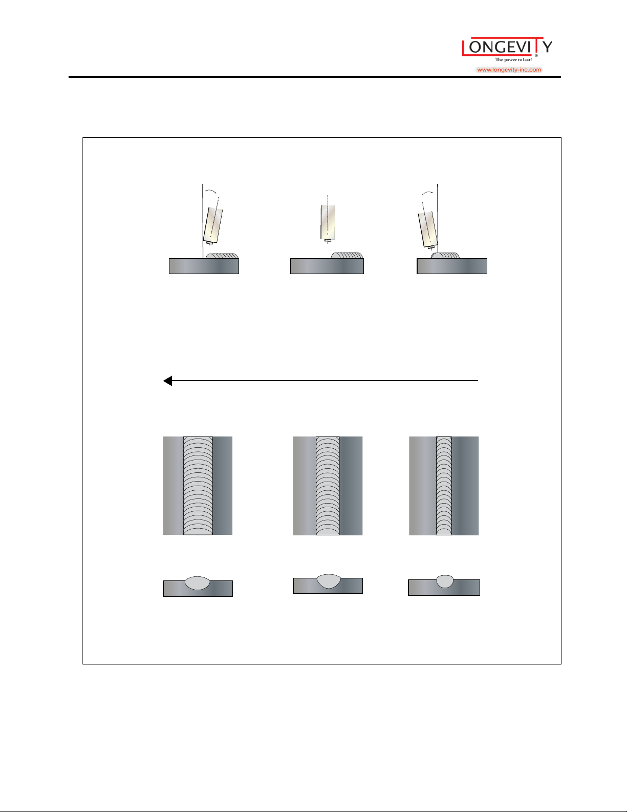
• Gun Techni ques
Drag/Pull= More penetration with a more narrow bead
Push= Less penetration with wider bead
40
Page 42
MIGWELD 250 MP
Welding Di rection
(A) Push
Technique
(B) Gun
Perpendicular
(C) Drag- Pull
T
echnique
10
º
Electrode
ahead of bead
Push
10
º
Electrode
back into bead
Drag
Perpendicular
41
Page 43
MIGWELD 250 MP
A
A
B
B
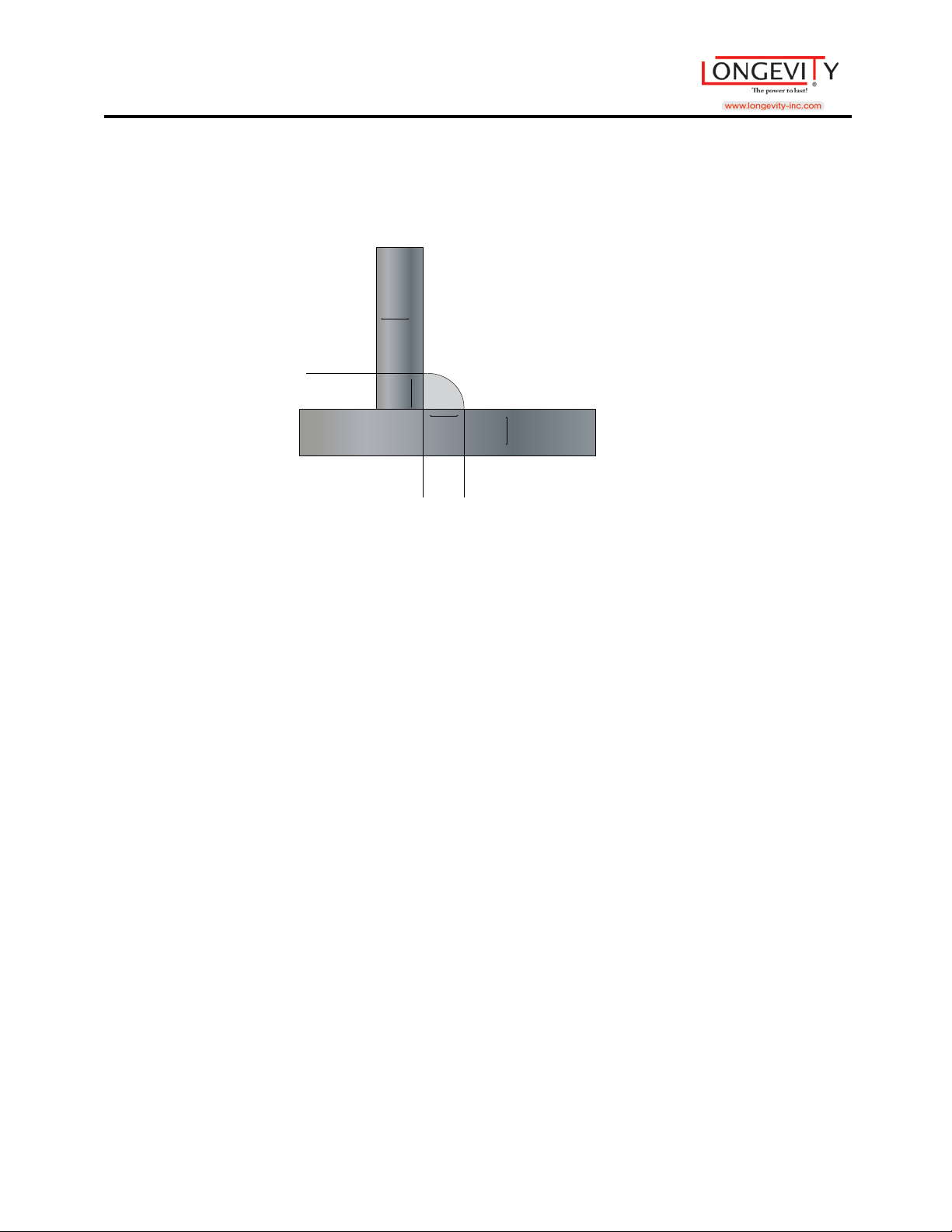
• Fillet Welds
The leg of your weld should be equal to the thickness of the materials you
welded.
• Aluminum MIG Welding Tips
• It is highly recommended to use a spool gun when welding with aluminum.
However, if you don’t have access to one, you can try using an extremely short
gun.
• Keep your gun straight.
• Use Argon as your shielding gas
• Push gun away from you as you weld (Push gun technique)
• Feeder Problems? A possible solution to feeder problems is using a contact tip
that is one size larger than your wire.
• ER403 wire can be used for most projects. ER4356 should be used when your
weld needs to be stronger, or rigid.
• Always clean your aluminum before welding, using a stainless steel wire brush.
This brush should only ever be used for cleaning aluminum wire to prevent
contamination.
42
Page 44

MIGWELD 250 MP
• Fill the crater at the end of the weld to avoid a crack. One way to do this is to
dwell in the weld pool for a second at the end of the weld.
• Wh y Choose A Spool Gun?
• Spool Guns are recommended to be used while welding aluminum. There are
many benefits to using a spool gun on aluminum over your standard MIG torch,
which include:
• Using a spool gun prevents you from contaminating aluminum with a gun that
had been used with previous metals, ensuring the highest quality weld.
• Aluminum is more delicate of a metal. Spool guns have a far less distance to be
fed through, whic h me ans less chances of the aluminum kinking.
• Aluminum needs to expand as it comes out of the contact tip. The diameter of a
spool gun contact tip is much bigger than that of a MIG gun, giving the aluminum
the room it needs.
• Self-Shielded Flux Cored W elding Tips
• Pull torch away from you as you weld (Pull gun technique)
• Store your wire in a dry place free of contaminates
• Use a chipping hammer and wire brush to remove slag layer after weld is
complete
• You do not need shielding gas—Great for welding outdoors!
• You won’t be able to weld as thin of metals than would with normal MIG
welding.
43
Page 45

MIGWELD 250 MP
STICK Welding Tips and Tricks
(Also known as MMA-Manual Metal Arc or Shielded Metal Arc Welding-SMAW)
Connect the Stick torch to the - terminal and Torch Control receptacles.
Connect the ground clamp to the + terminal and clamp the metal to be welded. Reverse the
torch and ground connections for DCEP (Direct Current Electrode Positive).
DC Stick - Select Stick, DC, desired amps using Base cur knob, Pulse Mode off.
1. Insert electrode into electrode holder. Position the electrode for the most comfortable
position so that the electrode can be held directly over the work piece with a slight angle.
2. Set Amperage to the recommended amperage by the electrode manufacturer. Strike an arc
by swiping it briskly across the work piece in the same manner as one would strike a match.
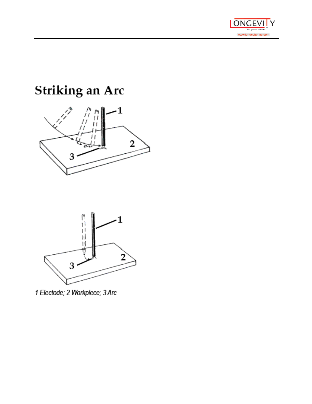
Alternatively, you may strike an arc with firm tapping motion against the work piece. Either
method is acceptable. An arc should initiate. Continue to keep the arc going by holding the
electrode off the work piece no more than the electrode width.
3. Continue the arc by feeding the electrode into the weld puddle while moving the electrode
forward. This will take some coordination, but will be fairly easy to do after practice. Do not
allow the arc to become too long, because air and slag can become entrapped in the metal. The
sound of a proper arc will be similar to a gentle frying sound. A long arc will emit a humming
sound. An arc that is too short may be extinguished and the electrode may stick to the work
piece. If the electrode sticks, immediately release the electrode from the electrode holder and
break the electrode loose by hand. If the flux breaks off, simply trim off the excess rod until
flux and bare metal meet. A welding rod must have flux to shield the weld from the
44
Page 46

MIGWELD 250 MP
atmosphere or the weld will fail.
4. Use the Current control to change arc qualities. Adjust the amperage according to the
recommendations of the electrode (welding rod) manufacturer for the type and size of the
electrode used. Experimentation will be required to find the optimal setting desired. It is an
excellent tool for out of position welding.
5. Electrode selection. Electrodes are usually given performance and characteristic ratings
using a system of letters and numbers determined by the American Welding Society (AWS).
The rating system includes the minimum tensile strength of the finished weld, the weld
position (flat, vertical, horizontal, or overhead or a combination of two or more positions) and
the flux type. Additional information may be given. Each manufacturer has their individual
name and terminology as well.
As there is no general recommendation that can be made about a particular electrode selection,
except for practice welds, a electrode designated by the AWS as E 6011, E 6013, E 7014, or E
7018 may be used, each having its own distinct features and purpose. These are among the
most common electrodes used in the industry and are not difficult to find. E 6011 electrodes
are not as smooth running as some of the other electrodes, but offer the advantage of being
able to weld on rusty metal and contaminated surfaces. It is widely used and requires very little
skill to begin using. This is not a particular endorsement of an E6011, rather a simple example
of what may be used in developing proficient technique. It is recommended that a variety of
electrodes be used and practiced with. Consultation with an experienced local welding supplier
will help greatly in determining what welding electrode is the best for your given situation.
Many times, samples or small packages of electrodes are available at relatively low cost.
45
Page 47

MIGWELD 250 MP
Stick Electrode Chart Example: E 60 1 3
Strength
60--60,000 psi,
70--70,000 psi
Weld Position
1--All positions: Flat, Vertical, Horizontal, & Overhead
2--Flat Position or Horizontal Fillets Only
3--Flat Position Only
Weld Characteristics
0--Non-low hydrogen, DC Reverse polarity
1--Non-low hydrogen, AC or DC Reverse polarity
2--Non-low hydrogen, AC or DC Straight polarity
3--Non-low hydrogen, AC or DC Either polarity
4--Non-low hydrogen, iron powder coating, AC or DC Reverse polarity
5--Low-hydrogen, DC Reverse polarity
6--Low-hydrogen, AC or DC Reverse polarity
7--Non-low hydrogen, iron powder coating, AC or DC Reverse polarity
8--Low hydrogen, iron powder coating, AC or DC Reverse polarity
Polarity Definition
electrode negative =straight polarity (typical stock machine setup)
electrode positive = reverse polarity
Be sure to observe the electrode manufacturer recommendations regarding polarity. If the weld
appears lumpy, porous or otherwise malformed, change the polarity of the ground cable and the
electrode holder cable. Many electrodes run with in reverse polarity, (DCEP) setting. A few run
with a straight polarity (DCEN). Some will run either way. For reverse polarity (DCEP) stick
welding, swap the electrode holder and ground cable connections.
46
Page 48

MIGWELD 250 MP
Proper weld identification: Overlap and undercutting are two main causes of weld failure. Proper
washing of the weld bead into the sides or “toes” of the weld is important. Keep the welding
electrode or the TIG tungsten and welding arc within the weld joint to prevent overlap. Pausing on
the sides of the welds to wait for the sides to fill reduces the chance of undercutting, even if the
current is a little too high. If it is possible, with any practice weld, cut the joint down the middle,
lengthwise, or place the weld in a vice and use a hammer to bend the metal over the weld area until
it is either broken or bent 90 degrees. This destructive testing method will help you improve your
skill by revealing faults and flaws in your welds.
Stick (SMAW) Electrode Welding
Stick, the most basic of welding processes, offers the easiest option for joining steel and other
metals. Although it produces the least pretties or cleanest welds, ARC/STICK welding gets the
job done! Stick welding power sources deliver inexpensive options for welding versatility,
portability and reliability. Stick joins metals when an arc is struck between the electrode and the
work piece, creating a weld pool and depositing a consumable metal electrode into the joint. The
electrode's protective coating also acts as a shielding gas, protecting the weld and ensuring its
purity and strength. Best for windy conditions and adverse environments.
If you’re not familiar with Stick (SMAW) welding basics, the following information can
make choosing an electrode easier.
47
Page 49
MIGWELD 250 MP
48
Page 50
MIGWELD 250 MP
49
Page 51
MIGWELD 250 MP
Helpful Hints
•
Use a drag technique for most applications.
Take precautions with flying materials when
•
chipping slag.
Keep electrodes clean and dry - follow
•
manufacturer instructions.
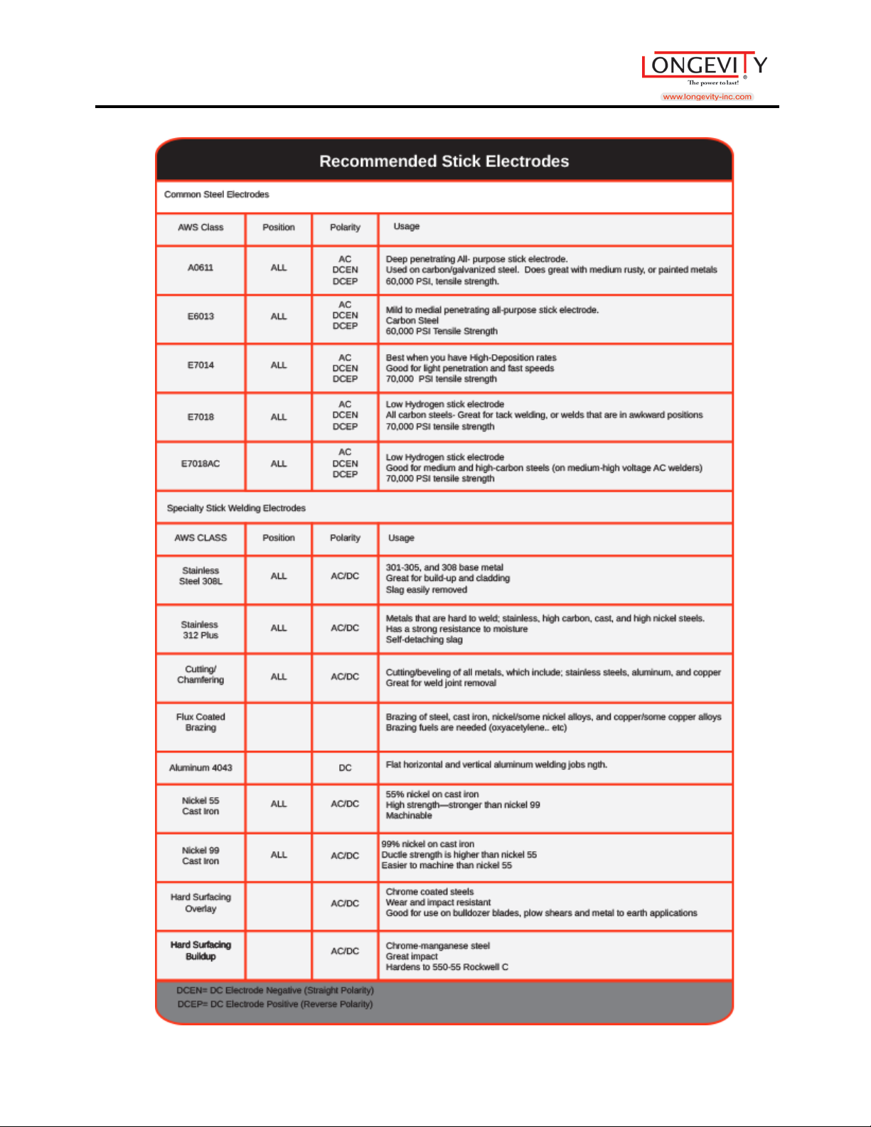
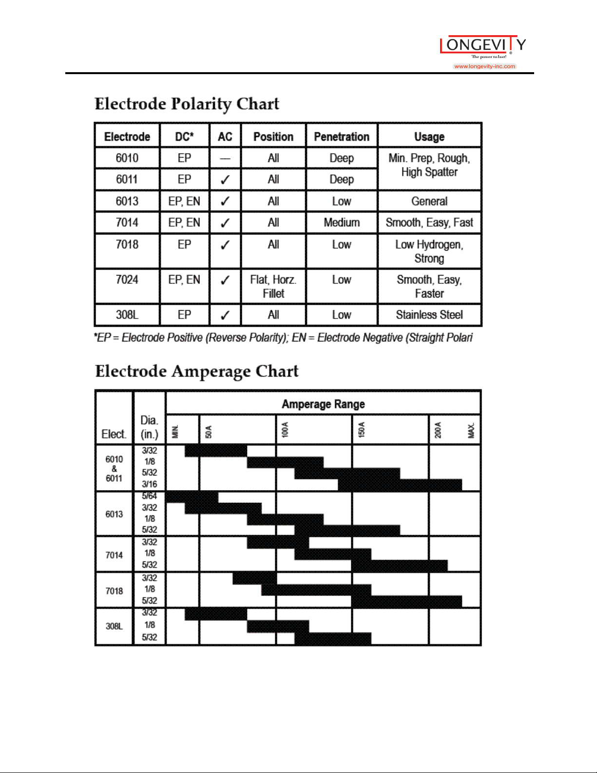
Common steel electrodes (refer to chart
•
above).
• Penetration: DCEN- Less penetration; AC -
Medium (can be more spatter also); DCEP Most penetration
Catalog and Capabiliti es
LONGEVITY has what you n ee d for stick we ld i ng, from
welders to welding supplies and p rotective clothing. Stick
welders come in two basic classifications; 115V stick
welders and 230/460V stick welders. Stick Electrodes or
welding rod for stick welding ar e a vailable in stainless
steel, carbon steel, low alloy steel, maintenance alloy,
hard facing, nickel alloy, and magnesium
50
Page 52

MIGWELD 250 MP
Routine Maintenance
The life of your machine and the quality of the work performed using your machine, will be
enhanced by practicing periodic routine maintenance.
• At re gular intervals, clear dust that may accumulate in the mach ine using clean and dry
compressed air. If the working condition has heavy smoke and pollution, the welding
machine should be cleaned once a month.
• Keep the machine exterior clean with a damp rag.
• Do not walk on or store items on the cables or cords.
• Do not jar, drop, or stack items on top of the machine.
• Always connect the machine to a proper grounded electrical outlet.
• Always check the torch consumables before and after use and ensure that the y are cle ar o f
obstructions, and that no parts are damaged.
• Replace any worn or damaged consumables before using machine.
• For periods of prolonged non-use, remove cables and store them in their original boxes in
a cool dry place, free of bug infestation.
51
Page 53

MIGWELD 250 MP
LONGEVITY® Global, Inc. thanks you for your purchase and the opportunity to be able to
serve you. If, after reviewing this manual, you have any problems in setting up or operating
your machine, contact us at [email protected].
LONGEVITY® Global, Inc.
Toll-Free 1-877-LONG-INC / 1-877-566-4462
Website: www.longevity-inc.com
Sales: [email protected]
Customer Service: [email protected]
Dealers: [email protected]
Please join our welding forums to share welding tips and tricks, to receive useful information
from customers who also use our products, and to be a part of the LONGEVITY® welding
community at www.freeweldingforum.com
For the coolest LONGEVITY sponsored race teams plus a complete racing forum that covers
everything from Drag Racing to RC Car Racing, please check out www.longevity-racing.com!
Enjoy your new welding machine from LONGEVITY! Thanks again!
52
 Loading...