

Page 1

Operating Manual
For
160 and 205
IGBT MIG Welder/ARC Welder
Page 2

160/205 MIG Welder/ARC Welder
Table of Contents:
PG. 2:
PG. 3-4:
PG. 5-7:
PG. 8:
PG. 9:
PG. 10-11:
PG. 12-13:
PG. 14-18:
PG. 19:
PG. 20:
PG. 21:
PG. 22:
Thank you From LONGEVITY
Warranty/Shipping Damage/Order Information
Warning and Safety Information
General Description
Specifications and Ratings
Recommended Optional Accessories
Main Unit Knob/Button/Function
Welding Wire Installation
Setting Up Argon Regulator
Included Accessories
Wiring and Setup Instructions
Diagram of Main Unit and Internal Components
PG. 23-29:
PG. 30-35:
PG. 36:
PG. 37:
www.longevity-inc.com
MIG Welding Process
Stick/ARC Welding
Routine Maintenance
Enjoy your new welding machine from LONGEVITY!
Page 1 of 37
Page 3

160/205 MIG Welder/ARC Welder
THANK YOU!
We, at LONGEVITY, want to thank you for purchasing our product. You are almost ready to
experience Longevity Welding first hand. Longevity definitely appreciates your business and
understand that this equipment may be overwhelming to setup and operate so we have prepared a
manual that will assist you in understand your new plasma cutter/welder. If you have any
questions during or after reading this manual, please feel to contact us! Please take a moment to
register your product on our website at www.longevity-inc.com or www.lweld.com
Once again, thank you for choosing Longevity as your main welding supplier!
www.longevity-inc.com
Page 2 of 37
Page 4

160/205 MIG Welder/ARC Welder
Longevity Global, Inc.
23591 Foley St
Hayward, CA 94545
Toll-Free Customer Support: 1-877-LONG-INC / 1-877-566-4462
Website: www.longevity-inc.com
Sales: [email protected]
Customer Service: [email protected]
Dealers: [email protected]
Complaints: [email protected]
Please join our welding forums to share welding tips and tricks, to receive useful information
from customers who also use our products, and to be a part of the Longevity™ welding
community at www.freeweldingforum.com
Check out LONGEVITY Racing at www.longevity-racing.com
www.longevity-inc.com
Page 3 of 37
Page 5

160/205 MIG Welder/ARC Welder
W
arranty
LONGEVITY Plasma Cutters, Welders, and Multi-Purpose Welders are covered for specific Parts
and Labor warranty at our facility. For detailed information regarding your specific LONGEVITY
welder or cutter, please view our Terms and Policies page on our website at the following
website link: http://www.longevity-inc.com/terms/
Shipping Damage
Your machine is insured against damage during shipping. Keep all packing materials and
containers in case machine must be returned. We will initiate a claim with the shipping company
to cover damage or loss. If there is shipping damage upon opening your package, our customer
service team will work with you to get the matter resolved.
www.longevity-inc.com
Page 4 of 37
Page 6

160/205 MIG Welder/ARC Welder
In Warranty Service
Customers, who own machines that are in warranty and require service, should contact our
Warranty Department by email at [email protected] to obtain a return authorization code.
In addition to the warranty we offer, we would like for you to register your product on our
website at www.longevity-inc.com/resources. Remember, warranty starts from the date of
purchase. For your convenience, write your order information below so you can track your order
in case you need warranty work.
Order No.: _________________________________
Date of Purchase: _____________________________
Warranty Period: ______________________________
Out-of-Warranty Service
Customers, who own machines that are out of warranty and require service, should contact us for
an estimate. Longevity offers an exchange program on out of warranty units. We also help non
LONGEVITY customers with repairs, replacement, and service.
If your unit is not manufactured by Longevity and you cannot receive service from your
manufacturer or seller, Longevity will lend out hand. Our warranty policy is also available for all
plasma cutters and welders. For more information, please email us at [email protected]
www.longevity-inc.com
Page 5 of 37
Page 7
160/205 MIG Welder/ARC Welder
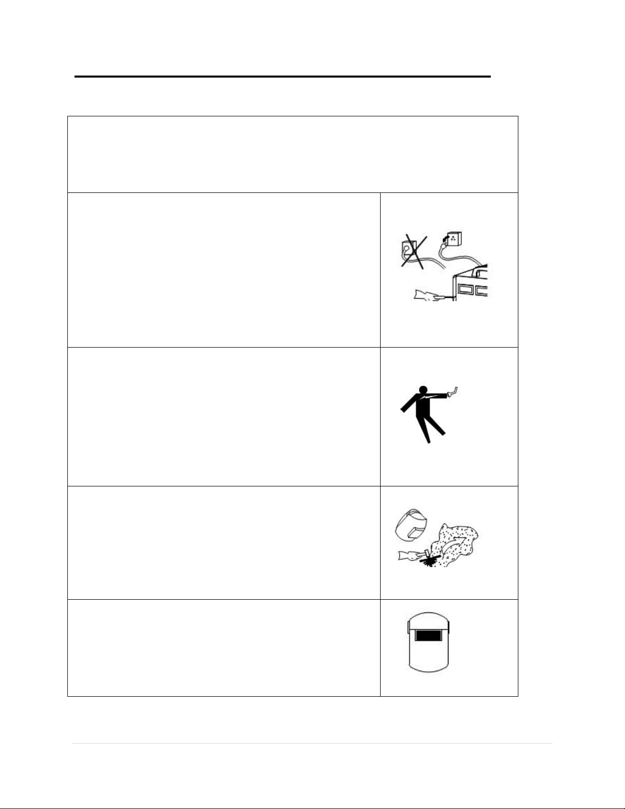
Welding and plasma cutting may be dangerous to the operator and to bystanders, if the
equipment is not operated properly. Welding or cutting must be performed in accordance with
all relevant safety regulations. Carefully read and understand this instruction manual before
installing and operating this equipment.
Changing function modes during welding may damage
equipment.
Before welding, disconnect the electrode-holder cable from the
equipment.
A circuit breaker is required to prevent electrical overload of the
equipment.
Only high quality welding tools should be used.
Electric Shock can be fatal.
Ensure that ground cable is connected in accordance with
applicable safety codes.
Never touch electrodes, wires, or circuit components with bare
hands. Wear dry welding gloves when welding.
The operator must be insulated from the work piece.
Smoke and gas can be harmful to health.
Ensure that the working area is well ventilated.
Avoid breathing smoke and gas generated during the welding
process. Cutting and welding can cause cancer because of the
smoke that comes from the welds and cuts.
Arc-light emission can be harmful to eyes and skin.
Always wear a welding helmet, anti-radiation glass, and work
clothes while welding.
Ensure that people in or near the working area are protected.
Warnings and Safety
www.longevity-inc.com
Page 6 of 37
Page 8
160/205 MIG Welder/ARC Welder
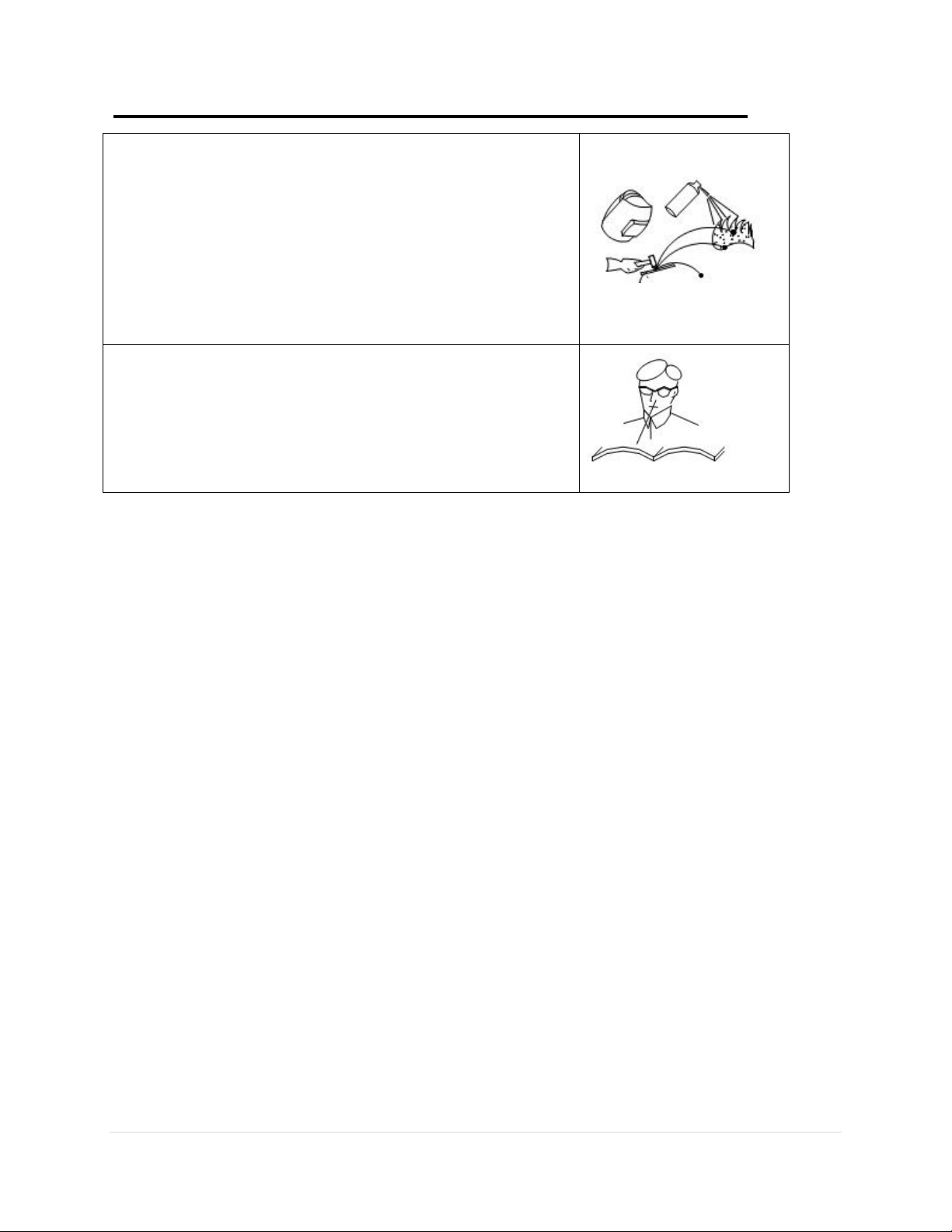
Welding splash is a fire hazard.
Keep flammable material away from the work place.
Keep a fire extinguisher nearby, and have all personnel trained in
its use.
Surface noise generated while welding or cutting can be harmful
to hearing.
In the event of a machine fault.
Refer to this instruction manual.
If the fault cannot be determined, contact your local dealer or
supplier for assistance.
www.longevity-inc.com
Page 7 of 37
Page 9

160/205 MIG Welder/ARC Welder
Safety Tips
Consider the following tips to ensure safe operation of your welding/cutting equipment:
Ensure that this welding equipment is installed in an area free of corrosive chemical gases,
flammable gases or materials, and explosive chemicals.
The area should contain little dust, and have a humidity of no more than 80%.
Operate the welding equipment in an area sheltered from direct sunlight and precipitation. Work
area temperature should be maintained at - to
If, because of an overload, the machine suddenly stops, and it is necessary to restart it, leave the
internal fan operating to lower the inside temperature.
Always wear protective clothing and a welding mask to protect your skin.
Wear safety goggles designed to darken the arc generated by your machine.
Wear suitable noise protection to protect your hearing.
Ensure that machine is grounded through the power cord or on the machine case.
Never operate the machine in bare feet or on a wet floor.
Never switch the machine off while it’s in use. Doing so will damage the internal circuitry.
Ensure that your circuit breaker is rated to handle the current requirements of your machine.
Use a UL approved receptacles and plugs with your machine. Never hard wire the machine to
main power.
Work in a well ventilated area to avoid smoke. Keep your head out of the smoke. Ensure that air
is flowing away from you to avoid inhaling smoke.
Ensure proper ventilation through the machine’s louvers. Maintain a distance of at
inches between this cutting equipment and any other objects in the work area.
Use a screen or curtain designed to keep passer byes from viewing the arc.
The arc spray and metal spray from machine use may cause nearby fires. Use caution.
If, after reviewing this manual, you have any problems in setting up or operating your machine,
contact us at [email protected].
least 12
www.longevity-inc.com
Page 8 of 37
Page 10

160/205 MIG Welder/ARC Welder
General Description:
160/205 - MIG/ARC welders are the newest models in the LONGEVITY
IGBT MIG welder line up! These machines are new and improved from our previous model
M200 MIG welder! With an improved internal wire feed system and adjustable spool gun
compatibility, The ArcMate series machines compete with top model MIG welders in the
industry! This MIG welder / Stick welder combo requires a 220V single phase power supply
which can easily be found in most house power supplies or small generators! This machine
comes with full amperage and speed adjustments for faster or slower hand speeds on thicker or
thinner material! Gas shielding will be required for this machines MIG welder giving you the
best looking weld possible! Stick welder is built in for those quick and easy jobs needed to be
done with a plug and play welder. This machine is great for hobby or industrial use. This Gas
shielded MIG welder can be equipped with a Separate hand speed controlled spool gun for
welding aluminum or other materials. This machine is competitively priced, including a free 5
Year parts and labor warranty!
Please contact LONGEVITY customer service toll free 877-566-4462 for more details on this
model or the product of your choice!
www.longevity-inc.com
Page 9 of 37
Page 11
160/205 MIG Welder/ARC Welder
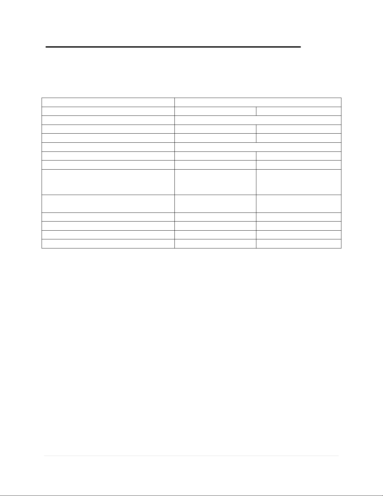
Parameter
Specifications and Ratings
Model
160
205
Input Voltage
1 phase 220v ; 50/60hz
Input Current
22amps
35amps
Rated Input Power
4.8 KVA
7.7 KVA
No Load Voltage
55~75V
Current Output Range (MIG)
30-160Amps
40-200Amps
Current Output Range (ARC)
30-135Amps
40-160Amps
Suitable Wire (Flux Cord or Solid Wire)
.025" (0.6 mm)
.030" (0.8 mm)
.035" (1.0 mm)
.025" (0.6 mm)
.030" (0.8 mm)
.035" (1.0 mm)
Duty Cycle
30% - 160A, 60% -
115A, 100% - 90A
35% - 200A, 60% -
155A, 100% - 120A
Efficiency
0.85
0.85
Power Factor
0.8
0.8
Insulation Class
F
F
Protection Class Of Shell
Fan Cooling
Fan Cooling
Specifications and Ratings
MIG shielding gas information:
Use a blended Argon/CO2 gas for best results.
100% CO2 is only used for low value welds.
A 75/25 Argon/CO2 mix is the most versatile and most common mixture.
Other mixes are available such as 85/15 Argon/CO2 to further improve weld quality.
Do not use pure Argon on mild steel.
Do not attempt to weld without a shielding gas unless a flux cored wire is used.
www.longevity-inc.com
Page 10 of 37
Page 12

160/205 MIG Welder/ARC Welder
Included Accessories:
ArcMate MIG Welder / Stick welder
MIG Torch with contact tips (10ft.)
Earth/Ground Clamp (10 ft.)
300amp Stick holder (10ft.)
Hose for argon hook up
220V Power Plug For Power Cord (110v will work on a model that specifies 110v/220v on
the back of the unit)
Pictures of Accessories: (Note: ArcMate 205 Accessories Pictured)
Superior MIG Gun Lead 400AMP Stick Holder
www.longevity-inc.com
Page 11 of 37
Page 13

160/205 MIG Welder/ARC Welder
Included Parts Continued...
Durable Ground Clamp Gas Hose for Connection to Machine
220V Power Plug for Power Cord
www.longevity-inc.com
Page 12 of 37
Page 14

160/205 MIG Welder/ARC Welder
Installation and Setup Instructions:
The item numbers referenced in the following paragraphs, refer to the numbered parts display in the
diagrams shown below. Longevity has an instructional setup installation video on our website at
www.longevity-inc.com, which we ask that you view prior installing the unit. The video shows the
complete assembly of the machine. The video is located in the Resources section of the website under
manuals and installation/set-up videos.
Connecting the electrical plug to the unit
Connecting the power plug to the unit is important. Please view the proper connection instructions below:
Wiring Introduction:
Danger: Read this manual completely before having your electrician attempt to wire up or connect your
machine to an electrical power source. Longevity units should be wired by a certified electrician to insure
your safety and a proper 220v plug match at your operating facility. 220v plugs come with 3 or 4 prongs
on them. Have the electrician check your existing receptacle.
Note: The power cord on single-phase machines has one ground wire and two hot wires when
connecting to 220vac. Connecting the plug connection to these wires is extremely important.
Improperly connected wires will void the warranty, affect personnel safety, and possibly damage your
machine and electrical power outlet.
www.longevity-inc.com
Page 13 of 37
Page 15

160/205 MIG Welder/ARC Welder
Identifying
Caution: The machine may appear to operate with an incorrectly connected ground wire, but it will not
operate properly. Selecting the correct ground wire is important for proper machine operation and
personnel safety.
Ground wires on Longevity™ machines are usually one of the following colors:
The ground wire is a dark green with a yellow stripe. The wire may also be just SOLID GREEN.
Clean the ends of the wires to more easily distinguish the colors. The best and safest way to determine
which wire is ground is to measure the resistance between the machine chassis and the selected wire,
using an ohmmeter. Another method is to check the continuity between the chassis and the wire, using a
continuity meter. If the selected wire is ground, the connection between the chassis and the wire will
cause the meter to illuminate. If, for any reason, you cannot visually detect the ground wire or do not feel
comfortable with your selection, ask an electrician for help.
Identifying
For 220vac service, both the brown and blue wire will be positive wires. As you may know, 220vac
features two hot wires. If you are wiring to 220vac, your blue and brown wires are both hot. The
green with yellow or SOLID GREEN is the ground. Remember, any hot wire can be attached to
either hot leg on the plug.
Note: Hot Wires May also be WHITE and BLACK if a GREEN WIRE is one of the three
wires. Therefore, GREEN is ALWAYS GROUND.
the Ground wire:
the hot wire:
Finished Plug:
www.longevity-inc.com
Page 14 of 37
Page 16

160/205 MIG Welder/ARC Welder
Basic Diagram Pictured Model ArcMate™ 160
(Note: All IGBT ArcMate series machines have same function adjustment knobs
and settings at different amperage ratings and positions on front panel.)
www.longevity-inc.com
Page 15 of 37
Page 17

160/205 MIG Welder/ARC Welder
Basic Diagram Pictured Model ArcMate™ 160
(Rear of Unit):
www.longevity-inc.com
Page 16 of 37
Page 18

160/205 MIG Welder/ARC Welder
Basic Diagram Pictured Model ArcMate™ 160
(Internal Wire Feed Compartment):
www.longevity-inc.com
Page 17 of 37
Page 19

160/205 MIG Welder/ARC Welder
Reversible Internal Wire Size Selector Ring:
0.8mm (.030”) Side of Wire Size Selector Ring
Side View Showing Grooves for 0.8mm and 1.0mm Wire Size
www.longevity-inc.com
Page 18 of 37
Page 20

160/205 MIG Welder/ARC Welder
1.0mm (.035”) Side of Wire Size Selector Ring
www.longevity-inc.com
Page 19 of 37
Page 21

160/205 MIG Welder/ARC Welder
Recommended Optional Accessories:
Argon Regulator for Gas Bottle!
SpeedAdjust 8M Spool Gun for Welding Aluminum or Stainless!
www.longevity-inc.com
Page 20 of 37
Page 22

160/205 MIG Welder/ARC Welder
Main Unit Knob/Button/Function:
1. On/Off Breaker or Switch: Either breaker or switch located on the back or front of the
unit will control the unit to be turned on or off.
2 Power Indicator: Shows unit is powered on. Indicator is present in some models with a
green LED bulb.
3 Warning indicator: Illuminates when the duty cycle has been exceeded or the machine
has overheated due to improper ventilation. Discontinue use until lamp goes out. Allow
the fan to continue to run. Once lamp goes out, you may resume using the unit.
4 + / – Connections: Polarity and ground selection lugs. Correct use of polarity is the key
to weld quality. Follow the electrode and wire manufacturers recommendations for
polarity. For Stick or MIG mode, ground connection will be inserted into the negative
post for straight polarity.
5 Digital Voltage Meter: Indicates voltage setting while operating machine in MIG mode.
6 Current Meter: Indicates current setting while operating machine in Stick mode.
7 MIG/Stick Selector Switch: Toggle switch for MIG or Stick setting.
8 Spool Gun Connection: LONGEVITY offers an optional 8 meter speed adjustable spool
gun for the MIG welder function of this machine. This option will allow you to weld
aluminum and stainless steel. Please contact LONGEVITY welding for more details on
this optional accessory.
9 Welding Voltage Adjustment Knob: Turning this adjustment knob clockwise increases
the welding voltage in MIG mode.
10 Arc Force Adjustment Knob: This adjustment will allow you to adjust the ARC quality
of a weld in Stick or MIG mode. Using this function while MIG welding will allow you
to control the burn back and stick out. Using this function while Stick welding will allow
you to adjust the sharpness of your ARC. Setting experimentation may be required to find
a perfect setting for an individual welder.
11 Wire Speed/ Welding Current Adjustment Knob: This adjustment has a different
function for either mode used. This will control the wire speed adjustment for rate of wire
output while MIG welding. This adjustment will also control the amperage output for
Stick welding.
12 Fuse: Fuse may need to be replaced if there is no indication on the front panel display or
if the wire speed/welding current adjustment is not working. Must replace with an
applicable fuse for use with this machine. (Contact LONGEVITY dealer for
specifications.)
13 External Ground Lug: This may be used in some circumstances where extra grounding
is necessary for local electrical code compliance. This will allow you to ground the
machine separately with a separate wire connection. (Note: machine is grounded through
power cord.)
14 Gas Inlet: This will be the inlet of your shielding gas flow to the internal solenoid of the
machine. Use gas hose provided for this connection to the machine from gas bottle. Use
proper hose clamps for sealing hose to inlet.
www.longevity-inc.com
Page 21 of 37
Page 23

160/205 MIG Welder/ARC Welder
Welding Wire Installation:
Open the wire feed compartment and locate the wire spool mount assembly shown on internal
wire feed compartment diagram on page 12. Remove the Wing nut to from the wire spool
mount assembly and remove the round collar plate. Locate the end of the wire on the spool and
mount the spool so that it runs counter clockwise into the wire feed inlet of the wire feeder
mechanism. Reinstall the collar plate and wing nut and fasten this down over the spool so that
there is no play in between the collar and spool but the spool will still spin freely. Select the
correct position for the Wire ring selector shown on page 14-15. Included ring will allow for
.030” size wire and .035” size wire to be run through the feeder mechanism. Before feeding wire
into mechanism, trim the end of the wire to be fed. Flip back the locking lever so that the wire
can be fed through the wire inlet of the mechanism. Spring tension on the locking mechanism
may need to be relieved for the locking mechanism to open. Position the wire on the proper wire
selector ring groove. Feed wire through to the motor powered side of the wire feed mechanism.
Continue to feed the wire through the powered side until it reaches the torch lead. Flip the
locking mechanism back into the closed locked position. Tighten the locking mechanism so that
there is sufficient pressure applied to feed the wire into the gun. Do not over tighten the locking
mechanism. Readjustment of the locking mechanism may be required after wire is fed through
the torch. Do not attempt to weld with the compartment door open.
www.longevity-inc.com
Page 22 of 37
Page 24

160/205 MIG Welder/ARC Welder
Setting Up Argon Regulator:
The argon regulator pictured below is a standard size regulator for most argon tank setups.
Setting it up to your argon bottle is easy. Simply screw in the valve fitting securely to the gas
bottle. Secure your hose to the outlet of the regulator using a proper hose clamp. Set the pressure
regulator adjustment between 15-25 cubic feet per hour depending on welding conditions. Use
higher flow when extending the welding wire to reach into corners or gaps. We recommend
about 18 CFM for normal operating conditions.
www.longevity-inc.com
Page 23 of 37
Page 25

160/205 MIG Welder/ARC Welder
MIG Welding Process
Gas metal arc welding (GMAW), sometimes referred to by its subtypes metal inert gas (MIG)
welding or metal active gas (MAG) welding, is a semi-automatic or automatic arc welding
process in which a continuous and consumable wire electrode and a shielding gas are fed through
a welding gun. A constant voltage, direct current power source is most commonly used with
GMAW, but constant current systems, as well as alternating current, can be used. There are four
primary methods of metal transfer in GMAW, called globular, short-circuiting, spray, and
pulsed-spray, each of which has distinct properties and corresponding advantages and
limitations.
Originally developed for welding aluminum and other non-ferrous materials in the 1940s,
GMAW was soon applied to steels because it allowed for lower welding time compared to other
welding processes. The cost of inert gas limited its use in steels until several years later, when
the use of semi-inert gases such as carbon dioxide became common. Further developments
during the 1950s and 1960s gave the process more versatility and as a result, it became a highly
used industrial process. Today, GMAW is the most common industrial welding process,
preferred for its versatility, speed and the relative ease of adapting the process to robotic
automation. The automobile industry in particular uses GMAW welding almost exclusively.
Unlike welding processes that do not employ a shielding gas, such as shielded metal arc welding,
it is rarely used outdoors or in other areas of air volatility. A related process, flux cored arc
welding, often does not utilize a shielding gas, instead employing a hollow electrode wire that is
filled with flux on the inside.
www.longevity-inc.com
Page 24 of 37
Page 26

160/205 MIG Welder/ARC Welder
Welding gun and wire feed unit
GMAW torch nozzle cutaway image: (1) Torch handle (2) Molded phenolic dielectric (shown in white)
and threaded metal nut insert (yellow) (3) Shielding gas diffuser (4) Contact tip (5) Nozzle output face
A GMAW wire feed unit
The typical GMAW welding gun has a number of key parts—a control switch, a contact tip, a
power cable, a gas nozzle, an electrode conduit and liner, and a gas hose. The control switch, or
trigger, when pressed by the operator, initiates the wire feed, electric power, and the shielding
gas flow, causing an electric arc to be struck. The contact tip, normally made of copper and
sometimes chemically treated to reduce spatter, is connected to the welding power source
through the power cable and transmits the electrical energy to the electrode while directing it to
the weld area. It must be firmly secured and properly sized, since it must allow the passage of the
electrode while maintaining an electrical contact. Before arriving at the contact tip, the wire is
protected and guided by the electrode conduit and liner, which help prevent buckling and
maintain an uninterrupted wire feed. The gas nozzle is used to evenly direct the shielding gas
into the welding zone—if the flow is inconsistent, it may not provide adequate protection of the
weld area. Larger nozzles provide greater shielding gas flow, which is useful for high current
welding operations, in which the size of the molten weld pool is increased. The gas is supplied to
the nozzle through a gas hose, which is connected to the tanks of shielding gas. Sometimes, a
water hose is also built into the welding gun, cooling the gun in high heat operations.
www.longevity-inc.com
Page 25 of 37
Page 27

160/205 MIG Welder/ARC Welder
The wire feed unit supplies the electrode to the work, driving it through the conduit and on to the
contact tip. Most models provide the wire at a constant feed rate, but more advanced machines
can vary the feed rate in response to the arc length and voltage. Some wire feeders can reach feed
rates as high as 30.5 m/min (1200 in/min), but feed rates for semiautomatic GMAW typically
range from 2 to 10 m/min (75–400 in/min).
Tool Style
The top electrode holder is a semiautomatic air-cooled holder; compressed air is circulated
through it to maintain moderate temperatures. It is used with lower current levels for welding
lap- or butt joints. The second most common type of electrode holder is a semiautomatic watercooled; the only difference being that water takes the place of air. It uses higher current levels for
welding T- or corner joints. The third typical holder type is an automatic electrode holder that is
water cooled; this holder is used typically with automated equipment.
Power supply
Most applications of gas metal arc welding use a constant voltage power supply. As a result, any
change in arc length (which is directly related to voltage) results in a large change in heat input
and current. A shorter arc length will cause a much greater heat input, which will make the wire
electrode melt more quickly and thereby restore the original arc length. This helps operators keep
the arc length consistent even when manually welding with hand-held welding guns. To achieve
a similar effect, sometimes a constant current power source is used in combination with an arc
voltage-controlled wire feed unit. In this case, a change in arc length makes the wire feed rate
adjust in order to maintain a relatively constant arc length. In rare circumstances, a constant
current power source and a constant wire feed rate unit might be coupled, especially for the
welding of metals with high thermal conductivities, such as aluminum. This grants the operator
additional control over the heat input into the weld, but requires significant skill to perform
successfully.
Alternating current is rarely used with GMAW; instead, direct current is employed and the
electrode is generally positively charged. Since the anode tends to have a greater heat
concentration, this will result in faster melting of the feed wire, which increases weld penetration
and welding speed. The polarity can be reversed only when special emissive-coated electrode
wires are used, but since these are not popular, a negatively charged electrode is rarely
employed.
Electrode
Electrode selection is based primarily on the composition of the metal being welded, the process
variation being used, joint design and the material surface conditions. Electrode selection greatly
influences the mechanical properties of the weld and is a key factor of weld quality. In general
the finished weld metal should have mechanical properties similar to those of the base material
with no defects such as discontinuities, entrained contaminants or porosity within the weld. To
achieve these goals a wide variety of electrodes exist. All commercially available electrodes
Page 26 of 37
www.longevity-inc.com
Page 28

160/205 MIG Welder/ARC Welder
contain deoxidizing metals such as silicon, manganese, titanium and aluminum in small
percentages to help prevent oxygen porosity. Some contain denitriding metals such as titanium
and zirconium to avoid nitrogen porosity. Depending on the process variation and base material
being welded the diameters of the electrodes used in GMAW typically range from 0.7 to 2.4 mm
(0.028–0.095 in) but can be as large as 4 mm (0.16 in). The smallest electrodes, generally up to
1.14 mm (0.045 in) are associated with the short-circuiting metal transfer process, while the most
common spray-transfer process mode electrodes are usually at least 0.9 mm (0.035 in).
GMAW circuit diagram: (1) Welding torch (2) Work piece (3) Power source (4) Wire feed unit (5)
Electrode source (6) Shielding gas supply
Shielding gas
Main article: Shielding gas
Shielding gases are necessary for gas metal arc welding to protect the welding area from
atmospheric gases such as nitrogen and oxygen, which can cause fusion defects, porosity, and
weld metal embrittlement if they come in contact with the electrode, the arc, or the welding
metal. This problem is common to all arc welding processes; for example, in the older ShieldedMetal Arc Welding process (SMAW), the electrode is coated with a solid flux which evolves a
protective cloud of carbon dioxide when melted by the arc. In GMAW, however, the electrode
wire does not have a flux coating, and a separate shielding gas is employed to protect the weld.
This eliminates slag, the hard residue from the flux that builds up after welding must be chipped
off to reveal the completed weld.
The choice of a shielding gas depends on several factors, most importantly the type of material
being welded and the process variation being used. Pure inert gases such as argon and helium are
only used for nonferrous welding; with steel they do not provide adequate weld penetration
(argon) or cause an erratic arc and encourage spatter (with helium). Pure carbon dioxide, on the
other hand, allows for deep penetration welds but encourages oxide formation, which adversely
affect the mechanical properties of the weld. Its low cost makes it an attractive choice, but
because of the reactivity of the arc plasma, spatter is unavoidable and welding thin materials is
difficult. As a result, argon and carbon dioxide are frequently mixed in a 75%/25% to 90%/10%
mixture. Generally, in short circuit GMAW, higher carbon dioxide content increases the weld
heat and energy when all other weld parameters (volts, current, electrode type and diameter) are
www.longevity-inc.com
Page 27 of 37
Page 29

160/205 MIG Welder/ARC Welder
held the same. As the carbon dioxide content increases over 20%, spray transfer GMAW
becomes increasingly problematic, especially with smaller electrode diameters.
Argon is also commonly mixed with other gases, oxygen, helium, hydrogen, and nitrogen. The
addition of up to 5% oxygen (like the higher concentrations of carbon dioxide mentioned above)
can be helpful in welding stainless steel, however, in most applications carbon dioxide is
preferred. Increased oxygen makes the shielding gas oxidize the electrode, which can lead to
porosity in the deposit if the electrode does not contain sufficient deoxidizers. Excessive oxygen,
especially when used in application for which it is not prescribed, can lead to brittleness in the
heat affected zone. Argon-helium mixtures are extremely inert, and can be used on nonferrous
materials. A helium concentration of 50%–75% raises the required voltage and increases the heat
in the arc, due to helium's higher ionization temperature. Hydrogen is sometimes added to argon
in small concentrations (up to about 5%) for welding nickel and thick stainless steel material. In
higher concentrations (up to 25% hydrogen), it may be used for welding conductive materials
such as copper. However, it should not be used on steel, aluminum or magnesium because it can
cause porosity and hydrogen embrittlement. Additionally, nitrogen is sometimes added to argon
to a concentration of 25%–50% for welding copper, but the use of nitrogen, especially in North
America, is limited.
Shielding gas mixtures of three or more gases are also available. Mixtures of argon, carbon
dioxide and oxygen are marketed for welding steels. Other mixtures add a small amount of
helium to argon-oxygen combinations, these mixtures are claimed to allow higher arc voltages
and welding speed. Helium is also sometimes used as the base gas, with small amounts of argon
and carbon dioxide added. However, because it is less dense than air, helium is less effective in
shielding the weld than argon– which is denser than air. It also can lead to arc stability and
penetration issues and increased spatter, due to the much more energetic arc plasma. Helium is
also more expensive than other shielding gases. Other specialized and often proprietary gas
mixtures claim even greater benefits for specific applications.
The desirable rate of gas flow depends primarily on weld geometry, speed, current, the type of
gas, and the metal transfer mode being utilized. Welding flat surfaces requires higher flow than
welding grooved materials, since the gas is dispersed more quickly. Faster welding speeds, in
general, mean that more gas needs to be supplied to provide adequate coverage. Additionally,
higher current requires greater flow, and generally, more helium is required to provide adequate
coverage than argon. Perhaps most importantly, the four primary variations of GMAW have
differing shielding gas flow requirements—for the small weld pools of the short circuiting and
pulsed spray modes, about 10 L/min (20 ft³/h) is generally suitable, while for globular transfer,
around 15 L/min (30 ft³/h) is preferred. The spray transfer variation normally requires more
because of its higher heat input and thus larger weld pool; along the lines of 20–25 L/min (40–
50 ft³/h).
www.longevity-inc.com
Page 28 of 37
Page 30

160/205 MIG Welder/ARC Welder
Operation
GMAW weld area: (1) Direction of travel (2) Contact tube (3) Electrode (4) Shielding gas (5) Molten
weld metal (6) Solidified weld metal (7) Work piece
For most of its applications gas metal arc welding is a fairly simple welding process to learn
requiring no more than a week or two to master basic welding technique. Even when welding is
performed by well-trained operators weld quality can fluctuate since it depends on a number of
external factors. All GMAW is dangerous, though perhaps less so than some other welding
methods, such as shielded metal arc welding.
Technique
The basic technique for GMAW is quite simple, since the electrode is fed automatically through
the torch. By contrast, in gas tungsten arc welding, the welder must handle a welding torch in
one hand and a separate filler wire in the other, and in shielded metal arc welding, the operator
must frequently chip off slag and change welding electrodes. GMAW requires only that the
operator guide the welding gun with proper position and orientation along the area being welded.
Keeping a consistent contact tip-to-work distance (the stick out distance) is important, because a
long stickout distance can cause the electrode to overheat and will also waste shielding gas.
Stickout distance varies for different GMAW weld processes and applications. For short-circuit
transfer, the stickout is generally 1/4 inch to 1/2 inch, for spray transfer the stickout is generally
1/2 inch. The position of the end of the contact tip to the gas nozzle is related to the stickout
distance and also varies with transfer type and application. The orientation of the gun is also
important—it should be held so as to bisect the angle between the work piece; that is, at 45
degrees for a fillet weld and 90 degrees for welding a flat surface. The travel angle, or lead angle,
is the angle of the torch with respect to the direction of travel, and it should generally remain
approximately vertical. However, the desirable angle changes somewhat depending on the type
www.longevity-inc.com
Page 29 of 37
Page 31

160/205 MIG Welder/ARC Welder
of shielding gas used—with pure inert gas’s, the bottom of the torch is often slightly in front of
the upper section, while the opposite is true when the welding atmosphere is carbon dioxide.
Quality
Two of the most prevalent quality problems in GMAW are dross and porosity. If not controlled,
they can lead to weaker, less ductile welds. Dross is an especially common problem in aluminum
GMAW welds, normally coming from particles of aluminum oxide or aluminum nitride present
in the electrode or base materials. Electrode and work piece must be brushed with a wire brush or
chemically treated to remove oxides on the surface. Any oxygen in contact with the weld pool,
whether from the atmosphere or the shielding gas, causes dross as well. As a result, sufficient
flow of inert shielding gases is necessary, and welding in volatile air should be avoided.
In GMAW the primary cause of porosity is gas entrapment in the weld pool, which occurs when
the metal solidifies before the gas escapes. The gas can come from impurities in the shielding gas
or on the work piece, as well as from an excessively long or violent arc. Generally, the amount of
gas entrapped is directly related to the cooling rate of the weld pool. Because of its higher
thermal conductivity, aluminum welds are especially susceptible to greater cooling rates and thus
additional porosity. To reduce it, the work piece and electrode should be clean, the welding
speed diminished and the current set high enough to provide sufficient heat input and stable
metal transfer but low enough that the arc remains steady. Preheating can also help reduce the
cooling rate in some cases by reducing the temperature gradient between the weld area and the
base material.
www.longevity-inc.com
Page 30 of 37
Page 32

160/205 MIG Welder/ARC Welder
STICK/ARC Welding
(Also known as MMA-Manual Metal Arc or Shielded Metal Arc Welding-SMAW)
Connect the Stick torch to the - terminal and Torch Control receptacles.
Connect the ground clamp to the + terminal and clamp the metal to be welded. Reverse the torch and
ground connections for DCEP (Direct Current Electrode Positive).
DC Stick - Select Stick, DC, desired amps using Base cur knob, Pulse Mode off.
1. Insert electrode into electrode holder. Position the electrode for the most comfortable position so that
the electrode can be held directly over the work piece with a slight angle.
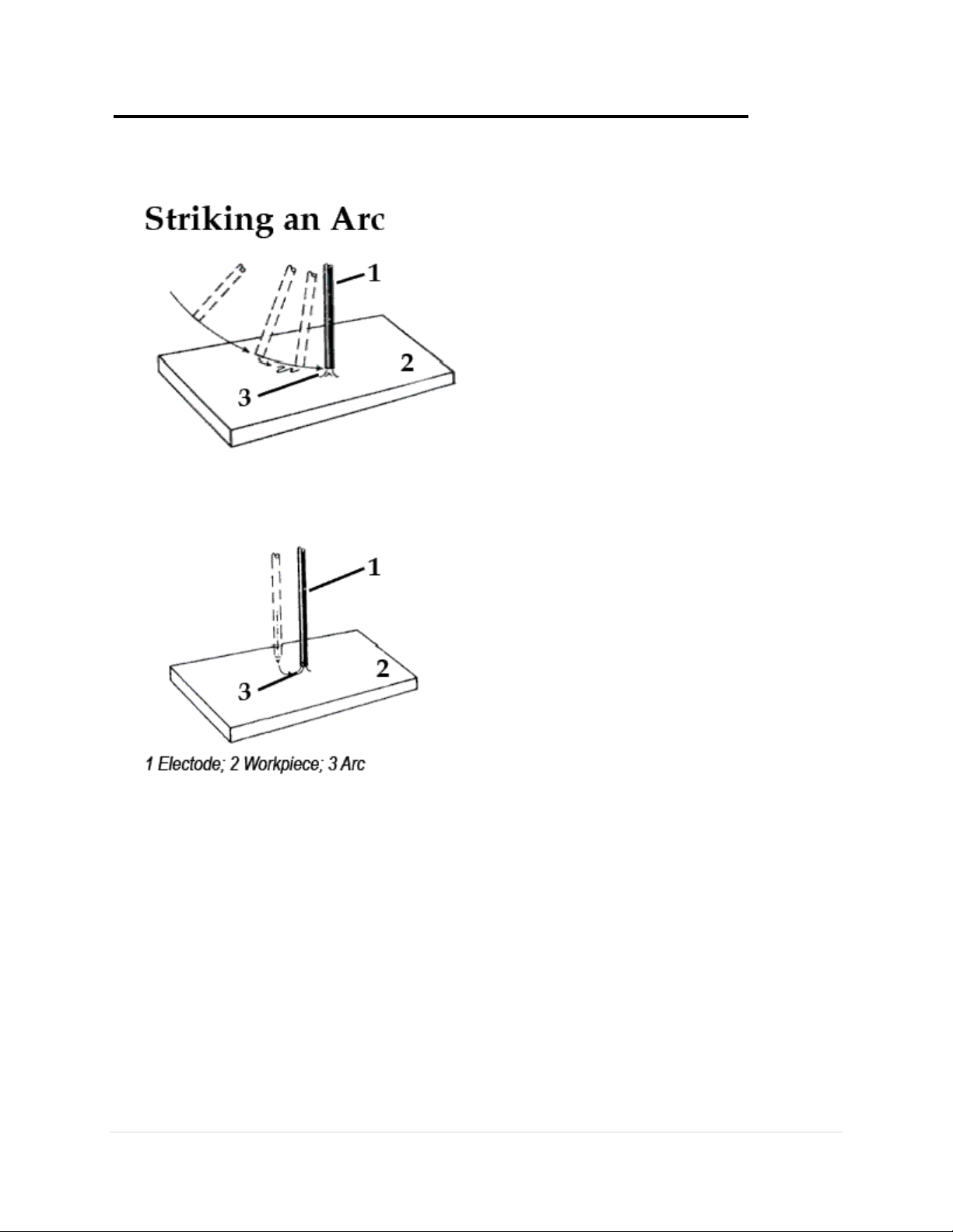
2. Set Amperage to the recommended amperage by the electrode manufacturer. Strike an arc by swiping it
briskly across the work piece in the same manner as one would strike a match. Alternatively, you may
strike an arc with firm tapping motion against the work piece. Either method is acceptable. An arc should
initiate. Continue to keep the arc going by holding the electrode off the work piece no more than the
electrode width.
3. Continue the arc by feeding the electrode into the weld puddle while moving the electrode forward.
This will take some coordination, but will be fairly easy to do after practice. Do not allow the arc to
become too long, because air and slag can become entrapped in the metal. The sound of a proper arc will
be similar to a gentle frying sound. A long arc will emit a humming sound. An arc that is too short may be
extinguished and the electrode may stick to the work piece. If the electrode sticks, immediately release
the electrode from the electrode holder and break the electrode loose by hand. If the flux breaks off,
simply trim off the excess rod until flux and bare metal meet. A welding rod must have flux to shield the
weld from the atmosphere or the weld will fail.
4. Use the Current control to change arc qualities. Adjust the amperage according to the
recommendations of the electrode (welding rod) manufacturer for the type and size of the electrode used.
Experimentation will be required to find the optimal setting desired. It is an excellent tool for out of
position welding.
5. Electrode selection. Electrodes are usually given performance and characteristic ratings using a system
of letters and numbers determined by the American Welding Society (AWS). The rating system includes
the minimum tensile strength of the finished weld, the weld position (flat, vertical, horizontal, or overhead
www.longevity-inc.com
Page 31 of 37
Page 33

160/205 MIG Welder/ARC Welder
or a combination of two or more positions) and the flux type. Additional information may be given. Each
manufacturer has their individual name and terminology as well. As there is no general recommendation
that can be made about a particular electrode selection, except for practice welds, a electrode designated
by the AWS as E 6011, E 6013, E 7014, or E 7018 may be used, each having its own distinct features and
purpose. These are among the most common electrodes used in the industry and are not difficult to find. E
6011 electrodes are not as smooth running as some of the other electrodes, but offer the advantage of
being able to weld on rusty metal and contaminated surfaces. It is widely used and requires very little skill
to begin using. This is not a particular endorsement of an E6011, rather a simple example of what may be
used in developing proficient technique. It is recommended that a variety of electrodes be used and
practiced with. Consultation with an experienced local welding supplier will help greatly in determining
what welding electrode is the best for your given situation. Many times, samples or small packages of
electrodes are available at relatively low cost.
Stick Electrode Chart Example: E 60 1 3
Strength
60--60,000 psi,
70--70,000 psi
Weld Position
1--All positions: Flat, Vertical, Horizontal, & Overhead
2--Flat Position or Horizontal Fillets Only
3--Flat Position Only
Weld Characteristics
0--Non-low hydrogen, DC Reverse polarity
1--Non-low hydrogen, AC or DC Reverse polarity
2--Non-low hydrogen, AC or DC Straight polarity
3--Non-low hydrogen, AC or DC Either polarity
4--Non-low hydrogen, iron powder coating, AC or DC Reverse polarity
5--Low-hydrogen, DC Reverse polarity
6--Low-hydrogen, AC or DC Reverse polarity
7--Non-low hydrogen, iron powder coating, AC or DC Reverse polarity
8--Low hydrogen, iron powder coating, AC or DC Reverse polarity
Polarity Definition
electrode negative =straight polarity (typical stock machine setup)
electrode positive = reverse polarity
Be sure to observe the electrode manufacturer recommendations regarding polarity. If the weld appears
lumpy, porous or otherwise malformed, change the polarity of the ground cable and the electrode holder
cable. Many electrodes run with in reverse polarity, (DCEP) setting. A few run with a straight polarity
(DCEN). Some will run either way. For reverse polarity (DCEP) stick welding, swap the electrode holder and
www.longevity-inc.com
Page 32 of 37
Page 34

160/205 MIG Welder/ARC Welder
ground cable connections.
Proper weld identification: Overlap and undercutting are two main causes of weld failure. Proper washing
of the weld bead into the sides or “toes” of the weld is important. Keep the welding electrode or the TIG
tungsten and welding arc within the weld joint to prevent overlap. Pausing on the sides of the welds to
wait for the sides to fill reduces the chance of undercutting, even if the current is a little too high. If it is
possible, with any practice weld, cut the joint down the middle, lengthwise, or place the weld in a vice and
use a hammer to bend the metal over the weld area until it is either broken or bent 90 degrees. This
destructive testing method will help you improve your skill by revealing faults and flaws in your welds.
www.longevity-inc.com
Page 33 of 37
Page 35

160/205 MIG Welder/ARC Welder
Stick (SMAW) Electrode Welding
Stick, the most basic of welding processes, offers the easiest option for joining steel and other metals.
Although it produces the least pretties or cleanest welds, ARC/STICK welding gets the job done! Stick welding
power sources deliver inexpensive options for welding versatility, portability and reliability. Stick joins metals
when an arc is struck between the electrode and the work piece, creating a weld pool and depositing a
consumable metal electrode into the joint. The electrode's protective coating also acts as a shielding gas,
protecting the weld and ensuring its purity and strength. Best for windy conditions and adverse environments.
If you’re not familiar with Stick (SMAW) welding basics, the following information can make choosing an
electrode easier.
AWS
Class
Position
Polarity
Usage
E6010
All
DCEP
A great choice for welding on dirty, rusty, greasy or painted steel
- especially in vertical or overhead applications.
E6011
All
AC,DCEP
All-purpose stick electrode; used for carbon and galvanized steel;
60,000 PSI tensile strength; deep penetration and ideal for
welding light to medium amounts of dirty, rusty or painted
materials.
E6013
All
AC,DCEN,DCEP
Light to medium penetrating all-purpose stick electrode; for use
on carbon steel; 60,000 PSI tensile strength; good for general all-
purpose applications and joints with poor fit-up.
E7014
All
AC,DCEN,DCEP
For higher-deposition requirements; 70,000 PSI tensile strength;
ideal for applications requiring light penetration and faster travel
speeds.
E7018
All
DCEP
Low-hydrogen electrode; for low, medium and high-carbon
steels; 70,000 PSI tensile strength; ideal for out-of-position
welding and tacking; not recommended for low-voltage AC
Welders.
E7018AC
All
AC,DCEP
Low-hydrogen electrode; for low, medium and high-carbon
steels; 70,000 PSI tensile strength; ideal for out-of-position
welding and tacking; specially formulated to operate with small
208/230 volt AC welders.
www.longevity-inc.com
Page 34 of 37
Page 36
160/205 MIG Welder/ARC Welder
Page 35 of 37
www.longevity-inc.com
Page 37
160/205 MIG Welder/ARC Welder
Helpful Hints
Use a drag technique for most applications.
Take precautions with flying materials when
chipping slag.
Keep electrodes clean and dry - follow
manufacturer instructions.
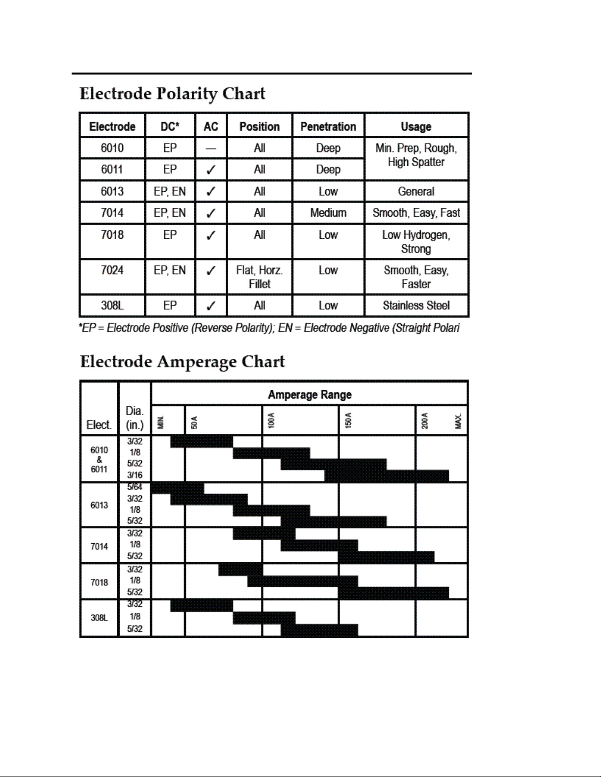
Common steel electrodes (refer to chart
above).
Penetration: DCEN- Less penetration; AC -
Medium (can be more spatter also); DCEP - Most
penetration
Catalog and Capabilities
LONGEVITY has what you need for stick welding,
from welders to welding supplies and protective
clothing. Stick welders come in two basic
classifications; 115V stick welders and 230/460V stick
welders. Stick Electrodes or welding rod for stick
welding are available in stainless steel, carbon steel,
low alloy steel, maintenance alloy, hard facing, nickel
alloy, and magnesium
www.longevity-inc.com
Page 36 of 37
Page 38

160/205 MIG Welder/ARC Welder
Routine Maintenance
The life of your machine and the quality of the work performed using your machine, will be enhanced by
practicing periodic routine maintenance.
At regular intervals, clear dust that may accumulate in the machine using clean and dry compressed air.
If the working condition has heavy smoke and pollution, the welding machine should be cleaned once a
month.
Keep the machine exterior clean with mild soap and water.
Do not walk on or store items on the cables or cords.
Do not jar, drop, or stack items on top of the machine.
Always connect the machine to a proper grounded electrical outlet.
Always check the torch consumables before and after use and ensure that they are clear of obstructions,
and that no parts are damaged.
Replace any worn or damaged consumables before using machine.
For periods of prolonged non-use, remove cables and store them in their original boxes in a cool dry
place, free of bug infestation.
www.longevity-inc.com
Page 37 of 37
Page 39

160/205 MIG Welder/ARC Welder
LONGEVITY® Global, Inc. thanks you for your purchase and the opportunity to be able to serve you. If,
after reviewing this manual, you have any problems in setting up or operating your machine, contact us
at [email protected].
LONGEVITY® Global, Inc.
Toll-Free 1-877-LONG-INC / 1-877-566-4462
Website: www.longevity-inc.com
Sales: [email protected]
Customer Service: [email protected]
Dealers: [email protected]
Please join our welding forums to share welding tips and tricks, to receive useful information from
customers who also use our products, and to be a part of the LONGEVITY® welding community at
www.freeweldingforum.com
For the coolest LONGEVITY sponsored race teams plus a complete racing forum that covers everything
from Drag Racing to RC Car Racing, please check out www.longevity-racing.com!
Enjoy your new welding machine from LONGEVITY! Thanks again!
www.longevity-inc.com
Page 38 of 37
 Loading...