

Page 1
BaodingLongerPrecisionPumpCo.,Ltd.
Building A, Chuangye Center Baoding National
High-Tech Industrial Development Zone
Baoding, Hebei, China 071051
TEL: 86-312-3110087
FAX: 86-312-3168553
E-mail: [email protected]
Http //www.longerpump.com:
,
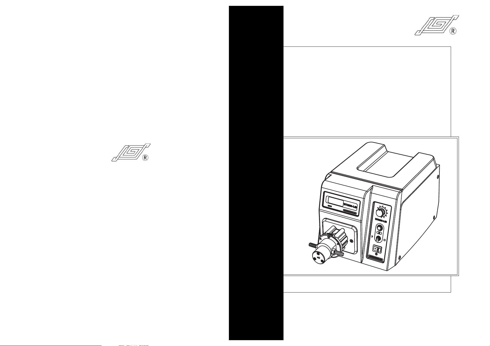
Micro Gear Pump Drive
WT3000-1FB Gear Pump Drive
WT3000-1 B
F
Operating Manual
Baoding Longer Precision Pump Co.,Ltd.
Page 2
Micro Gear Pump Drive Operating Manual
Important Information:
Please read operating manual carefully before operation.
Warning:
To prevent damage to pump, do not run the pump dry.
If the power line or the plug are worn or damaged please pull out
the plug (Hold the plug not the power line when pulling out).
Please shut down the power supply and pull out the plug when you
think the pump needs to be maintained or repaired.
Shut down the power supply of the pump when connecting to
external control equipment.
The International Protection rating of this pump is IP31. Do not let
liquid enter this pump drive.
Warranty:
The warranty period of this product is one year. If repair or
adjustment is necessary within the warranty period, the problem
will be corrected at no charge if it is not due to misuse or abuse on
your part, as determined by the manufacturer. Repair costs out
side the warranty period, or those resulting from product misuse or
abuse, may be invoiced to you.
Contact Longer Company or Longer’s dealers before returning
pump to repair.
Adopt original carton or reliable package when returning pump to
repair.
Write a note on detailed description of failure phenomena and
contact information and put this note along with pump before
returning pump to repair.
Table of Contents
Instruction
Basic Operation
Running Interface
Menu Navigation Diagram
Pump Head Operation
Pump Head Installation
Pump Head Flow Rates
Pump Head Setting
Flow Mode Operation
Enter Flow Mode
Flow Control
Flow Calibration
Flow Mode Operation Procedure
Dispensing Mode Operation
Enter Dispensing Mode
Dispensing Volume
Copy No.
Flow Rate Setting
Pause Time
Dispensing Calibration
Dispensing Mode Operation Procedure
External Control
External Enable Setting
Analog Signal Control
Footswitch Control
Communication Control Mode
External Control Output
Maintenance
Technical Specifications
1
2
3
4
5
5
5
5
6
6
6
6
7
7
7
7
8
8
8
9
9
10
10
10
11
12
13
13
13
Page 3
Micro Gear Pump Drive Operating Manual
Micro Gear Pump Drive Operating Manual
Instruction
Acceptable pump heads for WT3000-1FB are MG204, MG209 and
MG213. The pump delivers flow rates from 83 to 2750 mL/min and
dispensing volume is from 0.1 mL to 999 L. Combining 128 32 LCD
display with membrane keypad and rotary coded switch makes the
operation easy and prompt. The speed can be adjusted manually or
automatically through external control interface.
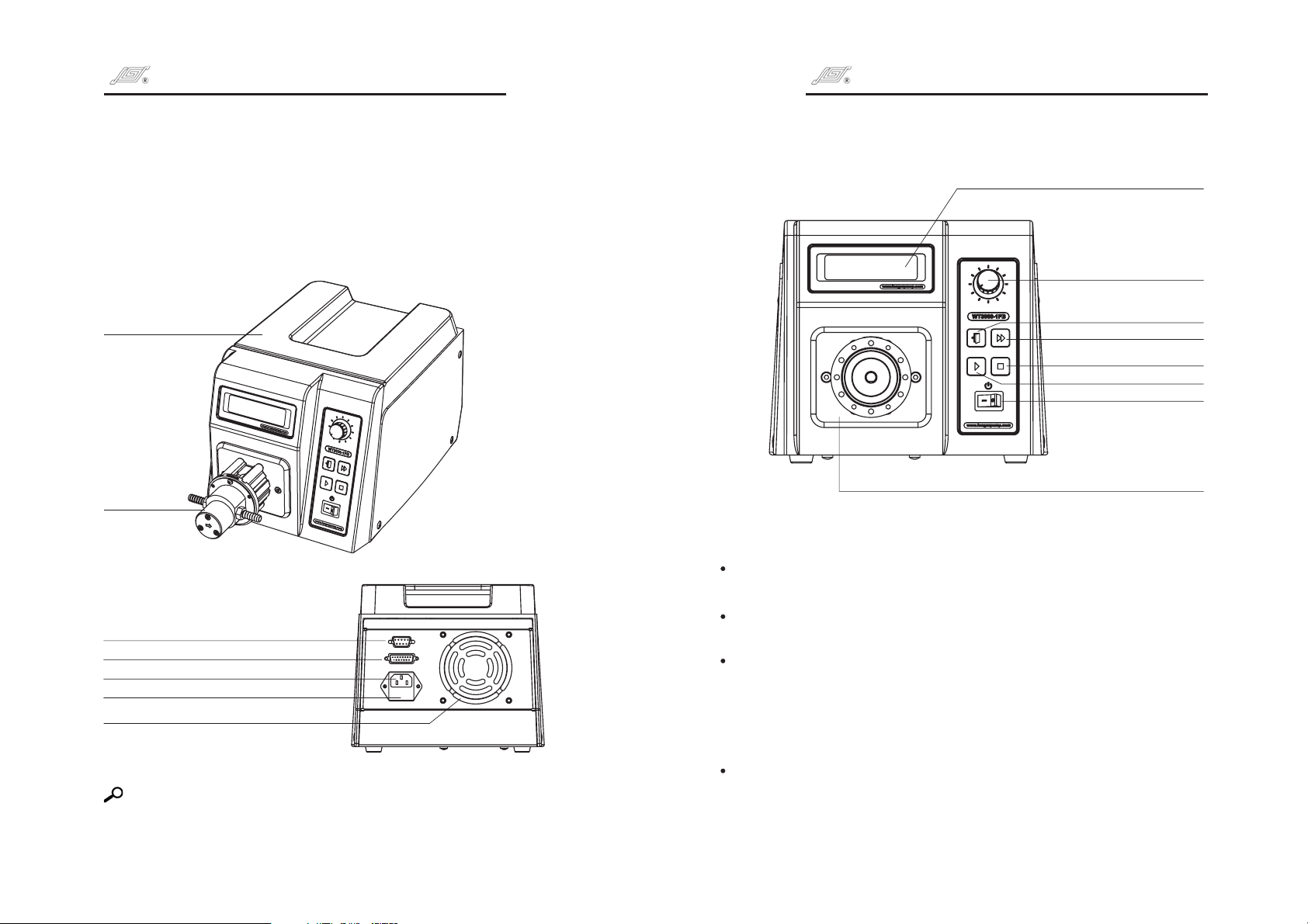
Drive
Pump Head
External Control Output Interface
External Control Input Interface
Power Socket
Fuse Holder
Fan
Reference:
Refer to page 10 to know the functions of External Control.
1 2
Basic Operation
LCD Display
Exit Key
Prime Key
Stop Key
Run Key
Power Switch
Pump Head Connecting Board
Run Key
In stop state, press , the pump starts to run.
Stop Key
In non-prime state, press , the pump stops.
Prime Key
When the pump is in flow rates mode state (the pump runs or stops) or in
dispensing mode (the pump stops), press the to enter prime
state when the pump runs at full speed for empting, filling and rinsing
operation; Press the again to return to common state. In prime
state, other keys are invalid.
Exit Key
Function 1: Cancel current operation and return to previous menu.
Function 2: In dispensing mode, press to switch different
dispensing parameters display.
Run Key
Stop Key
Prime Key
Prime Key
Exit Key
Knob
Page 4
Micro Gear Pump Drive Operating Manual
Micro Gear Pump Drive Operating Manual
Knob
Function 1: Turn the to adjust the flow rates in flow rates display state.
Function 2: Turn the to select the menu and set the parameters, press
for confirmation in menus selection state.
Knob
Power Switch
Turn on or off the pump.
Knob
Knob
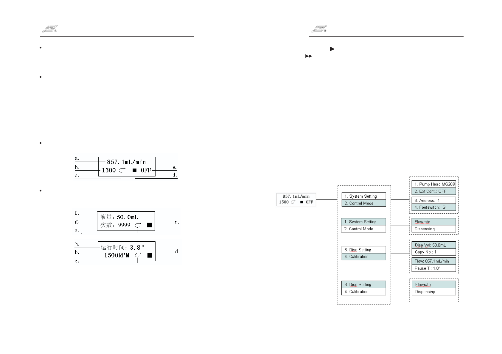
Running Interface
Turn on the pump, the pump is initialized first and select the language.
Chinese and English are available. Turn the Knob to select the
language. Then the pump displays the running interface.
Flow rates display
Dispensing display: Dispensing parameters are displayed in two
interfaces, Press Exit Key to switch these two interfaces.
d. Running status: means the pump runs; means the pump
【】
stops; means the pump is in prime state.
e. Control mode: INT means the pump is controlled internally; V means the
pump is controlled by external analog voltage signal; mA means the
pump is controlled by external analog current signal; Hz means the pump
is controlled by external 0 10 kHz pulse signal. Off means shutting off the
external control function by setting menu;
f. Dispensing volume: Display dispensing volume in dispensing mode.
g. Copy number: Display copy number under dispensing mode.
h. Dispensing time: Display the dispensing time. When the dispensing
procedure starts, the dispensing time will be counted down. Adjust the
flow rates or dispensing volume to change the dispensing time in
dispensing parameters setting interface.
【】 【】
Menu Navigation Diagram
a. Current flow rates: Display current flow rates. Turn the Knob to
increase or decrease the flow rates.
b. Current speed: Display current speed. The speed will change when
adjusting the flow rates.
c. Running direction: Indicate the direction of the pump. The running
direction of the pump can't be changed.
3 4
Page 5
Micro Gear Pump Drive Operating ManualMicro Gear Pump Drive Operating Manual
Pump Head Operation
Pump Head Installation:
The pump head is mounted on drive before the pump leaves the factory.
Follow below procedure for changing another pump head.
1.Loose the three M3 screws which connect the pump head and the pump
head bracket. Dismantle the pump head slightly.
2.Put the new pump head in the old pump head location. Pay attention to
the inlet and outlet locations of the pump head. Use three M3 screws to
connect the pump head and the pump head bracket.
Turn off the power supply before changing the pump head.
Pump Heads and Flow rates
MG
Part Number
MS()Strong Magnet
05015010011
05015010012
05015010013
Flow Rates(mL/min)
0 00(rpm)30 30~
85.7~857.1
171.4~1714.3
257.1~2571.4
Acceptable
Pump Heads
MS(MG)204
MS(MG)209
MS(MG)213
05015010001
05015010002
05015010003
Pump Head Setting
Flow Mode Operation
Enter Flow Mode
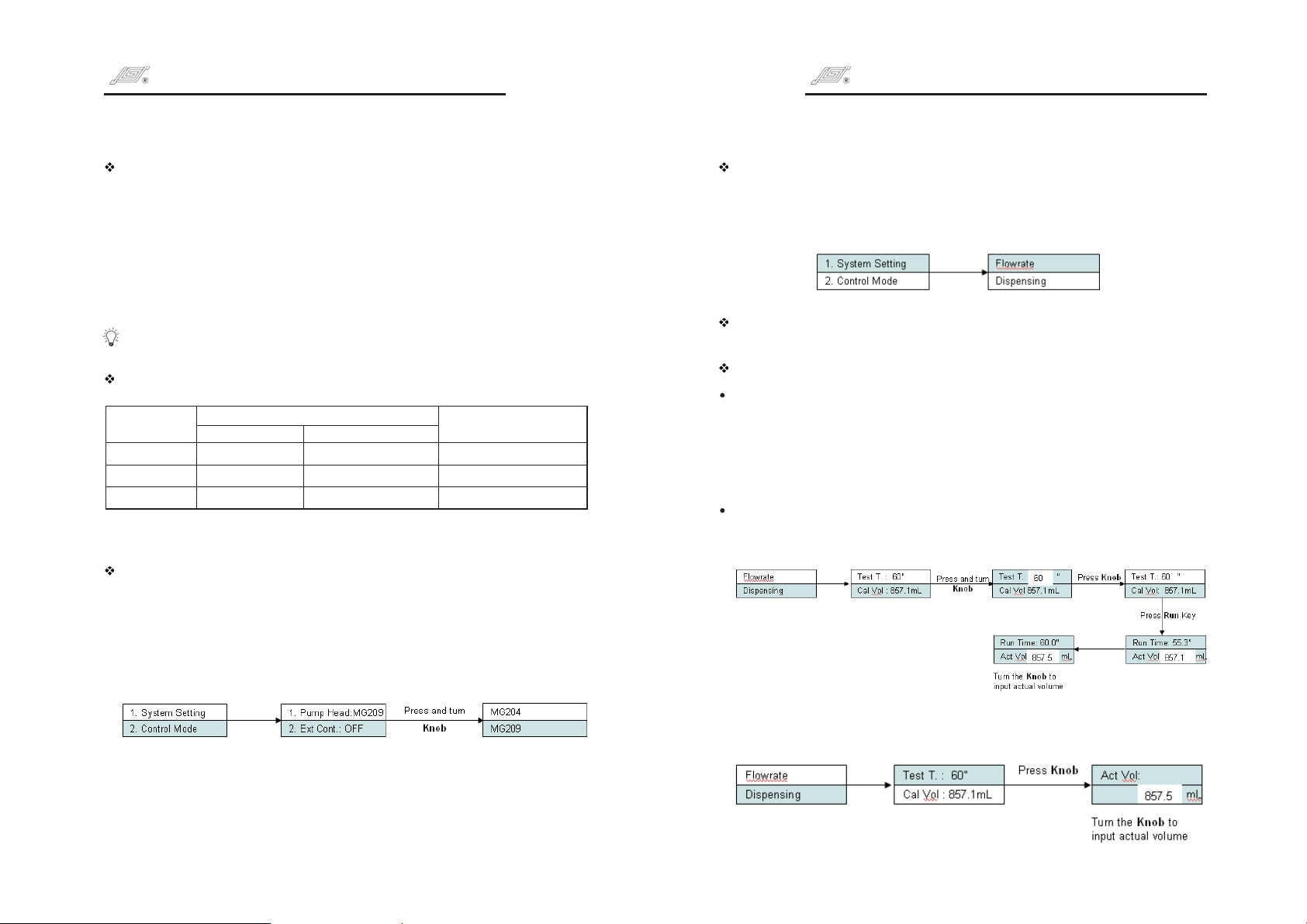
Press and turn the to highlight control mode line. Press to enter
next interface, turn to select control mode, press for confirmation.
Press not to store the selection and return to previous menu.
Exit Key
Flow Control: Turn the to adjust the flow rates.Knob
Flow Calibration
Press and turn to highlight calibration line. Press to enter next
interface. Turn to select . Press to highlight test time
line. Press again to highlight the value of time. Turn to select
test time (its range is from 30 to 1800 seconds), press for
confirmation. Press not to store the selection and return to
previous menu.
Press , the LCD displays running time and actual volume. Running
Run Key
time counts down. Turn to input actual test volume. Press for
confirmation. The calibration operation can be repeated.
Knob Knob
Knob Knob
Knob Knob
Knob Flowrate Knob
Knob Knob
Knob
Exit Key
Knob Knob
Press the to highlight Pump Head line, press again to enter pump
head selection interface, turn to select the pump head, press the
for confirmation and return to previous menu, or press not to store
Knob Knob
Knob Knob
Exit Key
the selection and return to previous menu.
5 6
If the actual volume is known in advance, enter the calibration interface and
input the actual volume directly.
Page 6
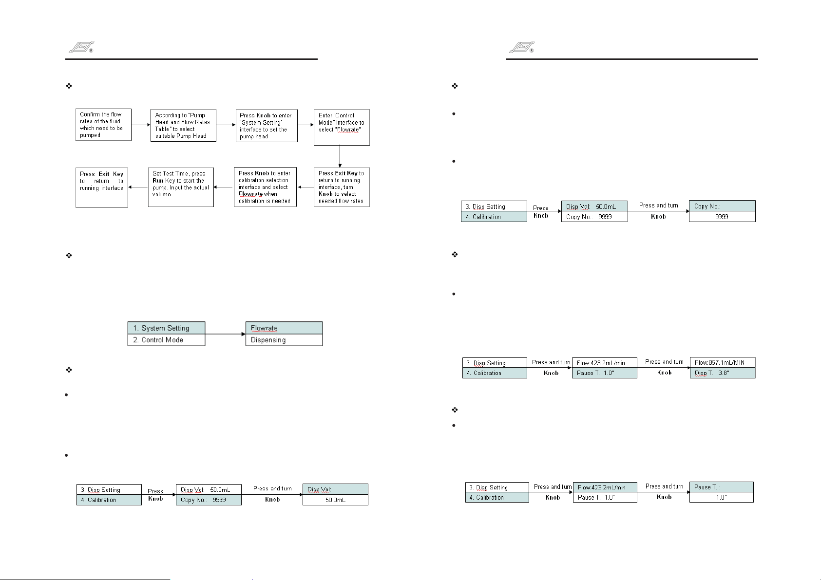
Flow Mode Operation Procedure Copy No.
the total filling number in dispensing mode. Its range is from 0 to 9999.
Micro Gear Pump Drive Operating ManualMicro Gear Pump Drive Operating Manual
Dispensing Mode Operation
Enter Dispensing Mode
Press and turn the to highlight Control Mode line. Press to enter
next interface, turn to select , press for confirmation.
Press not to store the selection and return to previous menu.
Exit Key
Dispensing Volume
The volume to be dispensed between two time intervals.
Press and turn to highlight dispensing setting line. Press to
highlight dispensing volume line. Press again to highlight the value
of the volume. Turn to select dispensing volume, press for
confirmation. Press not to store the selection and return to
previous menu.
Change the dispensing volume, the dispensing time will change
accordingly.
Knob Knob
Knob Dispensing Knob
Knob Knob
Knob
Knob Knob
Exit Key
Press and turn to highlight copy number line. Press to enter
next interface. Turn to select copy number, press for
confirmation. Press not to store the selection and return to
previous menu.
If the copy no. is “0”, the dispensing process of the pump will continue
until press or shut off the pump to stop dispensing.
Flow Rate Setting
the pump's flow rates in dispensing mode. Adjusting the dispensing
flow rates can change the dispensing time.
Press and turn to highlight dispensing flow rates line. Press
To enter next interface, turn to select suitable flow rates, press
forconfirmation.Press nottostoretheselectionandreturnto
previous menu.
Pause Time: Time Interval between every dispensing operation.
Press and turn to highlight pause time line. Press to enter
next interface. Turn to select pause time, press for
confirmation. Press not to store the selection and return to
previous menu.
Knob Knob
Knob Knob
Exit Key
Stop key
Knob Knob
Knob Knob
Exit Key
Knob Knob
Knob Knob
Exit Key
7 8
Page 7
Micro Gear Pump Drive Operating ManualMicro Gear Pump Drive Operating Manual
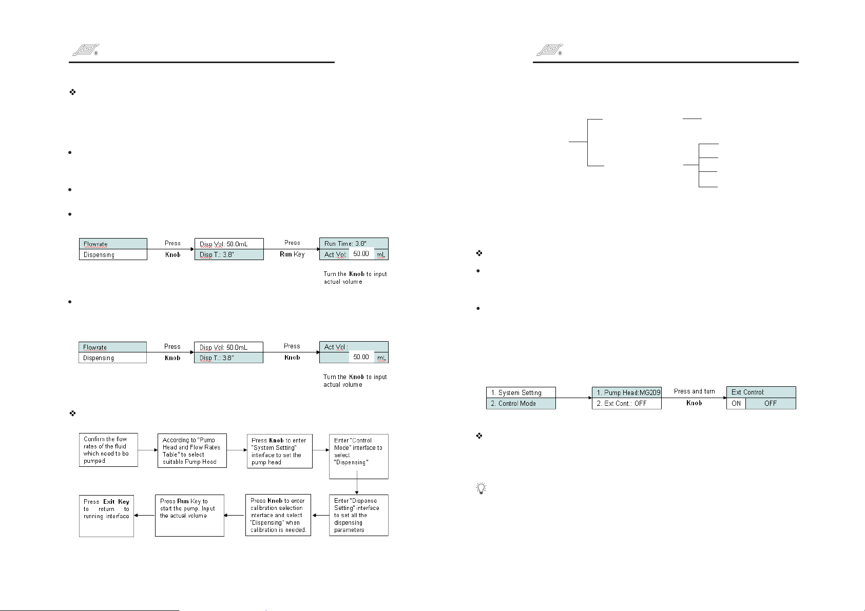
Dispensing Calibration
The parameters can not be changed under dispensing volume calibration
operation. The defaulted parameters are the parameters set under
Dispensing Setting.
Pump stops under dispense mode, press and turn to highlight
calibration line. Press to enter next interface. Turn to select
Dispensing. Press to enter next interface.
Press , the LCD displays running time and actual volume.
Run Key
Running time counts down.
Turn to input actual volume. Press for confirmation.
Knob Knob
If the actual volume is known in advance, enter the calibration interface
and input the actual volume directly.
Knob Knob
Knob
Knob
External Control
Communication
External
Control Mode
(DB15 Plug)
1.Enable the external control function.
2.These five Standard Analog Control Module need to be order separately.
External control setting
Set the pump to enable the external control or not.
On: Enable external control
Off: Disable external control
Set the external control
Press and turn to highlight the external control line. Press to
enter next interface, turn to select On or Off, press for
confirmation. Press not to store the selection and return to
previous menu.
Knob Knob
Exit Key
Control
Analog Control
Knob Knob
R 485S
4 20mA
~
0. 55V
. 10V
10
1.0 10kHz
~
~
~
Dispensing mode operation procedure
9 10
Analog Signal Control
Set “External Control” in “on” state. External control module is shown
as above.
Five kinds of standard external control module need to be ordered
separately according to special requirements.
Page 8
Terminal Definition of Standard External Control Module
1#
Analog input in 4 20 mA, 0.5 5 V, 1.0 10 V external control modules.
Control the speed of the pump. It is open in 1-10KHz. External control
module.
2#
External control start/stop input. Open or connected to low level, the
pump runs; connected to high level, the pump stops.
3#
Open
4#
Analog ground (AGND) in 4 20 mA, 0.5 5 V, 1.0 10 V external control
modules; Pulse input in pulse input external control module, Control
the speed of the pump. 10 kHz is corresponding to the max. speed.
5#
is the COM of external control start/stop signal input.
1
4
4
5
+
0.5 5V 1 10V 4 20mA,,~~ ~
Analog signal input
-
control the speed
+
1 10kHz
~
-
2
5
2
5
+
Start/stop signal
-
+
Start/stop signal
-
Micro Gear Pump Drive Operating ManualMicro Gear Pump Drive Operating Manual
1.Enable the external control function.
2.These five Standard Analog Control Module need to be order
separately.
Communication Control Mode
The pump can connect to control computer (computer, PLC, SCM)
through RS485 serial communication module (shown as below). Please
contact Longer Company for communication protocol.
5
GND
B
A
4
3
2
1
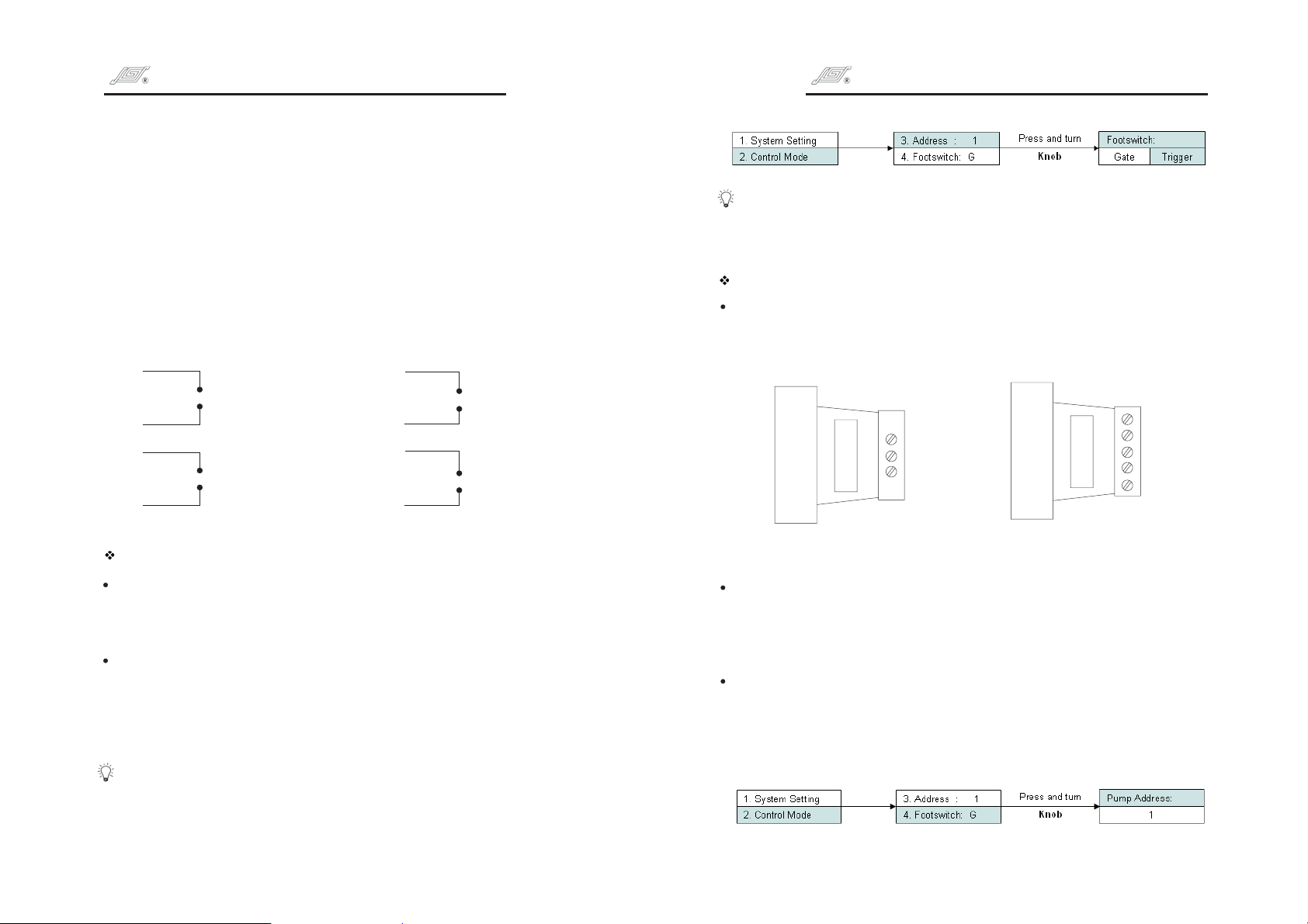
Footswitch Control
Footswitch has two kinds of working modes:
Trigger:
Press footswitch, the pump starts running; Press footswitch
again, the pump stops.
Gated:
The pump runs as long as the footswitch is pressed.
Set footswitch
Press and turn to highlight the footswitch line. Press to
enter next interface, turn to select Trigger or Gated, press
for confirmation. Press not to store the selection and return
Knob Knob
Knob Knob
Exit Key
to previous menu.
The pump identifies the Longer Footswitch automatically. When the
pump connects the footswitch, the on operating panel
Start/Stop Key
is invalid no matter the external control setting is on or off.
11 12
RS485 Communication Module Analog Signal Module
Address setting
When control computer controls many pumps through RS485 interface, it
must identify each pump's I.D. This pump I.D. should be unique. It's the
identification of this pump. Maximum 30 pieces WT3000-1FB can be
controlled through RS485 at the same time.
Set the address
Press and turn to highlight the address line. Press again to
enter next interface, turn to select Pump I.D. number, press
for confirmation. Press not to store the selection and return to
Knob Knob
Knob Knob
Exit Key
previous menu.
Page 9
Micro Gear Pump Drive Operating ManualMicro Gear Pump Drive Operating Manual
External Control Output
Pump is equipped with output port in order to monitor the status of
pump. Please see below “External Control Output Port pins Diagram:
DB9”. Output signal adopts optoelectronic isolation circuit. A pull-up
resistor and power supply are needed when using.
Terminals Definition
Start/Stop output. Pump outputs low level when it runs; pump
1#
output high level when it stops.
Pulse output, 300 3000 rpm corresponding to 1.25~12.5 kHz.
8#
4#, 6#, 7#
COM
:
Maintenance
Drive surface and pump head should be kept clean and dry because it
don't have chemical resistance to organic solvents and strong corrosive
liquids, otherwise it will shorten the life of the machine.
Technical Specifications
Functions
Acceptable Pump Head
Operation Mode
Prime
Display
External Control Input
Footswitch
External Control Output
Communication
Flow rates Function
Dispensing Function
Memory Function
Calibration
Cooling Mode
Direction
MG204, MG209, M 213
Membrane keypad and Knob
Full speed for fast filling and emptying
128 32 graphic LCD displays all the information
Control Start/Stop and flow rates under flow rates
mode
Control Start/Stop of the pump
Output the signals of Start/Stop and speed
Communicate with control computer
Deliver fluid at set flow rates
Set dispensing volume, copy number and pause
time, etc
Store all the running information automatically
Acquire higher accuracy
Heat-emitting fan
Clockwise only
G
Specifications
Flow Rate
Dispensing Volume
Copy No.
Pause Time
Flow Rate Calibration
Input Function
External
Control
Liquid to be pumped
Acceptable
Temperature
Maximum outlet pressure
(Testing medium: water)
Acceptable Liquid Viscosity
Power Supply
Power Consumption
Operation Conditions
Drive Dimensions
IP Rating
Drive Weight
Output Function
Communication
Liquid
85.7~2571.4 (Ml/min)
0.1mL~999L
0~9999, ‘0’ mean infinite cycle.
1 second~999 hours, resolution is 0.1second.
30 second~30 minutes, resolution is 1 second.
4~20 mA, 0.5~5 V, 1.0~10 V modules control
flow rates. TTL control the Start/Stop.
Output the status of Start/Stop and 1.25~12.5kHz
corresponding to 300~3000 rpm under the mode
of optical isolation.
R 485
S
The diameter of particle in liquid is smaller than 10μm
PTFE: 45~50 , PEEK 45~120
-℃ - ℃
MG204: 1.4MPa
MG209: 0.9MPa
MG213: 0.8MPa
200cst
≤
AC176~264V/90~130V, 50Hz/60Hz
150W
≤
Temperature 0 to 40
Relative Humidity <90% (No dew)
292 185 180 (mm)(L W H)
IP31
5.1kg
℃
13 14
Page 10

 Loading...