

Page 1

Document Ref:pm65\manuals\INTUITIVE_L_FLIGHT Revision:28 Dated: 20 October 2006
Software version I-L 1.2
Panel mounting load / weight indicator / controller
INTUITIVE-L
Connection details, scaling and general information
Digital Scaling and calibration
User friendly, time-saving design
Fast installation and commissioning
London Electronics Limited
Thorncote Road, Near Sandy, Bedfordshire SG19 1PU
Tel +44(0)1767 626444 Fax +44(0)1767 626446
www.london-electronics.com [email protected]
Page 2

.
Page 3

Alphabetic Index
Alarm board Configuration 14
Alarms, how to set 15
Analogue Output configuration 17
Analogue output, how to set 18
Calibration method selection 6
Calibration - Direct method 8
Calibration - Theoretical method 7
Calibration - Tamper detection 12
Connections 5
Count-By (last digit round-up) adjustment 9
Decimal point position selection 7 & 8
Declaration of Conformity 29
DeviceNet output option 20
Failsafe alarm setting 10
Filter time constant selection 9
General description 3
Getting Started 4
Hysteresis adjustment 15
In-Flight compensation facility 16
Installing options 13
Introduction 1
Input connection examples 5
Linearisation facility 10
ModBus RTU & RS485 output option 20
Peak / Valley detection and memory 11
Programme memory facility 21
Reset command 12
Revisions record 23
Serial Communications 19
Specifications 22
Tare Command 11
Troubleshooting 25, 26
Zero-Drift automatic compensation feature 12
Warnings 2
WEEE advice 28
Page 4

-
Page 1
-
Introduction
Please contact us if you need help, if you have a complaint, or if you have
suggestions to help us improve our products or services for you.
If you contact us about a product you already have, please tell us the full model
number and serial number, so that we can give you accurate and fast help.
This product has a 2 year warranty. We will put right or replace any meter
which is faulty because of bad workmanship or materials. This warranty does
not cover damage caused by misuse or accident.
IMPORTANT
If this equipment is important to your process, you may want to buy a spare to
cover possible failure or accidental damage in the future.
This is because at some times, for example during our factory shutdown periods,
you may have to to wait several weeks for an equivalent replacement. Or, we
may have no stock at the time you urgently need it.
You may also need to pay extra carriage charges if you want a fast, guaranteed
courier service. Warranty repairs or replacements are normally returned with a
standard courier service.
We do not offer any compensation for losses caused by failure of this instrument.
If you do not agree with these conditions, please return this item now, in unused,
clean condition, in its original packaging and we will refund the purchase price,
excluding any carriage paid.
We thought you’d prefer to know about possible delays and extra charges now,
rather than during a panic.
We always try to improve our products and services, so these may change over
time. You should keep this manual safely, because future manuals, for new
designs, may not describe this product accurately.
We believe these instructions are accurate, and that we have competently designed
and manufactured the product, but please let us know if you find any errors.
Page 5

Page 2
Safety First ..............Don't assume anything............. Always double check.
If in doubt, ask someone who is QUALIFIED to assist you in the subject.
Warnings
Please carefully read all warnings and ONLY install the meter
when you are sure that you’ve covered all aspects.
!
* Connect the meter according to current IEE regulations and separate all
wiring according to IEC1010.
* Power supplies to this equipment must have anti-surge (T) fuses at 125mA
for 230V supply, 250mA for 110V supply or 1A for DC supplies in the
range 11-30VDC.
* Check that the model number and supply voltage suit your application before
you install the meter.
* Don’t touch any circuitry after you have connected the meter, because
there may be lethal voltages on the circuit board.
* We designed this meter for Installation class II service only. This means
it has exposed electrical and power terminals, so you must install it in an
enclosure to protect users from electric shock.
* We designed this meter for Pollution-Degree 2 environments only. This
means you must install it in a clean, dry environment, unless it has extra
protection from a splashproof cover, such as our SPC4
* Only adjust on-board switches or connections with the power turned off
* Make sure all screw terminals are tight before you switch the meter on.
* Only clean the meter with a soft damp cloth. Only lightly dampen with
water. Do not use any other solvents.
Page 6
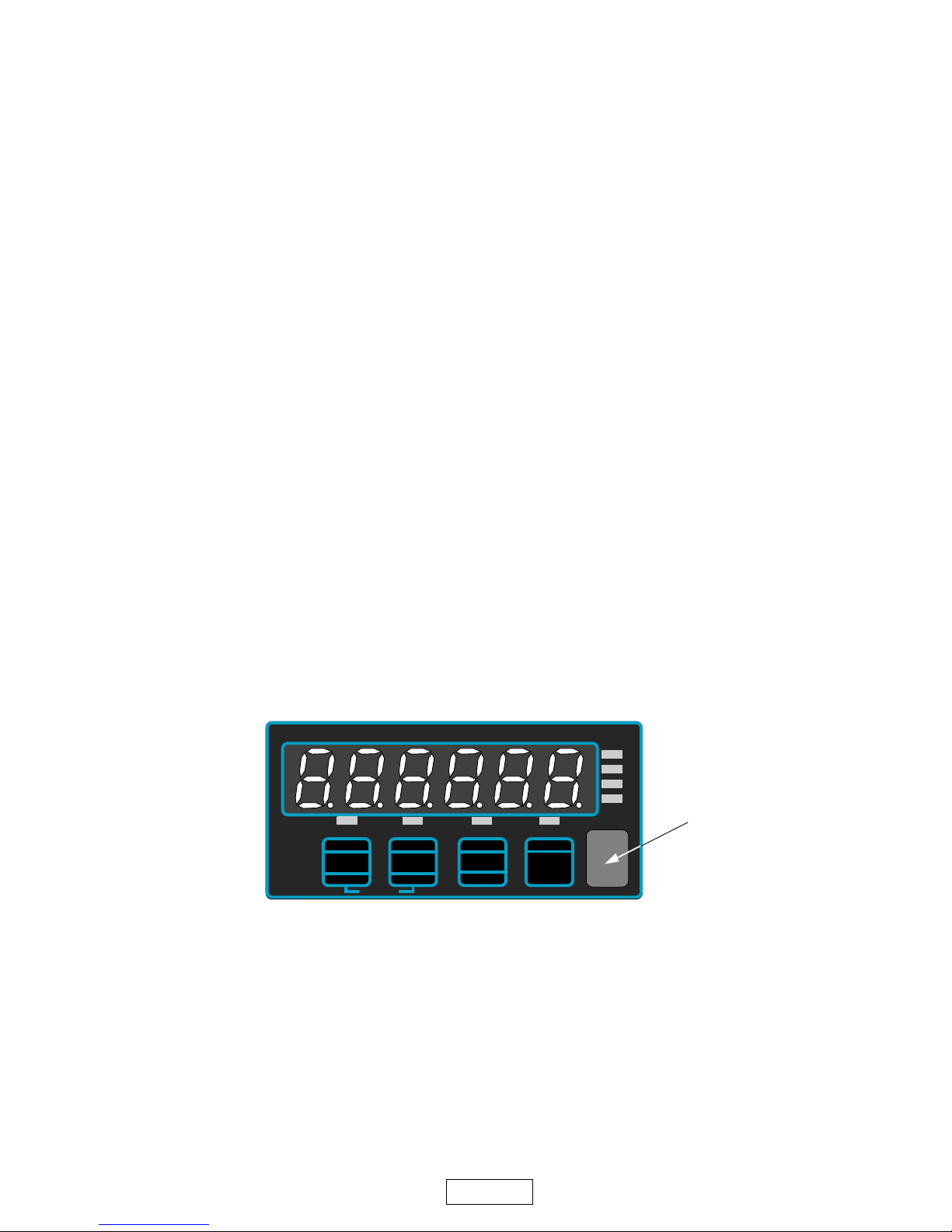
General Description
This meter is simple to configure. It is easy to use because it has no menu system.
Look at the front panel below... to adjust ZERO you press the ZERO button, to
adjust Span you press the SPAN button, to adjust Analogue Output you press the
ANALOG button, to adjust Alarms you press the ALARM button. There is no
need to spend time learning a complex menu system.
The meter’s main function is to display physical variables, such as weight,
load, force and torque. It provides you with a 10V regulated excitation supply,
capable of powering up to four 350 Ohm loadcells. This can be used in 4 wire
or 6 wire installations You can linearise signals with the 10 point userconfigurable lineariser, a standard feature.
Peak and valley memories allow you to view the minimum and maximum recorded
measurements.
The meter can give alarm outputs, scaled and isolated analogue output and isolated
serial data retransmission when fitted with option boards.
The front panel has a 6 digit, 7 segment window for displaying the measurement.
It allows decimal point and minus sign characters to be included and has 4
alarm annunciators to show the status of each alarm relay.
The front panel pushbuttons each have an LED to show which setting is being
altered at any time. A clear protective window is provided, behind which you
can fit one of our ‘Units-of-Measure’ labels, to identify the reading as Kg, or
Nm, or Bar, etc.
2 lockout switches on the rear of the meter save your configuration and alarm
settings in memory, which has a 10 year guaranteed storage period. If the lockout
switches are not set ON, your settings could be accidentally altered.
DIGIT
Min.
ZERO
SPAN / dp
ZERO
SPAN & d.p.
MAX / MIN
TARE
ALARMS
OK
s
RESET
s
OUTPUT
AL1
AL2
AL3
AL4
0% O/P 100% O/P
Lineariser
Max.
“Units of
measure”
window
Page 3
Page 7

Page 4
Getting Started
First, please check that the display will suit all the requirements of your
application. Page 4 has some important warnings - please check that all warnings
are covered.
If you have analogue output or alarm relay options, you may need to configure
their boards before installing the meter in a panel. See the separate sections in
this manual for those options.
Check that your panel cutout is correct , 92mm wide, 45mm high. You must fit the
meter in a protective enclosure for installation class II service. Remove the 2
screws holding the U clamp at the rear of the case. Slide the meter into the cutout
and re-fit the U clamp and screws. Tighten the screws just enough to hold the
meter firmly in place and make sure the sealing gasket is evenly held between
the panel and the bezel.
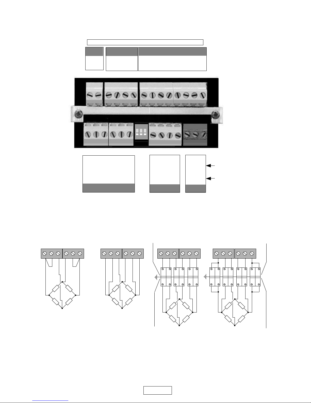
Connect the signal and power cables, to the appropriate screw terminal connectors.
Check that you are using the correct terminals or you may cause damage to the
meter. Do not connect any output or alarm cabling yet.
Apply power, and confirm that the meter illuminates all segments for a few
seconds and then shows the software version “I-L X.X” briefly (The X numerals
depend on version).
The calibration lockout switch should be OFF to allow you to change the meter’s
settings. Set the scaling to suit your system, using one of the scaling methods
described in this manual. Check that the meter responds correctly. Now, adjust
your analogue output settings, if necessary, and alarm settings. Use a DVM of
sufficient precision to check that the analogue output is operating as required,
and use a continuity tester to check that the relay contacts operate correctly.
Switch the meter off, and check alarm relay contact status. The alarm lockout
switch should be OFF to allow you to change the meter’s alarm settings.Check
that the contact status suits your system, in conditions of power loss to the meter.
When you have checked all settings, you can connect the alarm relay and analogue
output cables, to check correct system operation
Remember to set the lockout switches ON when you have finished , to prevent
accidental loss of your settings.
Page 8
Excitation -
Sense -
Signal -
Signal +
Sense +
Excitation +
INPUT
REMOTE
Earth
Neutral
Line
AL1
AL1
AL2
AL2
AL3
AL3
AL4
AL4
ALARM RELAY OUTPUTS
POWER
Serial
Output
Cabling should be screened and routed away from noise-carrying cables and
machines to reduce interference. The screen can be connected to power earth if
it is not already grounded at the sensor end.
These connectors are only used when options are fitted
Connections - See also page 23
Neg.
Pos.
E - +
123 4 5 6
Analogue
Output
Common
Tare
Peak/Valley
Reset
IMPORTANT!
Set the Lock switches to their ‘ON’ position after setup, to save your settings.
REAR VIEW
Mains Power model
DC Power model
1 2 3 4 5 6 7 8 9 10 11 12 13
14 15 16 17 18 19 20 21 22 23 24 25 26 27
123 4 5 6 123 4 5 6 123 4 5 6
Calibration Method Switch
Alarm Lock Switch
Calibration Lock Switch
Page 5
Hazardous
Area
Hazardous
Area
6 wire Hazardous area schemes. Depending on barriers
chosen, and the number of loadcells used, the excitation
voltage will need to be set appropriately. Our technical
sales team will be happy to advise you. Please note that
we are not in a position to recommend barrier types.
Basic 4 wire system 6 wire system
Safe
Area
Safe
Area
ON
See pages for
different types
Page 9

Choosing a Calibration Method
You can choose one of two calibration methods.
All calibrations are saved by switching ‘ON’ the lockout switch when you are
finished.
1) Calibration without an input signal.
This is ‘THEORETICAL’ Calibration (not available with MEM-08 option)
You can use this method if you know the calibration of your sensor. Assume your
sensor gives 0-22mV for 0-250 kg.
You should first select the ‘THEORETICAL’ calibration switch position on rear
of the meter.
Then , using the buttons on the meter, you will tell the meter what 0% input signal
level will be (0mV) and what 0% reading value will be (0). Next, tell it what
100% input signal level will be (22mV) and what 100% reading value will be
(250)
The Multi-Point linearisation facility is not yet available with this method of
calibration. A separate page covers this calibration method in detail.
2) Calibration by injecting signals into the meter, either from a calibrator or
a sensor installed in a system. This is ‘DIRECT’ Calibration.
Select the ‘DIRECT’ calibration switch position on the rear of the meter.
Inject a signal to the meter equal to 0% of signal range. (If the signal is from a
loadcell, you don’t need to know the value of signal, only what the meter should
read. Assume your loadcell covers 0-250 kg) Use the buttons on the meter to tell
the meter what to read when no load is applied to the sensor, 0kg
Now apply a signal 100% of range (If the signal comes from a loadcell, apply
full capacity load, if possible. If you can’t apply 100% of load, apply a lesser,
known load. Calibration accuracy will be better with larger signals) Use the
buttons on the meter to set reading to 250, or the lesser load you apply.
A separate page covers this calibration method in detail.
Page 6
Page 10

‘THEORETICAL’ Calibration
Set switch 1, near the input connector ON and switch 3 OFF
1) How to set SPAN and DECIMAL POINT
Press the SPAN button for 3 seconds.
You’ll see ‘In HI’ briefly, then a value, with one digit brighter than the other.
This is 20.000 for a 20mV input signal, or 10.000 for a 10mV input signal, and
so on. If the value is correct, press the ‘OK’ button, otherwise use the ‘DIGIT’
key to select digits, and the ‘UP’ or ‘DOWN’ arrow keys to alter. When correct,
press the ‘OK’ button.
‘rd HI’ appears briefly, then a value, with one digit brighter than the other. This
is what will be displayed for the IN HI input. If the value is correct, press the
‘OK’ button , otherwise use the ‘DIGIT’ key to select digits, and the ‘UP’ or
‘DOWN’ arrow keys to alter . The Decimal point position may be set after the
most significant digit has been selected. When correct, press the ‘OK’ button.
2) How to set ZERO
Press the ZERO button for 3 seconds. You’ll see ‘IN LO’ briefly, then a value,
with one digit brighter than the other. This is 0.000 for 0mV input signal, 3.000
for a 3mV input signal, etc. If already correct, press the ‘OK’ button. Or, use
the ‘DIGIT’ key to select digits, and the ‘UP’ or ‘DOWN’ arrow keys to change.
When correct, press the ‘OK’ button.
You’ll now see ‘LO rd’ briefly,then a value, with one digit brighter than the
other. This is what will be displayed for the IN LO input. If already correct,
simply press the ‘OK’ button. Or, use the ‘DIGIT’ key to select digits, and the
‘UP’ or ‘DOWN’ arrow keys to change. When correct, press the ‘OK’ button.
IMPORTANT!
Set lockout switch 3 to its ‘ON’ position after setup, to save your settings.
Do NOT move switch 1 or 2. If your readings change when you move switch 3, make a brief
connection between terminal 7 and 10 to clear any tare offsets.
Page 7
Page 11

‘DIRECT’ Calibration
Please set switches 1 and 3 next to the input connector to OFF
You must have the meter connected to power and a steady input signal before
you start.
How to set the Span Calibration and Decimal Point position
1) Apply 100% Cal. load, and ensure it is steady before proceeding
2) Press the SPAN Button for 3 seconds
3) The SPAN LED should flash
4) Set the display to read the load you are applying, by pressing UP/DOWN
and DIGIT Keys. To change the decimal point position, use the DIGIT
button to brighten the left-hand digit. Then, one more push of the DIGIT
button will allow you to move the decimal point with the UP/DOWN
buttons.
5) When display correctly set, press OK
How to calibrate Zero
1) Apply zero load and ensure system is steady before proceeding
2) Press the ZERO Button for 3 seconds
3) The ZERO LED should flash
4) Set the display to read 0 , or the desired reading for this signal, by
pressing DIGIT SELECT and theUP/DOWN Keys
5) Press OK when done
That completes the calibration of your meter.
IMPORTANT!
Set lockout switch 3 to its ‘ON’ position after setup, to save your settings.
Do NOT move switch 1 or 2. If your readings change when you move switch 3, make a brief
connection between terminal 7 and 10 to clear any tare offsets.
Page 8
Page 12
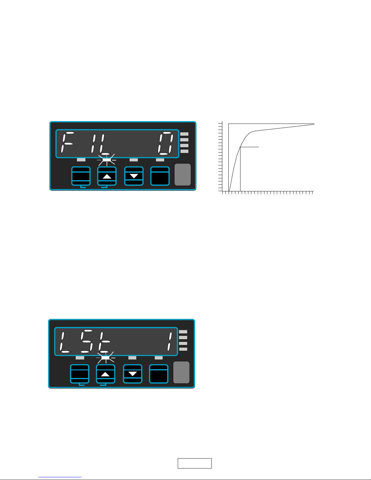
LSt = 1 Best resolution, but most sensitive to noise. Sequence 0,1,2,3,4,5,6 ...
LSt = 2 Sequence 0,2,4,6,8,0...
LSt= 5 Sequence 0,5,0,5...
LSt=10 Sequence 0,10,20,30...
LSt=20 Sequence 0,20,40,60...
LSt=50 Lowest resolution, least sensitive to noise Sequence 0,50,100,150...
Filter and Last Digit Roundup
The alarm LOCK switch must be OFF to access these variables. Press the OK
button 5 times to access the filter time constant, which is expressed in seconds.
You can use the filter to improve your display stability with fluctuating input
signals. Use the UP and DOWN buttons to select a time constant in the range 0 to
5 seconds. Bigger time constants give more stability but slower response, and
affects display, analogue, serial and alarm outputs. Press OK when selected.
The Time constant of this digital filter is very similar to the time constant of an RC filter where
T=RC . The time constant is the time it takes for the display to reach 63 % of its final reading value,
after a step change on the input. You can see that if you select a 1 second filter time, it will take
several seconds for the meter to reach its final value. To give improved response to large step
changes, we momentarily cancel the filter action for stable input step changes of over 64 counts,
and then re-apply the filter to maintain stability.
Another function which can give you a more stable display, with less flicker is
the LAST DIGIT ROUNDUP.
After the filter setting, the display will show LSt and a number. This number sets
the increments by which the meter will change its reading.
DIGIT
Min.
ZERO
SPAN / dp
ZERO
SPAN & d.p.
MAX / MIN
TARE
ALARMS
OK
RESET
OUTPUT
AL1
AL2
AL3
AL4
0% O/P 100% O/P
Lineariser
Max.
time...
Input signal step
Display settling curve
63% of final
settling value
t
0
t
c
DIGIT
Min.
ZERO
SPAN / dp
ZERO
SPAN & d.p.
MAX / MIN
TARE
ALARMS
OK
RESET
OUTPUT
AL1
AL2
AL3
AL4
0% O/P 100% O/P
Lineariser
Max.
Use the UP/DOWN buttons to
select a roundup value, and
accept by pressing OK.
Page 9
Page 13

ZERO
SPAN
Point3
Point4
Point5
Point6
Point7
Point8
Point9
PointA
APPLIED SIGNAL
DISPLAY
Page 10
Using the Lineariser
You can enter up to 10 calibration points, to generate a curved function between input
signal and displayed value. Each point MUST be greater in value than the previous
one and the meter must be set for DIRECT calibration method.
(Note - linearising is not available on MEM-08 option meters or meters set for
THEORETICAL calibration)
1) Calibrate the first two points using the ZERO pushbutton for the lowest
input load (0) and SPAN pushbutton for the 2nd input load, using the direct
calibration routine. Do not calibrate SPAN with 100% input !
2) Apply the 3rd input load and then press both ‘LINEARISER’ Buttons.
Display should confirm by saying POINT3.
Adjust the reading to the desired value using the DIGIT SELECT and the
UP/DOWN pushbuttons.
Press OK when done.
3) Apply the 4th input load and then press both ‘LINEARISER’ Buttons.
Display should confirm by saying POINT4.
Adjust the reading to the desired value using the DIGIT SELECT and the
UP/DOWN pushbuttons.
Press OK when done.
You can repeat this process for as many other calibration points you wish to apply,
up to a maximum of 10.
There is no time limit with these settings, so you can take as much time as you need to
adjust each point. But, power must not be removed from the meter during the procedure,
or your settings will be corrupted.
IMPORTANT!
Set lockout switch 3 to its ‘ON’ position after setup, to save your settings.
Do NOT move switch 1 or 2. If your readings change when you move switch 3, make a brief
connection between terminal 7 and 10 to clear any tare offsets.
Page 14

Features
Peak and Valley Detection (Maximum/Minimum Reading View)
The meter can store the lowest and highest reading values in memory. You can
see these values if you press the MAX/MIN front panel button, or by using remote contact closure switches. The first press shows peak, with the upper left
hand indicator bar lit (marked ‘Max.’). The second press shows valley, with the
lower left hand indicator lit (marked ‘Min.’). The display returns to the running
value after 2 or 3 seconds. To reset the memory, press the RESET button for
more than 3 seconds while peak or valley is being displayed. Peak and Valley
values are not stored if you switch the meter off.
How to use the MAX/MIN button to view Peak or Valley
1) Link terminal 7 to terminal 9 (not necessary if MEM-08 option fitted)
2) Set lockout switch ‘ON’
3) Press UP arrow key (MAX/MIN)for peak, valley, normal
Remote contact closure viewing of Peak/Valley (Not with MEM-08 option)
1) Connect a normally-open contact closure switch between terminals 7 and 9
2) Set the calibration lockout switch ‘ON’
Tare Command
You can force the reading to zero by pressing the front panel tare switch for 2 to
3 seconds, or by applying a remote contact closure. Following readings will be
the ‘net’ value, offset by the reading at the time the tare switch was operated.
The tare value is stored in non-volatile memory. The ZERO led will light to
show you that the unit has been tared.
Front Panel key Taring
1) Link terminal 7 to terminal 8 (not necessary if MEM-08 option fitted)
2) Set calibration lockout switch ‘ON’
3) Press ZERO key for 3 seconds to tare display. The ZERO led will light to
show you that the unit has been tared.
To reset the tare from the front panel, press the Tare button and the Reset button
together. The ZERO led will go out when tare has been cleared.
Remote contact closure taring (Not available on MEM-08 option meters)
1) Connect a normally-open contact closure switch between terminals 7 and 8
2) Set calibration lockout switch ‘ON’
Page 11
Page 15

Page 12
Features - contd.
Automatic Zero-Drift Compensation
This feature is useful in applications where your meter reads zero most of the
time. It cancels long-term zero drift caused by ageing, temperature change, etc.
If the reading is within 7 counts of zero for around 100 seconds, the reading will
go to zero without changing basic calibration. The correction is not stored
when the meter is switched off and is cleared if you press the front panel
RESET button for more than 3 seconds. To activate this feature, set the display
value at 0% input to MINUS ZERO ( -0)
Calibration Counter / Tamper detector
An internal totaliser counts each calibration. The ‘CAL XX’ value appears for a
second or two after you switch the meter on. The number starts at 00 and can go
up to FF (255 counts). It doesn’t count changes of setpoints, or changes of filter
value or count-by value . It stores the total in non-volatile memory which can’t
be reset, so is useful for keeping track of the meter’s calibration history.
Reset Command
The reset command clears any stored peak or valley data, any tared offsets
and any in-flight compensation data. It may be accessed either from the front
panel or by external contact closure command.
Front Panel key reset command
1) Link terminal 7 to terminal 10 (not necessary if MEM-08 option fitted)
2) Set calibration lockout switch ‘ON’
3) Press Down Arrow key to reset display.
For Tare reset, you must press the Tare button AND the Reset button together.
For Peak/Valley reset, you must activate the reset key while a peak or valley
value is being displayed.
Remote contact closure resetting (Not with MEM-08 option meters)
1) Connect a normally-open contact closure switch between terminals 7 and 10
2) Set calibration lockout switch 3 ‘ON’
Page 16
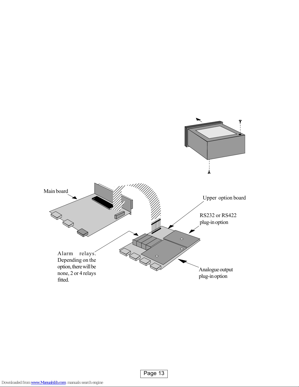
How to install option boards
If you want to open the meter to install or modify option boards, follow these
steps...
1) Switch off power to the meter and unplug all connectors.
2) Unclip the front bezel. This is easier if you squeeze the top and bottom of
the case, near the front.
3) Remove the small screws shown in the diagram. If the meter doesn’t yet
have an output option board, the top screw may not yet be fitted.
4) Slide the electronic boards out throught the front of the case. You can easily
separate the upper option board from the
main board. We strongly suggest that you
use anti-static precautions toprevent
damage to the semiconductors.
The board assemblies will look something like this...
The analogue output and RS232 or RS422 plug-in option boards are fixed to the
upper option board with white plastic pillars. You must apply a firm force when
fitting or removing these options.
Always be careful to connect the pins to sockets accurately. When reassembling,
make sure option boards are firmly fixed to the upper option board. When the
boards are replaced in the case, secure them again with the two small black
screws.
Plug- In
Microprocessor
RS232 or RS422
plug-in option
Analogue output
plug-in option
Alarm relays.
Depending on the
option, there will be
none, 2 or 4 relays
fitted.
Upper option board
Main board
Page 13
Page 17
Open Contacts
Closed Contacts
Energise
De-energise
Energise
De-energise
Energise
De-energise
Energise
De-energise
Alarm Board Configuration & Adjustment
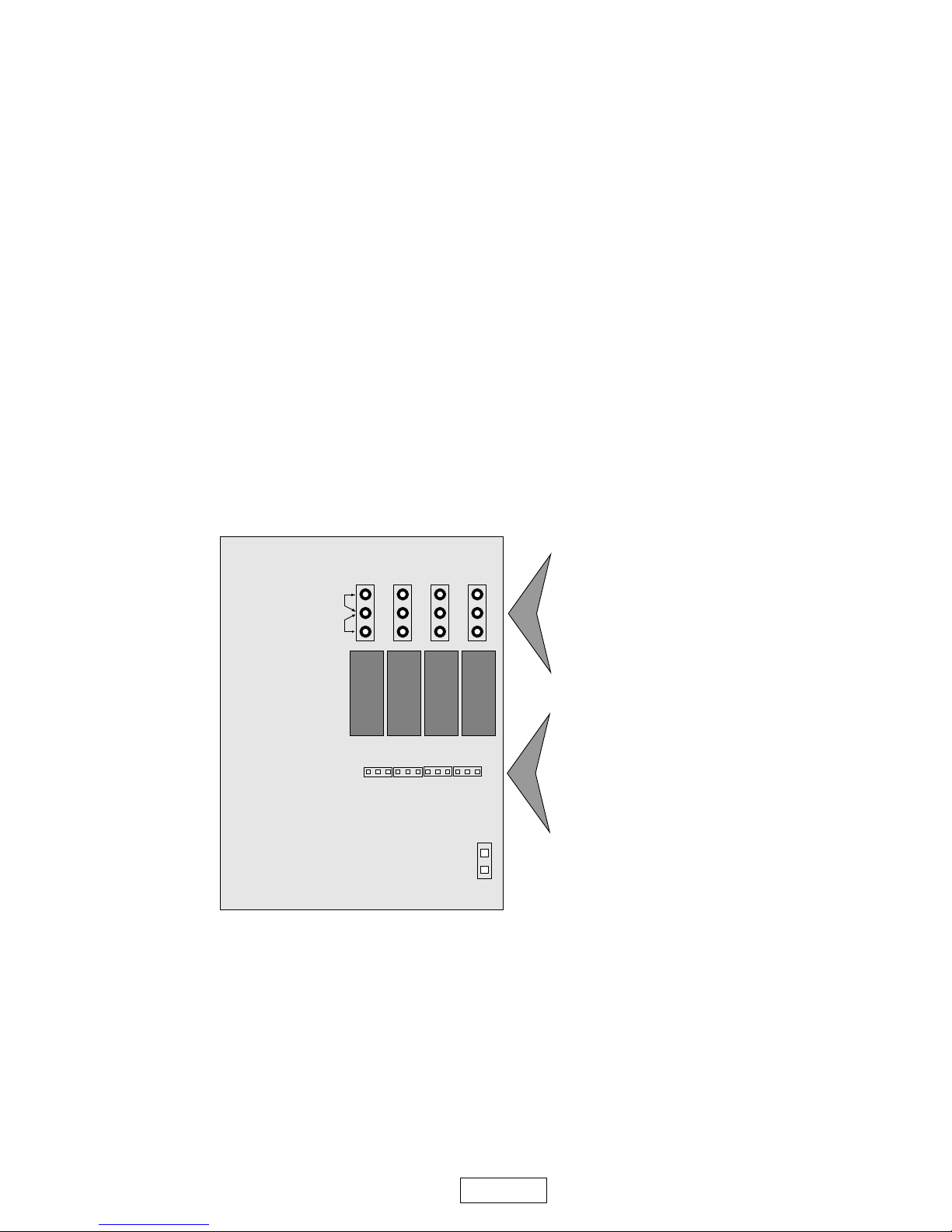
For failsafe operation (where contacts open on alarm or when power is lost to
the meter) set the jumpers for OPEN CONTACTS and DE-ENERGISE on alarm.
To access to the alarm board, first remove power from meter, including any
power which might be on the alarm output circuitry.
Look on the top and bottom surfaces of the case, near the rear. You will see two
small screws, one on each surface. Remove both screws. Now, clip off the front
bezel and slide the meter assembly carefully out via the front of the case.
The relay board plugs into the main board. Gently separate the two boards.
Select relay output contact
status, when relays are
de-energised (power removed
from meter) by placing these
jumpers...
and set these jumper to make
the alarms energise or deenergise on trip. De-energise
means you will get an alarm if
power is lost to the meter.
When you have set the jumpers, refit the board to the meter and carefully slide
the assembly back into the case.
Fit the two small board screws to the top and bottom surfaces.
Page 14
AL1
AL2
AL3
AL4
Page 18
Alarm settings (set alarm lockout switch OFF of you want to make changes)
Press the ALARMS button briefly, to view each of the 4 alarm settings (each
press will light, in turn, AL1, AL2, AL3 and AL4 LEDs). Set the middle switch
near the input connector (Alarm LOCK) to OFF if you want to change alarms.
To change alarm settings, choose an alarm as shown above, then press the ALARM
key for more than 3 seconds. You will see one digit brighter than the others. You
can change its value using the UP/DOWN buttons. Select other digits with the
DIGIT SELECT pushbutton.
The alarm type is set with the left-hand character: ’H’ for HIGH alarm action,
‘L’ for LOW alarm action, or ‘o’ for NO alarm action. You can change this with
the UP/DOWN buttons. Press OK when set.
The alarm control method is identified with a prompt, and you can change this to
suit your requirements. After the prompt, is the value which you can set.
The hysteresis value is related to your measurement, so if you have a high alarm,
set to 500, and you set the hysteresis value to 7, the alarm will occur when the
meter reading reaches 500, and will reset when the meter reading falls to 493.
Remember to set the Alarm lockout switch to ON when you have finished.
DIGIT
Min.
ZERO
SPAN / dp
ZERO
SPAN & d.p.
MAX / MIN
TARE
ALARMS
OK
RESET
OUTPUT
AL1
AL2
AL3
AL4
0% O/P 100% O/P
Lineariser
Max.
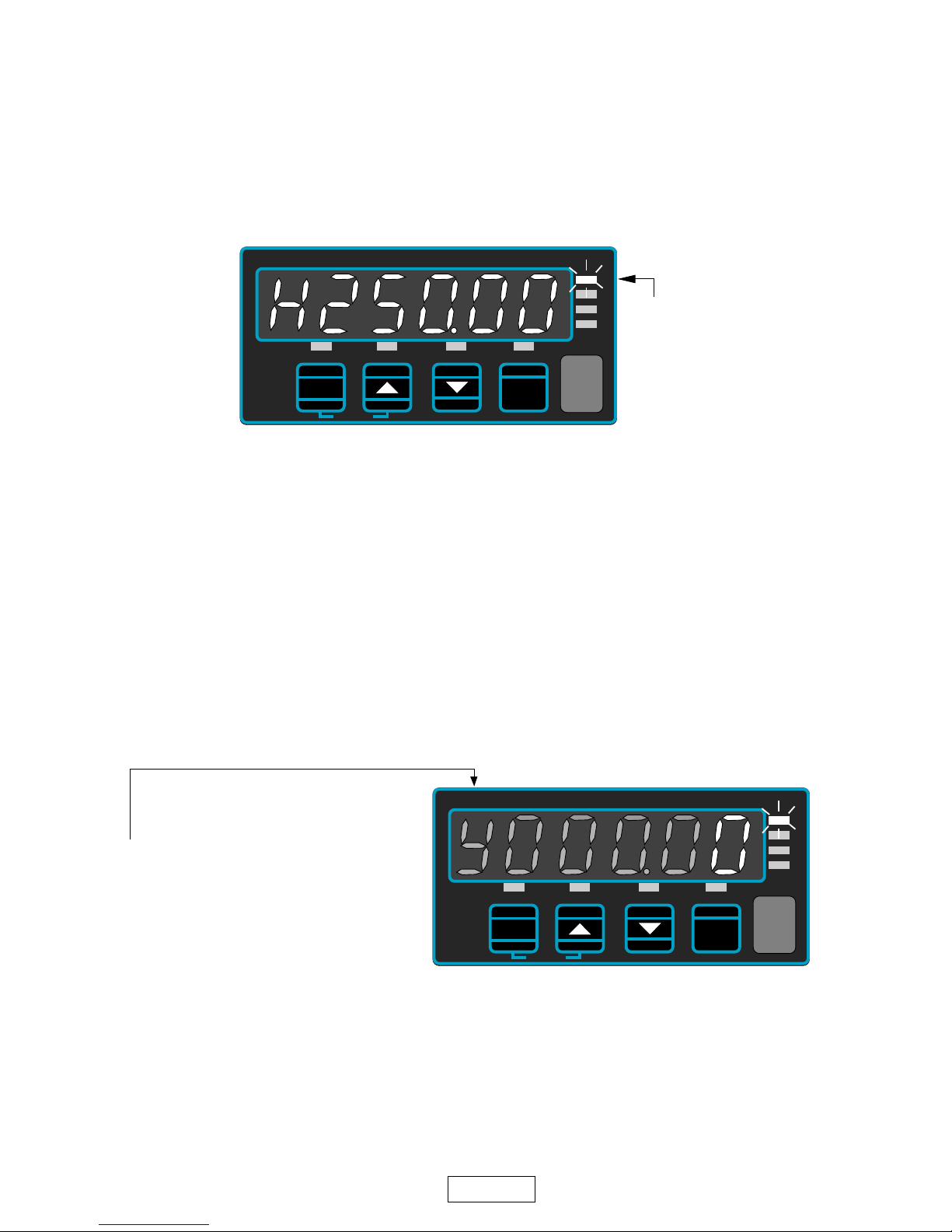
Alarm channel LED will
flash.
Here, we see that Alarm
1 is a high alarm with its
setpoint at 250.00
DIGIT
Min.
ZERO
SPAN / dp
ZERO
SPAN & d.p.
MAX / MIN
TARE
ALARMS
OK
RESET
OUTPUT
AL1
AL2
AL3
AL4
0% O/P 100% O/P
Lineariser
Max.
Page 15
Y = Normal hysteresis (default)
C = Constant inflight offset
F = Fully automatic inflight.
Page 19
In-Flight Compensation
You can configure the meter to have in-flight compensation, which can improve
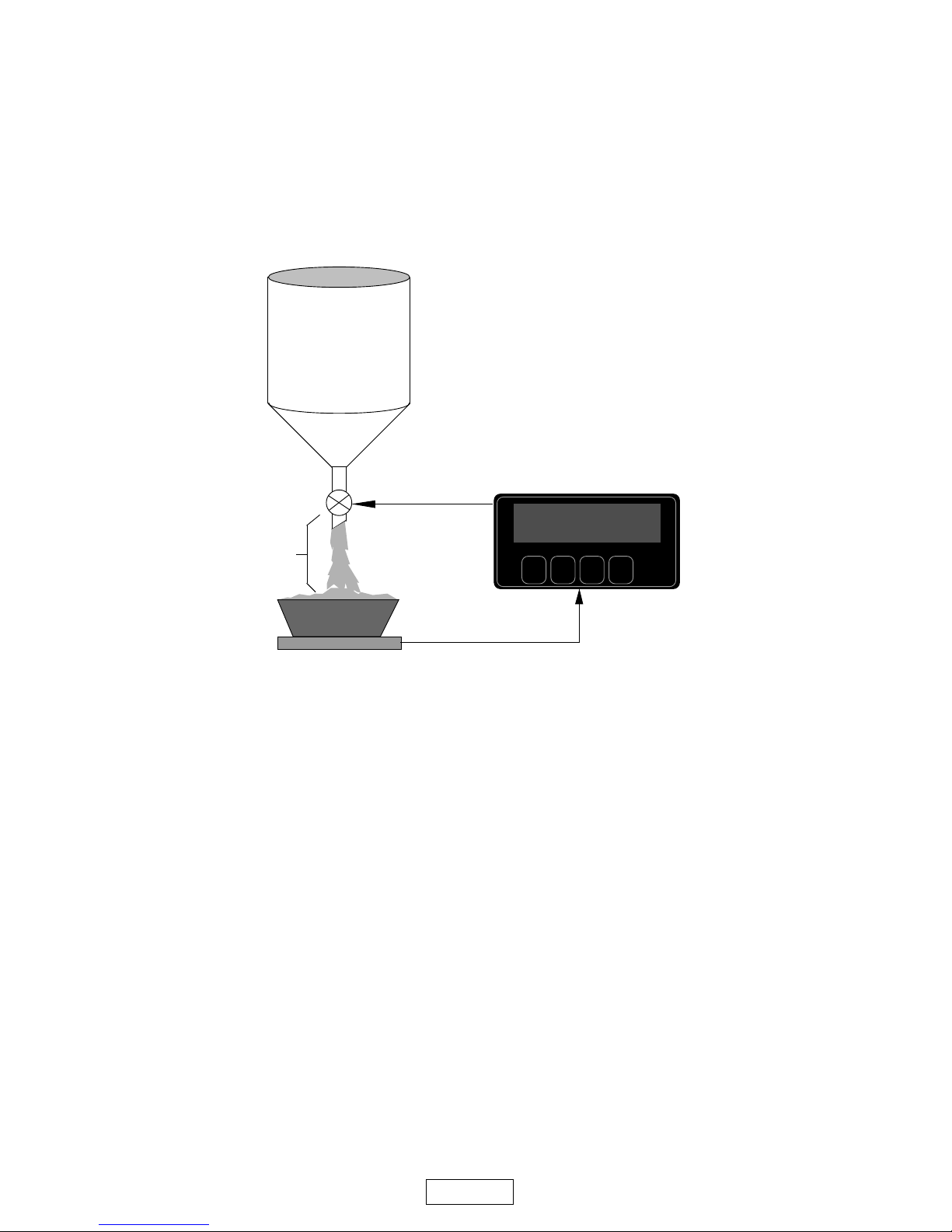
alarm accuracy in some applications. Here’s how it works....
Imagine you have a storage container and you want to empty material from that
container into a bin.
If you know the inflight error, say it is 10.7 kg, you can type it in as C0010.7
If you want the meter to calculate the inflight compensation for you, set F00000.
The meter will compare the desired setpoint level to the actual final fill or
empty weight, or position, and compensate for any calculated error for the next
cycle. You can also pre-load your estimated offset into the Fully automatic mode.
Set FXXXXX where XXXXX is your estimate of inflight material weight.
The meter automatically adapts the offset after each operation. You can view the
meter’s revised compensation value in the FXXXXX value.
For the first alarm, the meter will correct for 100% of the measured error, to get
as close to desired action as possible. Then, each time the alarm occurs, it will
correct for 25% of the previous smaller error, to reduce the effects of material
variations.
Remember to set the Alarm lockout switch to ON when you have finished.
Material ‘In Flight’
Shutoff Valve
Weighing platform
Bin being filled
Storage container
250.0
Kg
weight signal
Alarm
When the bin reaches the desired
weight, the meter will switch off the
shutoff valve. But, some material is still
falling into the bin, and will add to the
weight. This gives an overweight error.
Page 16
Page 20
Analogue Output Configuration
We always set the meters to suit any requests on your order, so you should not
need to adjust the analogue board. If you didn’t specify ranges, but ordered
option ‘ANI’, the meter will be set for 4-20mA output. If you ordered ‘ANV’ it
will be set for 0-10V.
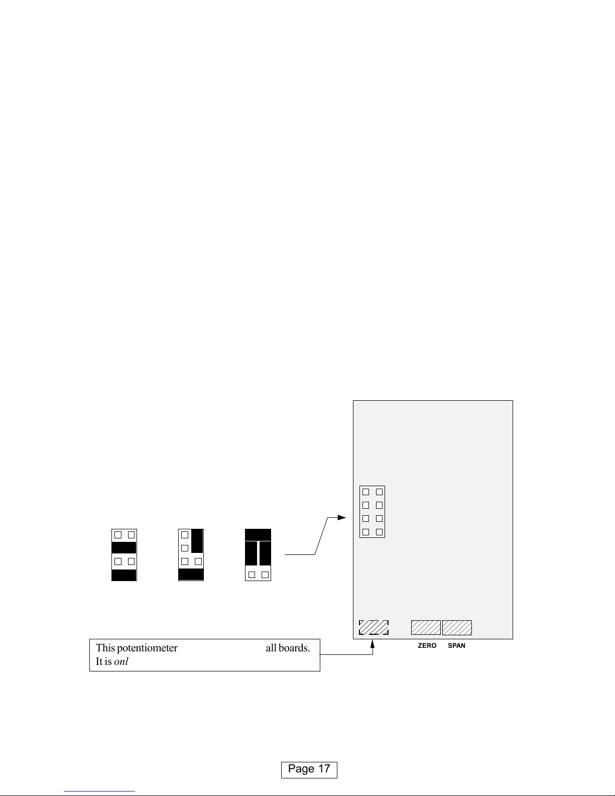
If you want to change a range, for example from 0-10V to 4-20mA, the zero and
span potentiometers must be adjusted to get best accuracy at 0% and 100%.
You will need to remove the analogue board from the case to change the position
of jumpers and to adjust the fine trim potentiometers. See the page headed “ How
to fit Option Boards” for details of how to expose this board. The analogue
board, if fitted, can be seen plugged into the upper board, and can be easily
identified because it has either 2 or 3 blue potentiometers, depending on version.
You will need to carefully unplug the analogue output board from the upper
board and change the jumper positions to suit your new range, as shown below.
Re assemble the meter, apply power and follow the Analogue Output Settings
procedure on the next page. Measure the analogue output and trim, if needed,
using the ZERO and SPAN potentiometers, for best accuracy.
-5 to 0 to +5V 0-10V 4-20mA
Page 17
ZERO SPAN
This potentiometer may not be fitted on all boards.
It is only to be adjusted in the factory.
Page 21

How to adjust your Analogue Output
The lockout switch should be set ‘OFF’ to change the analogue output calibration.
You can set the analogue output range to suit your display range.
The analogue output can be directly proportional or inversely proportional to
the display range, for example you can have 4-20mA output for display 0 to100
or for display 100 to 0.
1) Press ‘OUTPUT’ button for 3 seconds
2) 0% O/P LED should flash
3) Set the display for the reading value where you want 0% Output, by using
DIGIT and UP/DOWN buttons
4) When set, press the OK button.
5) Now the 100% O/P LED should flash
6) Set the display to the reading value where you want 100% Output, by using
DIGIT and UP/DOWN buttons
7) When set, press OK, to complete your adjustment of the analogue output
scaling
Please remeber to set the lockout switch ‘ON’ to save your settings.
Page 18
DIGIT
Min.
ZERO
SPAN / dp
ZERO
SPAN & d.p.
MAX / MIN
TARE
ALARMS
OK
RESET
OUTPUT
AL1
AL2
AL3
AL4
0% O/P 100% O/P
Limeariser
Max.
DIGIT
Min.
ZERO
SPAN / dp
ZERO
SPAN & d.p.
MAX / MIN
TARE
ALARMS
OK
RESET
OUTPUT
AL1
AL2
AL3
AL4
0% O/P 100% O/P
Lineariser
Max.
Jumpers on Analogue Board 0% gives
4-20mA 4mA
0-10V 0 V
-5 to +5V -5V
So in this example, if you set the jumpers for
4-20mA, you will get 4mA output when the
display is 50.00
Jumpers on Analogue Board 100% gives
4-20mA 20mA
0-10V 10 V
-5 to +5V +5V
So in this example, if you set the jumpers for
4-20mA you will get 20mA output when the
display is 350.00
Page 22

RS232/422 Serial Communications Output Option
You can have either an RS232 or an RS422 ASCII output at 1200 baud
representing the meter’s displayed value. You can have a continuous transmission
of readings, or a single transmission on demand.
RS232 O/P on terminal 16 (data+) and terminal 18(common)
RS422 O/P on terminals 16 & 17(Data + and -) and 18 (common)
String Format:
Data is made ASCII coded numerals, with embedded decimal point position if
one has been set on the display, with a preceding - sign if the display is negative,
with leading zero blanking, followed by a Carriage Return and a Line Feed.
So, for a displayed value of....
12345 the string will be <space><space><1><2><3><4><5><CR><LF>
-15.0 the string will be <space><space><-><1><5><.><0><CR><LF>
Commands:
The data output port is activated by connecting to the ENABLE terminal.
For RS232, the ENABLE port must be held high at a 5V level for as long as
serial data output is required, or, if only one string of data is needed, the ENABLE
line must be held high until the transmission starts, after which it may be taken
low again. The Sig- connection on terminal 17 may be used to provide the 5V
level if an external source is not available
For RS422, the ENABLE port operates in reverse, so must be held low to
enable transmission.
If you need a remote mimic display, the Model INTUITIVE-S is an ideal choice,
being a 1/8 DIN meter directly compatible with this output format.
Also, we manufacture a range of Large Format remote displays having digit
heights of 57mm, 102mm, 144mm, 200mm and 280mm. Ask us about the 1700
Series and the EasyReader Series.
Page 19
16 17 18 19
RS232 output
16 17 18 19
RS422 output
Common
Data out
Common
Data out Data out +
Close to
enable
Close to
enable
Page 23
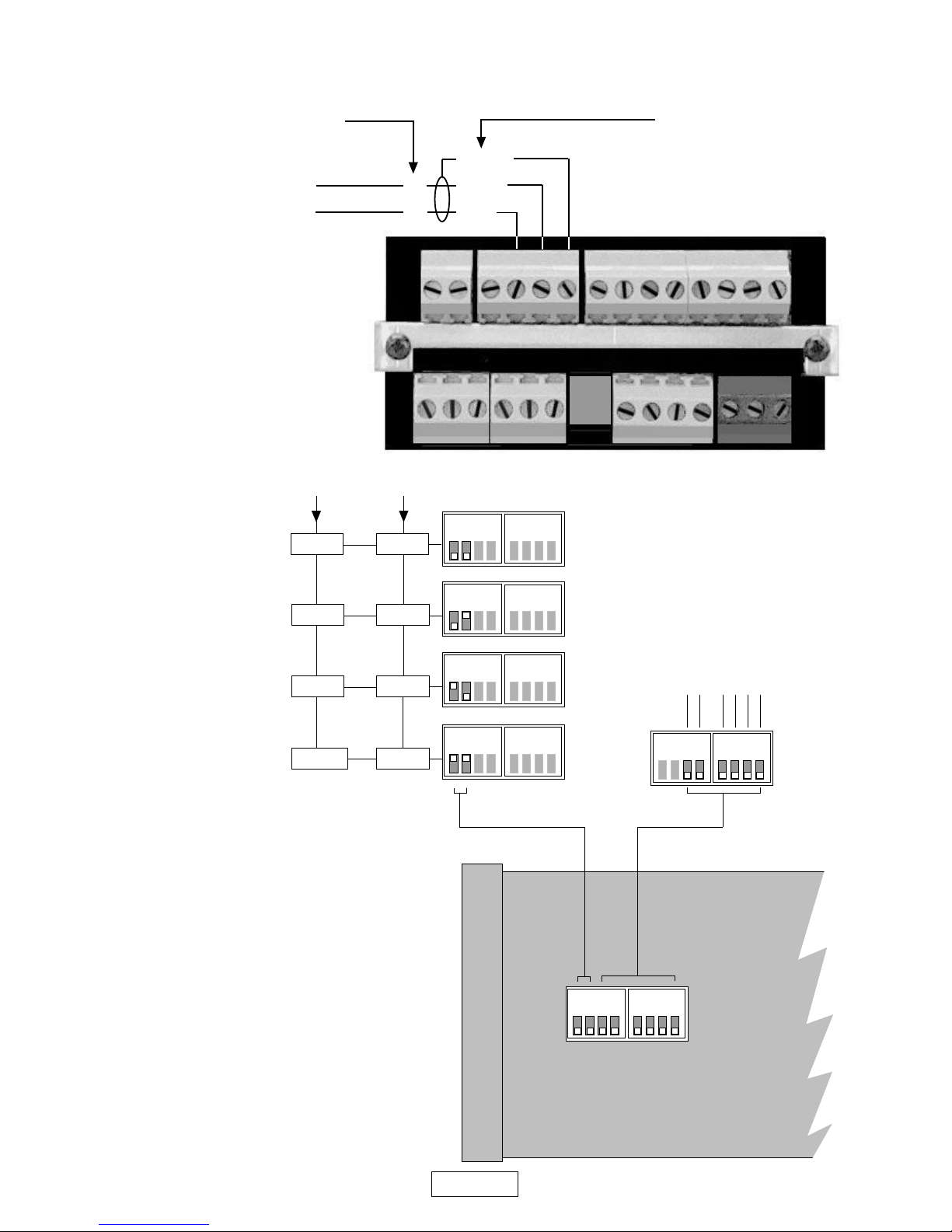
DeviceNet(DN) RS485(485) ModBus RTU(MB) options
1200 125K
4800 250K
9600 500K
19.2K n/a
NO
1 2 3 4
NO
1 2 3 4
NO
1 2 3 4
NO
1 2 3 4
NO
1 2 3 4
NO
1 2 3 4
NO
1 2 3 4
NO
1 2 3 4
NO
1 2 3 4
NO
1 2 3 4
252
4 23222120
1
0
The EDS file for this device is
available from ....
london-electronics.com/lel.eds
Side of meter
Page 20
DeviceNet Notes
Type: Group 2 Slave
Only supports polling
Interscan delay should
be >110mS
NO
1 2 3 4
NO
1 2 3 4
485/modbus
Baudrate
DeviceNet
Baudrate
Shield
White
Blue
A
B
DeviceNet cable IDsRS485/Modbus cable IDs
Data Cable
RS485 ASCII Addressing:
To request a reading , send ...
<STX><Address><r><ETX>
Where Address = 01 to 63
Reply is ...
<STX><ASCII reading><r><ETX>
<r> signifies reading request/reply
NB: No more than 2 requests per
second to any address.
Address
Page 24
Page 21
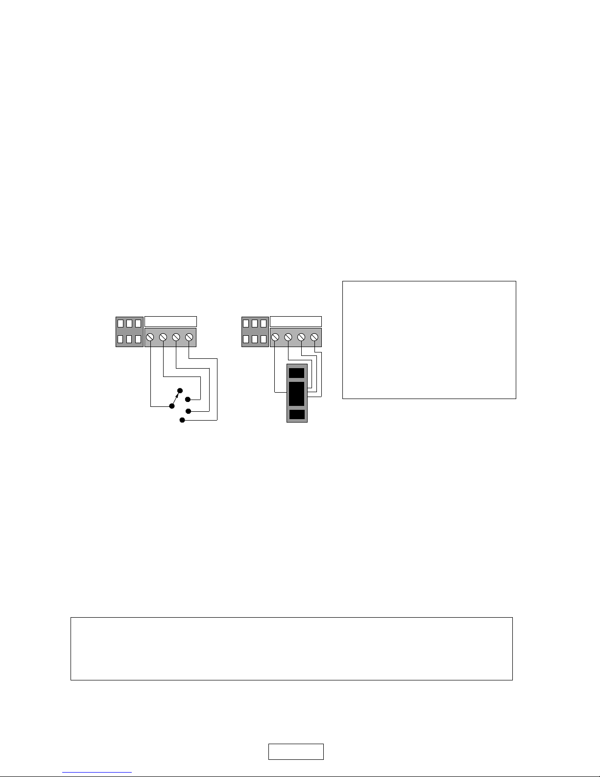
8 Programme Memory Option (description only - separate manual needed)
7 8 9 10
Common
BCD 1
BCD 2
BCD 4
7 8 9 10
Common
BCD 1
BCD 2
BCD 4
6
Simple rotary switch BCD coded switch
* Programming Notes:
Memory location 0 is a ‘GLOBAL’ programming location. When you programme
location 0, with the Mode switch “ON”, the same data will go to all other memory
locations, and their settings will be lost.
Always programme location 0 first if you don’t want to erase and over-write
the data in other locations. Or, if you need less than 8 memories, you can make
sure that location 0 will never be accessed if you connect a link from Common to
BCD1
Useful trick if you
must have 8 memories and need to change the calibration of location 0 ...
If you do want to change memory 0 calibration, switch the Mode switch and the Lock switch “OFF”.
Double check that they are off, then carry out your calibration. Remember to switch both the Mode switch
and the Lock switch “ON”again when you have finished.
All programmes are stored in non-volatile EEPROM memory, which has a typical
storage life of 10 years.
If you want to use a rotary switch
to select up to 8 memory
locations, and to switch up to 8
two-wire signals, switch model
SW2P8W-BCD may be useful.
This is a 1/8DIN unit you can
order separately.
Mode - Always ON*
Alarm Lock
Lock = ON to lock
switch switch
Mode - Always ON*
Alarm Lock
Lock = ON to lock
With this option, you can store up to 8 sets of configuration and calibration data.
This is useful if you want to connect a number of different sensors, each with
different calibration, to the meter, selected by rotary switch. Each memory
location can have its own input/display calibration, alarm settings, and analogue
O/P calibration. NB Linearisation,Theoretical Calibration and InFlight
compensation are not available with this option. Nor is external tare or reset.
Memory locations are addressed using an external switch. If you need up to 4
memories, you may use a simple rotary switch. If you need more than 4 memories
you must use a BCD coded switch, as shown below.....
Page 25

Equipment Specifications
Bezel size 48mm high by 96 mm wide (1/8 DIN)
Panel Cutout 45 mm high by 92 mm wide
Case Depth 125 mm including connectors
Weight 300 grammes
Case Material Black polycarbonate
Connectors Detachable Screw Terminal connectors
Power 95-265 VAC or 11-30 VDC optional
Burden 8VA maximum
Input Signals (bipolar) 4 or 6 wire loadcell up to +/-30mV
Input Resistance >10 Megohms
Accuracy +/-0.05% of range
Span tempco 50ppm/Degree Celsius
Zero Tempco 20ppm/Degree Celsius
Excitation voltage 10VDC +/- 0.1% rated at 120mA
Filtering / smoothing Selectable time constants of 0 to 5 seconds.
A/D conversion Dual slope 10 conversions per second. Resolution 1 in
63000 max. over full range
Display update rate 2 readings per second.
Plug-In Output Options
Analogue O/P 0-10VDC 4-20mA +/-5VDC
Drive capacity >1K Ohms <500 Ohms >1 K Ohms
Isolation 250 VAC Optically isolated
Accuracy +/-0.1% range, +/-10mV for ANV, +/-10uA for ANI
Linearity +/-0.02% of range
Resolution 12 bits
Scaling Fully adjustable, direct or inverse
Alarm Relay O/P 2 or 4 alarms SPST rated 5 Amperes at 250 VAC,
resistive load. Selectable normally open or normally
closed. Selectable energise or de-energise on trip.
Independant hysteresis and inflight compensation on
each alarm relay.
ASCII Data O/P RS232 or RS422 ASCII Value of reading. 1200 baud.
Format 1 start bit, 8 data, no parity. <Measurement><CR>
Isolation 250 VAC optically isolated
Page 22
Page 26

Record of Revisions/Changes
16 April 1999 8 Memory programme facility option added with rev. 2.A software
Front Page - added highlight to indicate availability of MEM-08 option
Table of contents amended to include memory option
Page 4 amended to revise remote connector functions
Page 5 amended to add comment about MEM-08 and Linearisation exclusivity
Page 6 amended to add comment about MEM-08 and Peak/Valley, Tare, reset
exclusivity
Page 9 added to provide general operating guidance for MEM-08
14 June 1999 Version 5.0 Software released. Calibration method amended to include ‘Thoretical’
calibration method
24 Feb. 2000 Ver 5.2 Software released. Auto zero correction changed to allow auto zero only if
reading is within 8 counts of zero. In-flight compensation changed to make 100%
correction for1st pass, 25% correction for all subsequent passes, to provide greater
stability of correction. Re-boot of memory made inaccessible to customers, to
prevent inadvertent loss of setup data. Automatic test routine incorporated to allow
fast factory correction of internal component tolerancing errors during 1st opera
tional QA procedure. Alarm setpoint routine changed to make setting easier. Peak
and Valley display now times-out after 3 seconds. Calibration counter index incor
porated to allow any alteration of calibration parameters to be detected and re
corded without having to enter menu. Line feed character added to end of serial
data string transmission. Filter time constants available 0-5 seconds in 0.5 sec.
increments.
22 March 2000 Ver. 5.3 Software released. Eliminates software bug associated with internal flag
setting.
12 April 2000 Ver. 5.4 Software released. Eliminates software bug associated with alarm setting.
09 March 2001 Modification of Declaration Certificate
11 April 2001 Page 4. Updated switches on rear. From jumpers to DIL switch format.
21 May 2001 Clarifications to manual regarding switches and correction of SP option to AL4
7 June 2001 Ver 5.5 software released to separate filtering and count-by from scaling. Manual re-
written with additional diagrams and explanations
3 October 2001 page 5. Rear Switch changed to indicate ON in lower position (Blue Switch)
page 17. Analogue O/P option board potentiometer positions revised.
11 Nov 2002 Application note added on page 23
14 March 2003 Clarified warnings and intro
21 May 2003 Added more troubleshooting help on page 24
31 July 2003 Declaration of Conformity amended
3 March 2004 Page 19 - changed reference from Grand Intuitive to EasyReader series.
Page 20 - Clarified method of setting meter for MEM08 option
16 March 2004 New Inflight Compensation software released. Changes to alarm setting, lockout
switches, front panel taring control delay, reset function. High alarms now work at or
above the setpoint level - previously only above.
16 June 2004 Added DeviceNet notes to page 20
27 July 2004 Added ModBus RTU and RS485 notes to page 20
15 February 2005 Software upgraded to IP1.2 to correct inverse-scaling bug. Hysteresis on low alarms
set positive instead of negative as previously stated.
28 July 2005 WEEE statement added.
4 November 2005 Added trouble-shooting note to page 26, to show how to clear stored tare values
which may cause the displayed value to jump when the lockout switch is moved to ON
position
20 October 2006 Clarified lockout switch settings on calibration pages.
Page 23
Page 27

Page 24
To get the best possible accuracy and resolution from this meter ...
You’ll need to do a few things for best performance. Loadcell signals can be very small,
compared to noise levels in many industrial environments.
1. Use screened cable for all loadcell connections. Connect the screen to earth
near the meter, not near the loadcell.
2. Make sure any noise can be bypassed to ground before it reaches the meter
To do this, connect either terminal 3 or terminal 7 to ground.
3. If you use the meter’s analogue output, and you want the best accuracy,
ensure that the device which measures the analogue output has a sample
time as long as possible. Fast sampling can degrade noise rejection. If you
can’t increase the sampling time, fit a capacitor across the receiver.
10uF 16V tant. capacitors give dramatic noise improvements on 4-20mA
systems. Screen and earth the analogue output cable at the receiver end only.
This diagram summarises these suggestions....
REAR VIEW
1 2 3 4 5 6 7 8 9 10 11 12 13
14 15 16 17 18 19 20 21 22 23 24 25 26 27
ON
Clean Earth near to the meter
Braid
+
10uF
16V
Tant
+
_
4-20mA I/P
PLC
Clean Earth near PLC
To loadcell
(alternative to pin 3)
Page 28
Page 25
Troubleshooting help.
1. Do you get the signals you expect from your loadcells? An ERROR display means the meter can’t
resolve the input signal.
A basic test is to see whether your loadcells are giving the correct level of output signal. Measure the
signal with an accurate DVM. If you don’t have an accurate DVM, you can use the meter to measure
millivolts. Here’s how...
1. Select Theoretical Calibration with the switch on the back of the meter.
2. Switch the lockout switch OFF
3. Calibrate Zero for InLo = 0 , Dsp Lo = 0
4. Calibrate Span for InHi = 30.000, Dsp Hi = 30.000
5. Set the lockout switch ON
6. Fit a linking wire between terminals 7 and 10 (reset)
7. Press the RESET button on the front of the meter.
The display should now give you a reading in millivolts.
Make a note of the millivolt readings with two known loads applied to you system.
Add these loads to any tare loads, such as platform assemblies, and see whather the results fit with the
data from the loadcell manufacturer.
Here’s an example ...
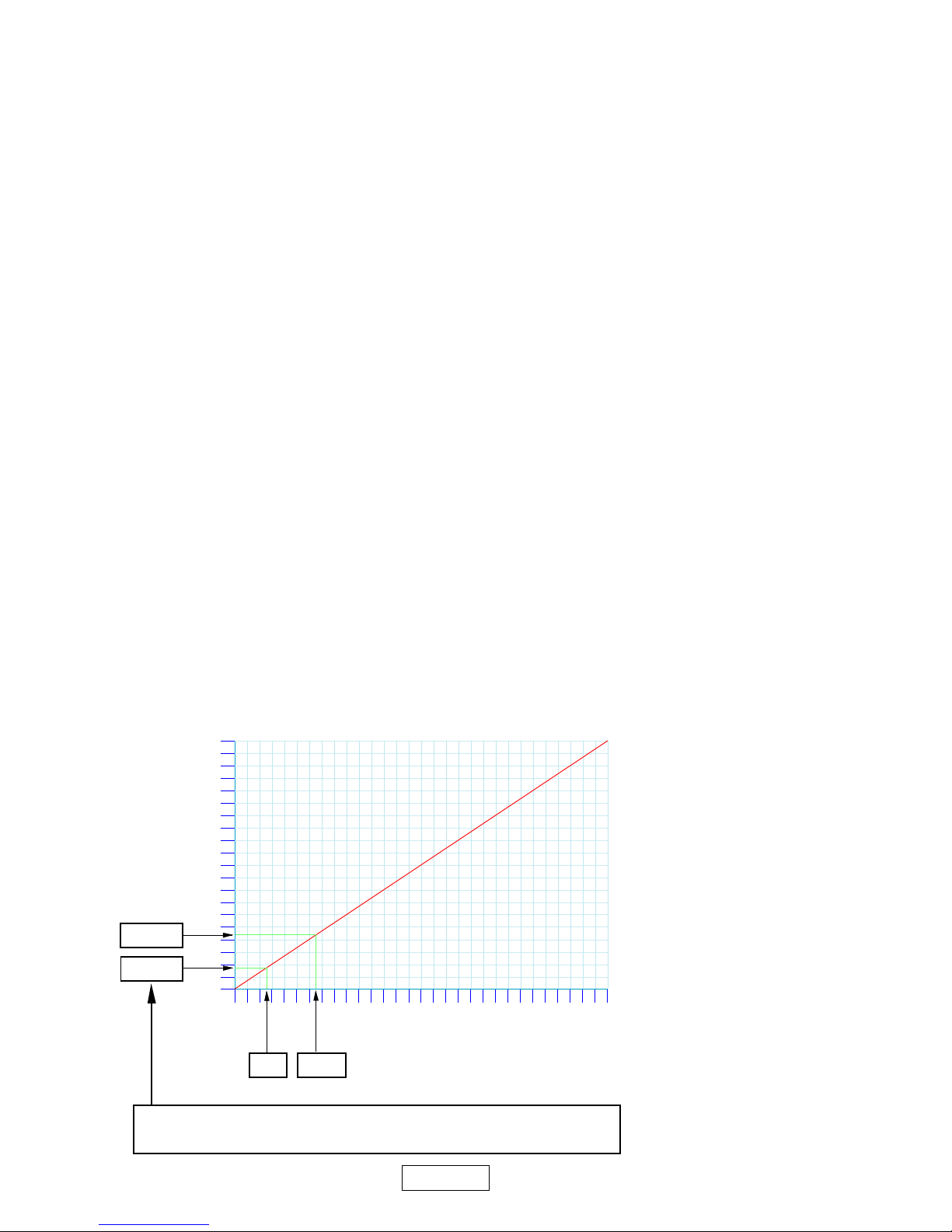
You measure the millivolt signals with 0kg and 400kg on your platform.
The platform, which rests on the loadcells, weighs 250 kg.
Your platform uses 3 loadcells, each rated 1000kg. Sensitivity 2mV per volt.
Our excitation is 10V DC, so for 0-3000 kg we expect to see a signal of 0-20mV
This can be shown on a graph as follows:-
20
19
18
17
16
15
14
13
12
11
10
9
8
7
6
5
4
3
2
1
0
0
100
200
300
400
500
600
700
800
900
1000
1100
1200
1300
1400
1500
1600
1700
1800
1900
2000
2100
2200
2300
2400
2500
2600
2700
2800
2900
3000
mV
Kilograms
1.75mV
4.37mV
0Kg 400kg
Do you get these signals for 0Kg and 400kg? If not, you’ll need to find
out why. Is the excitation voltage REALLY 10V?
Page 29
Page 26
Troubleshooting help - continued
2. The display value changes when you switch the lockout ON.
This is normal, and can be eliminated. Here is what’s happening ....
At some time in the past, you have tared the display. The tare value is saved in memory.
When you have the lockout switch OFF, the display will always be GROSS, in other words the tare
value will be ignored.
When you have the lockout switch ON, the tare value will be subtracted from the gorss value and the
display will be NETT value.
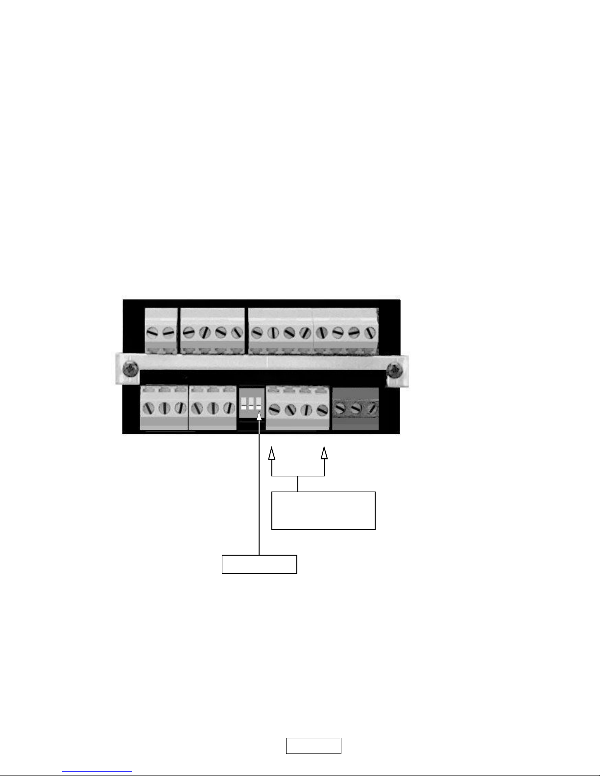
To clear the tare value to 0, simply reset the meter, when the lockout switch is ON, see below...
This will not affect your calibration.
REAR VIEW
1 2 3 4 5 6 7 8 9 10 11 12 13
ON
1. Switch 3 = ON
2. Briefly link terminal 7
to terminal 10 to reset
the Tare memory to 0
Page 30

Page 27
Page 31

Page 28
Waste Electrical and Electronic Equipment (WEEE)
In Europe, this equipment must be disposed of in accordance with European
Parliamentary Directive 2002/96/EC
This directive encourages recycling and the reduction of waste materials in the
environment.
This means it must be sent to an approved recycling plant if you want to dispose of it.
It must not be thrown away in general rubbish.
If you are unable to dispose of this item locally, you may send it to us for recycling.
Conditions:
1. We will only accept items of our manufacture.
2. You must pay for the transport of the goods to us.
3. We will only accept items if they include a signed declaration by an authorised
person in your organisation, stating that :-
i. The item is safe to handle and has no contaminants which may be
harmful to health.
ii. You wish us to dispose of or destroy the item(s)
Page 32

Page 29
Declaration of Conformity
Conditions
The meters are permitted a worst case error of 1% of A/D range during electro-magnetic disturbance,
and must recover automatically when disturbance ceases without the need for human intervention, such as
resetting, power-down etc.
The meters covered by this certificate must be installed in adherence to the following conditions :-
Signal cabling shall be routed separately to power carrying cabling (includes relay output wiring)
All signal cabling shall be screened. The screen shall only be terminated to the power earth terminal
This is to confirm that the Product covered by this declaration have been designed and manufactured to
meet the limits of the following EMC Standard :
EN61326-1:1997
and has been designed to meet the applicable sections of the following safety standards
EN61010-1:2001
Declaration Reference : INTUITIVE
Issue Date : 9 October 1998 revised 31 July 2003
Products Covered : INTUITIVE series
Title : DOC-INTUITIVE
Declared as true and correct, for and on behalf of London Electronics Ltd.
J.R.Lees Director
 Loading...