

Page 1
1
Document Ref:pm65\manuals\INT2_P Revision:19 Dated: 28 February 2011
Software version F00.21
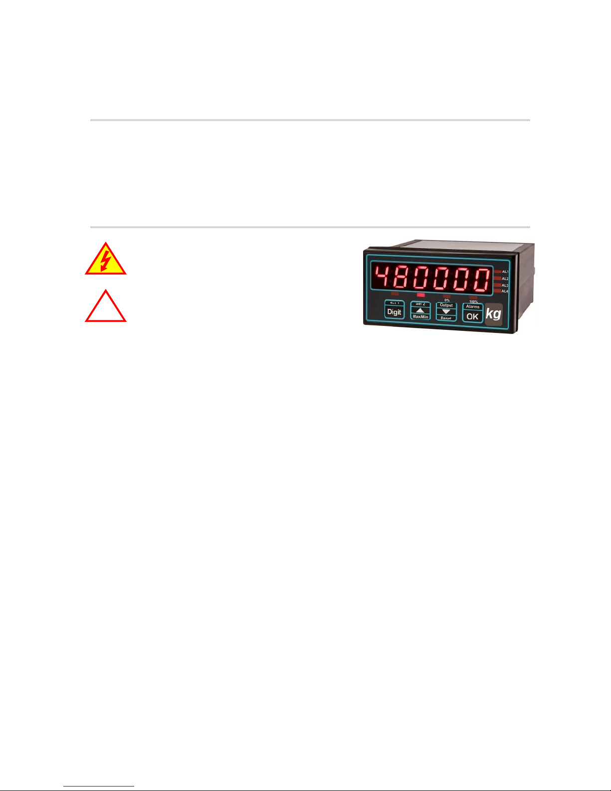
Panel mounting process indicator
IL2-P
Connection details, scaling and general information
!
Caution: There is a risk of electrical
shock if this instrument is not properly installed
Caution: Risk of danger: Read the whole
manual before you install this meter
London Electronics Limited
Thorncote Road, Near Sandy, Bedfordshire SG19 1PU
Tel +44(0)1767 626444 Fax +44(0)1767 626446
www.london-electronics.com [email protected]
Page 2

2
.
Warranty
We warrant our products against defects in materials or workmanship for a period of three
(3) years from the date of purchase.
In the event of a defect during the warranty period, the unit should be returned, freight (and
all duties and taxes) prepaid by the Buyer to the authorised distributor from where the unit
was purchased.
The Distributor, at its option, will repair or replace the defective unit. The unit
will be returned to the Buyer with freight charges prepaid by the distributor.
LIMITATION OF WARRANTY
The foregoing warranty shall not apply to defects resulting from:
1. Improper or inadequate maintenance by the buyer.
2. Unauthorised modification or misuse.
3. Operation outside the environmental specification of the product.
4. Mishandling or abuse.
The warranty set forth above is exclusive and no other warranty, whether written or oral is
expressed or implied. We specifically disclaim the implied warranties of merchantability
and fitness for a particular purpose.
EXCLUSIVE REMEDIES
The remedies provided herein are the buyer’s sole and exclusive remedies.
In no event shall we be liable for direct, indirect, incidental or consequential damages
(including loss of profits) whether based on contract, tort or any other legal theory.
Page 3

3
Warranty 2
Warnings 4
Introduction 5
General Description 6
Panel mounting & Installation - Class II 7
DIN Rail mounting option 8
Other Mounting options 9
Wiring Advice 10
Connections 11
Installation hints for best performance 12-13
Easy/Advanced menu mode 14
Language Selection 15
Display Brightness 16
Display Calibration Modes 17
Direct Calibration 18-19
Theoretical Calibration 20-21
Sensor Drift correction 22
Logic Input connections & Front Buttons 23
Factory defaults 24
Calibration Audit number 24
Signal Filtering / Averaging 25
Last Digit rounding 26
Menu Timeout adjustment 27
Bootup Routine choices 28
Error Codes 29
WEEE 30
Equipment Specifications 31
Record of Revisions 32
Notes 33-25
Declaration of Conformity 36
* Need a manual urgently?
You can download manuals from our website
Contents
Page 4
4
Safety First ..............Don't assume anything............. Always double check.
If in doubt, ask someone who is QUALIFIED to assist you in the subject.
Warnings
Please carefully read this manual and all warnings. Install the meter ONLY when you are sure
that you’ve covered all aspects.
Where the product is intended for “UL” installations, removal or
addition of option boards is not permitted.
Check that the model number and supply voltage suit your application before
you install the meter.
Connect the meter according to current IEE regulations, IEC61010 &
NFPA:70 National Electric Code in USA.
This meter is for Installation class II service only. This means it
has exposed electrical and power terminals. You must install it in a
suitable fire enclosure which will also protect users from electric shock
We designed this meter for Pollution-Degree 2 environments only.
Power supplies to this equipment must have anti-surge (T) fuses rated at 400mA for
230V supply, 400mA for 110V supply or 2A for DC supplies in the range 11-30VDC.
Only Siba fuses in series 189500, cULus listed according to file #E167295 are
accepted for this service under the terms of UL listing. A switch or circuit breaker, clearly
marked as a disconnecting device, must be included close to the installation.
Don’t touch any circuitry after you have connected the meter, because there may be
lethal voltages on the circuit board.
Only adjust on-board switches or connections with the power turned off
Make sure all screw terminals are tight before you switch the meter on.
Only clean the meter’s front with a soft damp cloth. Only lightly dampen with water.
Do not use any other solvents. The behind-panel case may be cleaned with a dry cloth
only, use no liquid or solvent on it.
!
!
!
!
!
!
Page 5

5
Introduction
Please contact us if you need help, if you have a complaint, or if you have suggestions to help
us improve our products or services.
If you contact us about a product you already have, please tell us the full model number and
serial number, so that we can give you accurate and fast help.
This product has a 3 year warranty. We will put right or replace any meter which is faulty
because of bad workmanship or materials. This warranty does not cover damage caused by
misuse or accident.
If you return a unit for repair, please include a detailed description of the problem, and the
name of a contact who we can refer to for any questions. Please mark for the attention of the
QA Department.
IMPORTANT
If this equipment is important to your process, you may want to buy a spare to cover possible
failure or accidental damage in the future.
This is because during factory shutdown periods, you may have to to wait several weeks for
an equivalent replacement, or we may have no stock at the time you urgently need it.
You may also need to pay extra carriage charges if you want a fast, guaranteed courier service.
Warranty repairs or replacements are usually returned with a standard courier service.
We do not offer compensation for losses caused by failure of this instrument.
If you do not agree with these conditions, please return this item in unused, condition, in its
original packaging and we will refund the purchase price, excluding any carriage paid.
We thought you’d prefer to know about possible delays and extra charges now, rather than
during a panic. A spare unit could help to avoid these issues.
We always try to improve our products and services, so these may change over time. You
should keep this manual safely, because future manuals, for new designs, may not describe
this product accurately.
We believe these instructions are accurate, and that we have competently designed and
manufactured the product, but please let us know if you find any errors.
Page 6

6
General Description
This series of meters accepts industrial sensors to allow various physical measurements to
be made, such a weight, temperature, pressure, humidity etc. Different models are available
for different sensor types.
The main function of this series is to give a numeric readout of the variable being monitored.
Most models include an excitation power output, to power the sensor directly.
Various optional output modules are also available on the more advanced versions, to give
alarm relay outputs, analogue output or digital communications, or any combination of these
options.
Meters are programmed using front panel pushbuttons. The buttons may be locked with a
rear switch.
Meters have two power supply options : 100-240 VAC or 11-30VDC
These meters are designed to mount into a protective enclosure which will protect users from
contact with power and signal wiring.
These units must be installed fully assembled, and must be installed according to local electrical
installation rules. When properly installed, they provide ingress protection to IP65 / NMA4X
from the front
Safety
Obey all safety warnings in this manual, and install the meter according to local wiring and
installation regulations. Failure to follow these guidelines may cause damage to the meter,
connected equipment, or may be harmful to personnel.
Any moving mechanical device controlled by this equipment must have suitable access guards
to prevent injury to personnel if the meter should fail.
!
Caution: There is a risk of electrical
shock if this instrument is not properly installed
Caution: Risk of danger: Read the whole
manual before you install this meter
Page 7
7
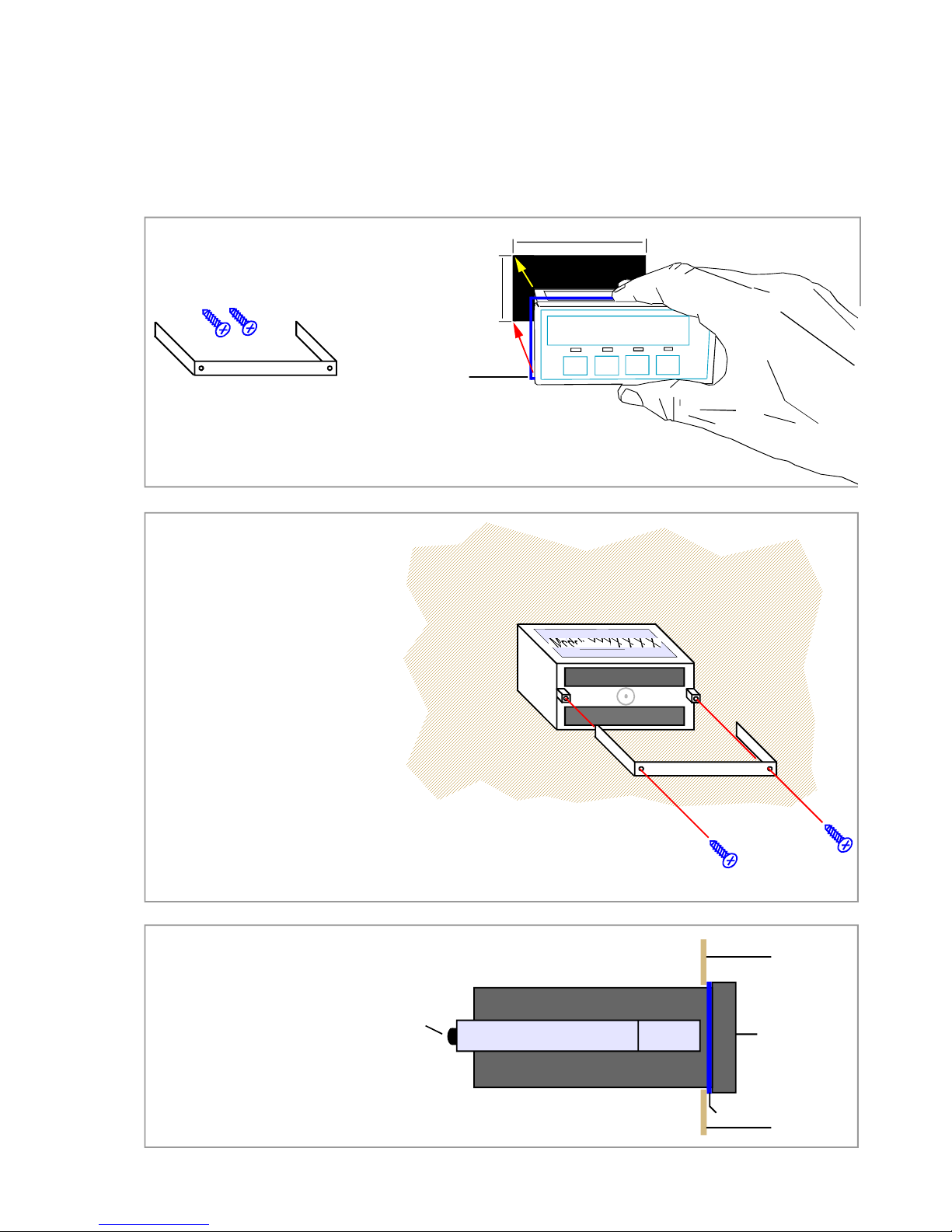
Panel Mounting and Installation - Class II
Install the meters in a suitable protective electrical control enclosure according to local wiring
regulations. See specifications for maximum allowable temperature in enclosure. Allow
adequate air circulation.
888888
92mm +1mm -0mm
45mm +1mm -0mm
Panel cutout
Installing into front of panel
Remove the two rear bracket
screws and safely store them
and the U-Bracket for later fitting.
Gasket
Gasket
Front surface
of enclosure
Front surface
of enclosure
Front surface
of meter
U-Bracket
Bracket screw (1 of 2)
Left side of meter case
U-Bracket
Bracket screws
U-Bracket
Bracket screws
Slide the meter, with gasket
into the panel cutout
Securing into the panel
Re-fit the U-Bracket and tighten the bracket
screws to firmly clamp the meter in place.
Check that the gasket is evenly pinched
between the meter’s front bezel and the
enclosure front
Ventilation
There should be sufficient ventilation in the
enclosure to ensure that the meter’s case is
always kept to less than 60C.
Meter Spacing.
Meters should be spaced apart sufficiently
to allow a free flow of ventilation air around
the meters, such that no part of the case will
exceed 60C
Side view of meter installed in panel
Page 8
8
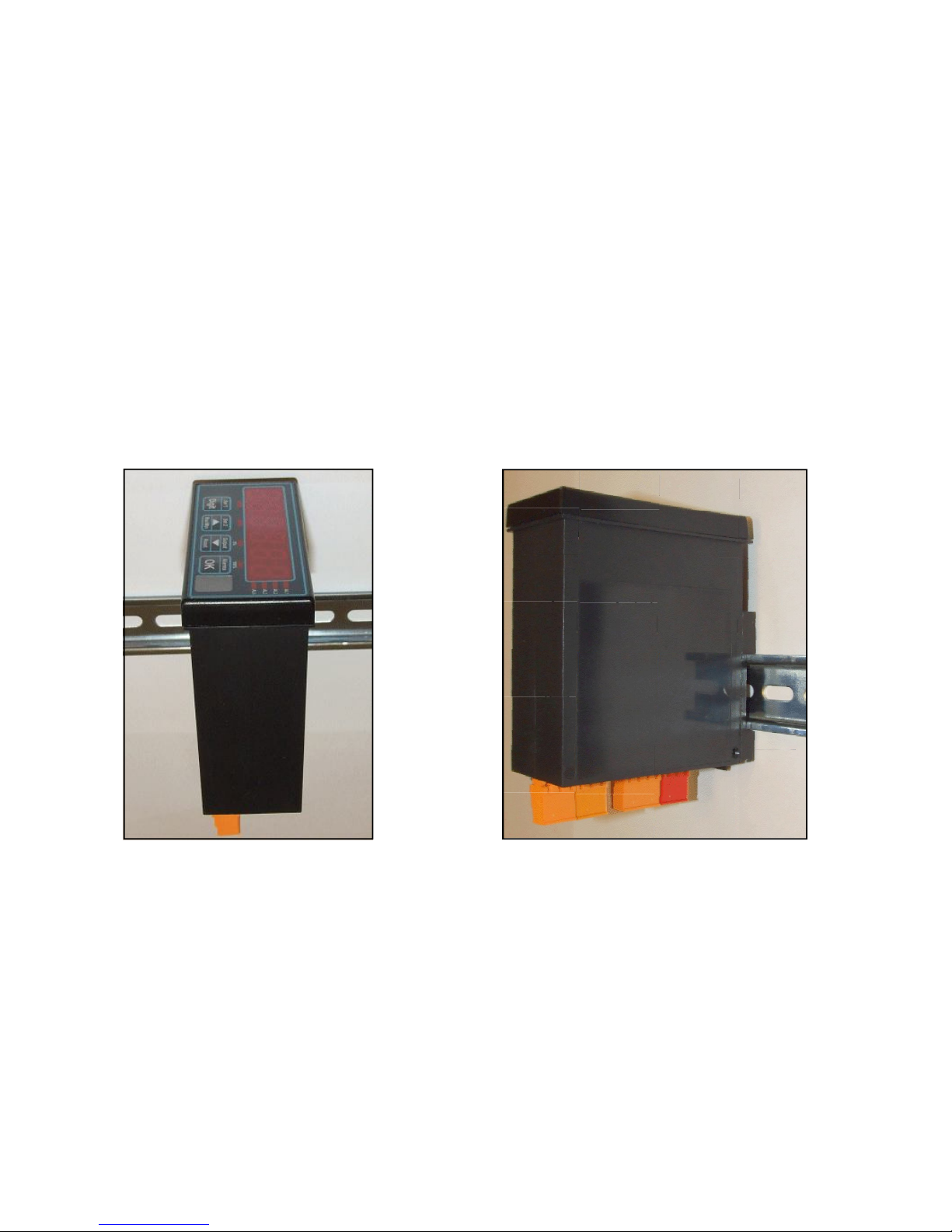
DIN Rail Mounting option
This series is ideal if you need high precision signal monitoring. Sometimes, there is not
enough spare area available to have front panel indication, so in such cases, we offer a DIN
rail mounting option, which allows the meter to be installed within a control panel.
Detachable connectors add to the simplicity of installation, and of course the setup method is
identical to the panel mounting version, so you don’t need to learn a new method.
The display remains active, so you can see at a glance the status of your signals, and
programming is simple, using the 4 buttons.
Install the meters in a suitable protective electrical control enclosure according to local wiring
regulations. See specifications for maximum allowable temperature in enclosure. Allow
adequate air circulation.
Securing into the panel
Use standard top-Hat DIN rail 35 mm x 7.5 mm (EN 50022, BS 5584, DIN 46277-3)
Ventilation
There should be sufficient ventilation in the enclosure to ensure that the meter’s case is
always kept to less than 60C.
Meter Spacing.
Meters should be spaced apart sufficiently to allow a free flow of ventilation air around the
meters, such that no part of the case will exceed 60C
Page 9
9
Other mounting options
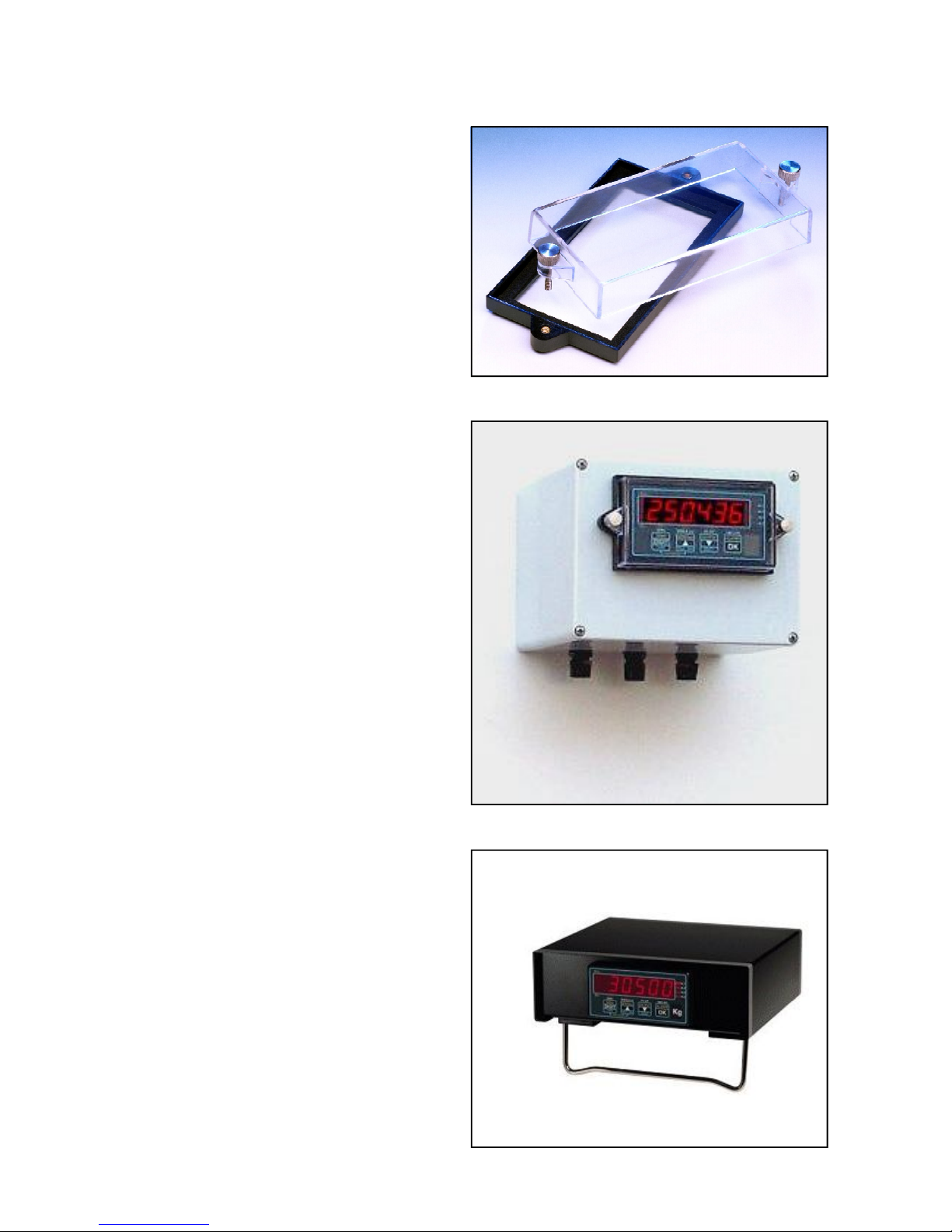
IP67 SPC4
The SPC4 splashproof cover gives
IP67 / NEMA4-X protection for the
front of your meter. Ideal for use in
harsh wet environments.
Available with optional security tag
ports to allow you to fit your own
crimped wire tamper-seals, to prevent or indicate unauthorised access
(Similar to tags used on electricity
meters)
Wall Box
The Wallbox is sealed IP65 all round,
and is supplied with the meter installed, for you to wire to, via 3 cable
glands. It comes complete with SPC4
splashproof cover.
We also offer a dual version of this
enclosure, which can take 2 meters,
one above the other.
PCC Series
The PCC series of Portable Carrying
cases is ideal for housing your panel
meters so that they can be used in the
lab. These enclosure come fully
wired, with panel meters fitted and
with IEC switched power connector
plus any input or output connectors,
as required.
Versions are available to accept 1, 2,
4, 6, 8, 12 or 16 meters
Page 10
10
Wiring Advice
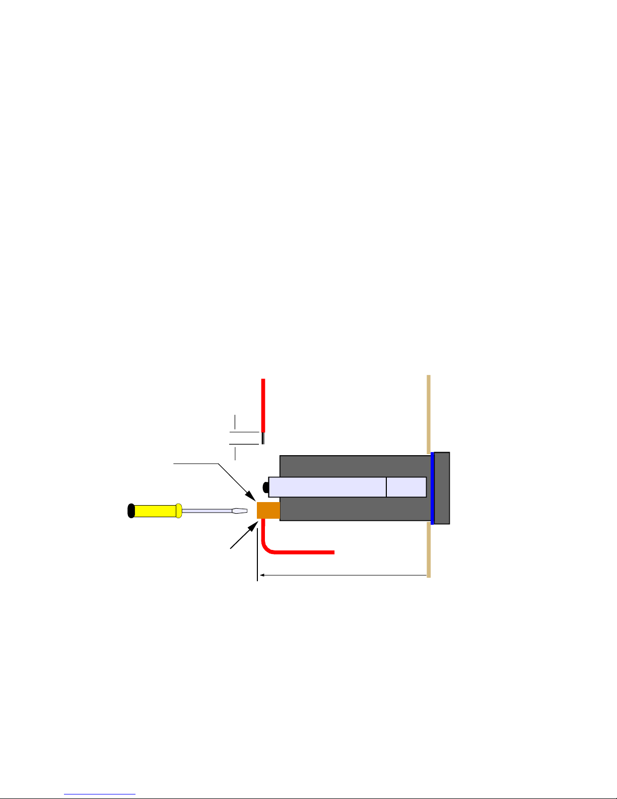
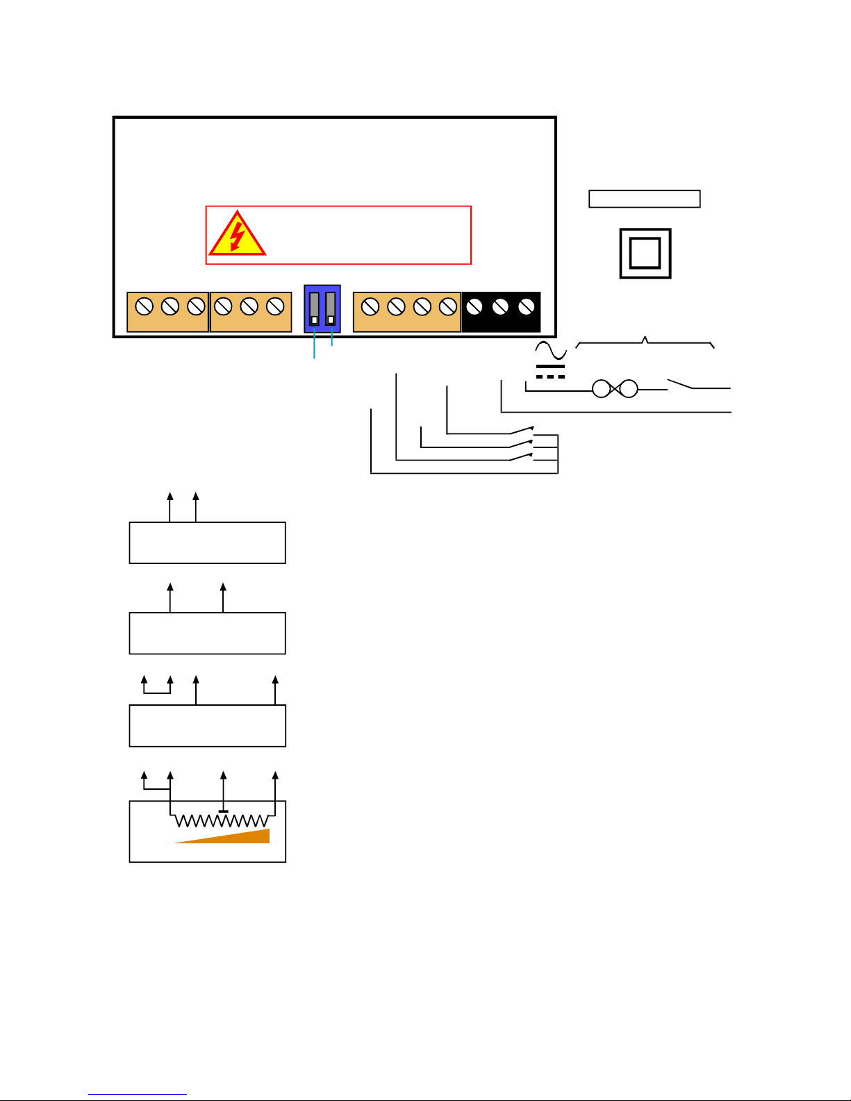
This meter uses detachable screw terminal connectors. Refer to the wiring diagram on the
following page for the correct positioning of each wire.
The conductors you use must be suitable for the meter’s temperature, current and voltage
rating, which is broadly described as follows:-
Cable Temperature Rating
All cables must be rated for operation up to 90C continuous.
Cable gauge and screw tightness
The connectors on this instrument can accept conductors up to 16 gauge AWG / 1.5mm
2
c.s.a. The minimum cross sectional area shall be 22 gauge AWG / 0.5mm2 . Tighten screw
terminals to 7.0 lb/in torque / 0.8 Nm torque.
Cable insulation voltage rating
Cables shall have an insulation voltage rating of at least 380V continuous.
Wire preparation:
We recommend multi-strand wire, because it withstands vibration better than single strand
cable. Pull the wire firmly after you make the connection to confirm it is tight.
Use screened cable for all signal and control wiring and connect the screen to earth at the
destination end only. Route signal cabling away from power cabling and relay switching
cabling, to avoid electrical noise interference.
U-Bracket
No bare wires exposed
Terminal screwdiver - 3mm blade
Strip back
5mm max.
Outside
enc lo sure
Insid e
enc lo sure
Side view of meter
Detachable
connectors
125mm behind panel
Page 11
11
Connections
Alarm Lock
Calib’n Lock
Common
Tare
Peak/Valley
Reset
Logic Inputs Power
Signal I/P & Excitation
Excitation -
Signal -
mA +
V +
no connection
Excitation +
N L
- +
Remote
contacts
(5V DC 1mA)
Warning:
Disconnect all power before
exposing the rear of the meter
Class II Installation
Not used
Fuse Switch
Circuit breaker
Power
Customer-supplied disconnection
and overload protection devices
1 2 3 4 5 6 7 8 9 10 11 12 13
4-20 mA
Active source
+
2 3
0-10V
Active source
+
2 4
4-20 mA 2 wire
passive source
1 2 3 6
+
3 wire potentiometer
1 2 4 6
+
Only possible if you have -POT
option installed, which provides
10V regulated excitation output.
Note that terminals 1 and 2
must be linked.
EXAM PLES
Page 12
12
Installation hints for best performance
This section offers several suggestions which will help you get the best performance from
your measurement system.
Some sensors generate comparitively small signals which can easily be corrupted by the
potentially high level of electrical noise which can be created by electrical machinery such as
motors, welding systems, discharge lighting, AC power inverters and solenoids. These steps
will ensure you get the best possible performance from your system.
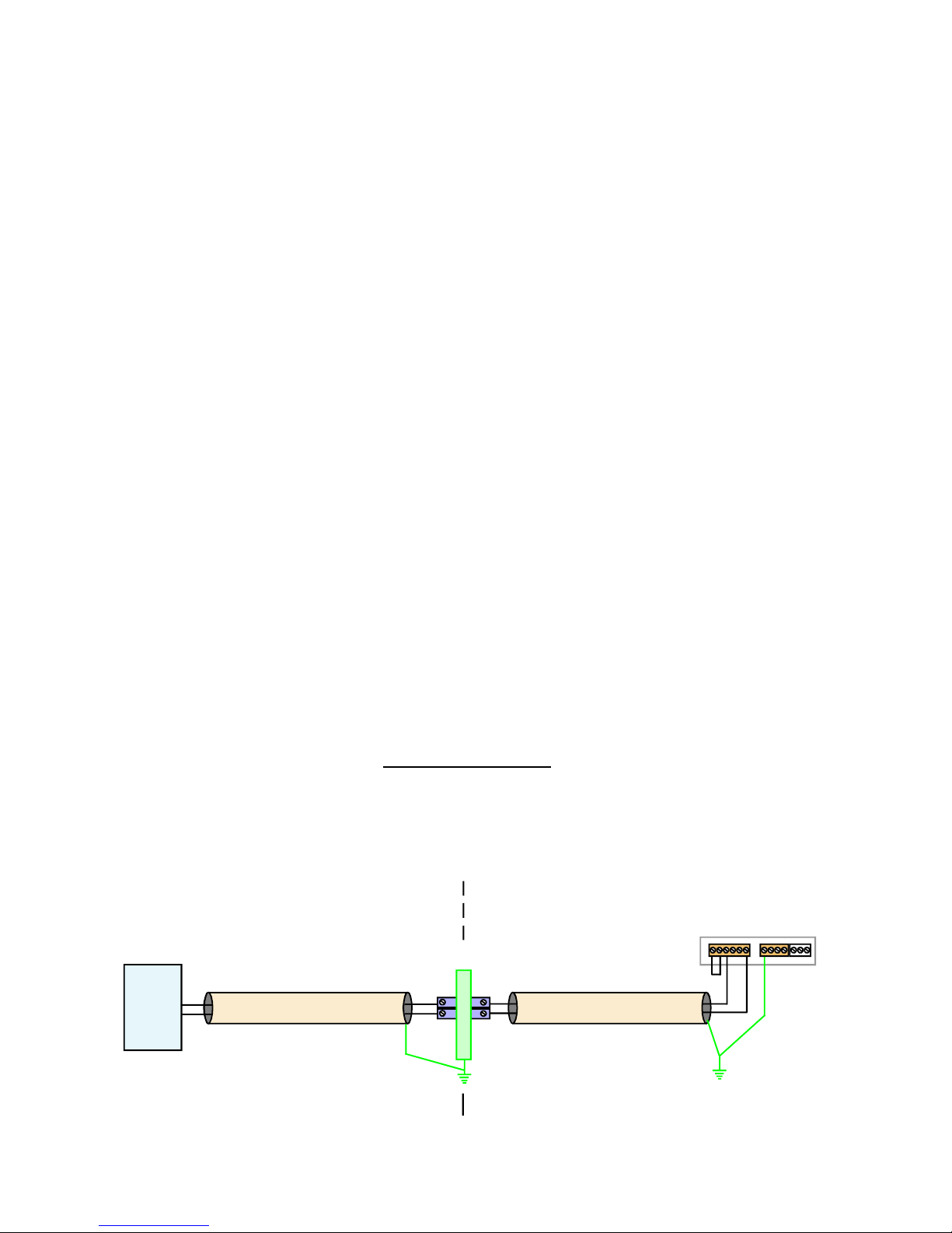
1. Use good quality screened signal cable, with twisted pairs. Belden 8777NH,
Belden 9503 and AlphaWire 6010C are good choices, available from many
electrical distributors.
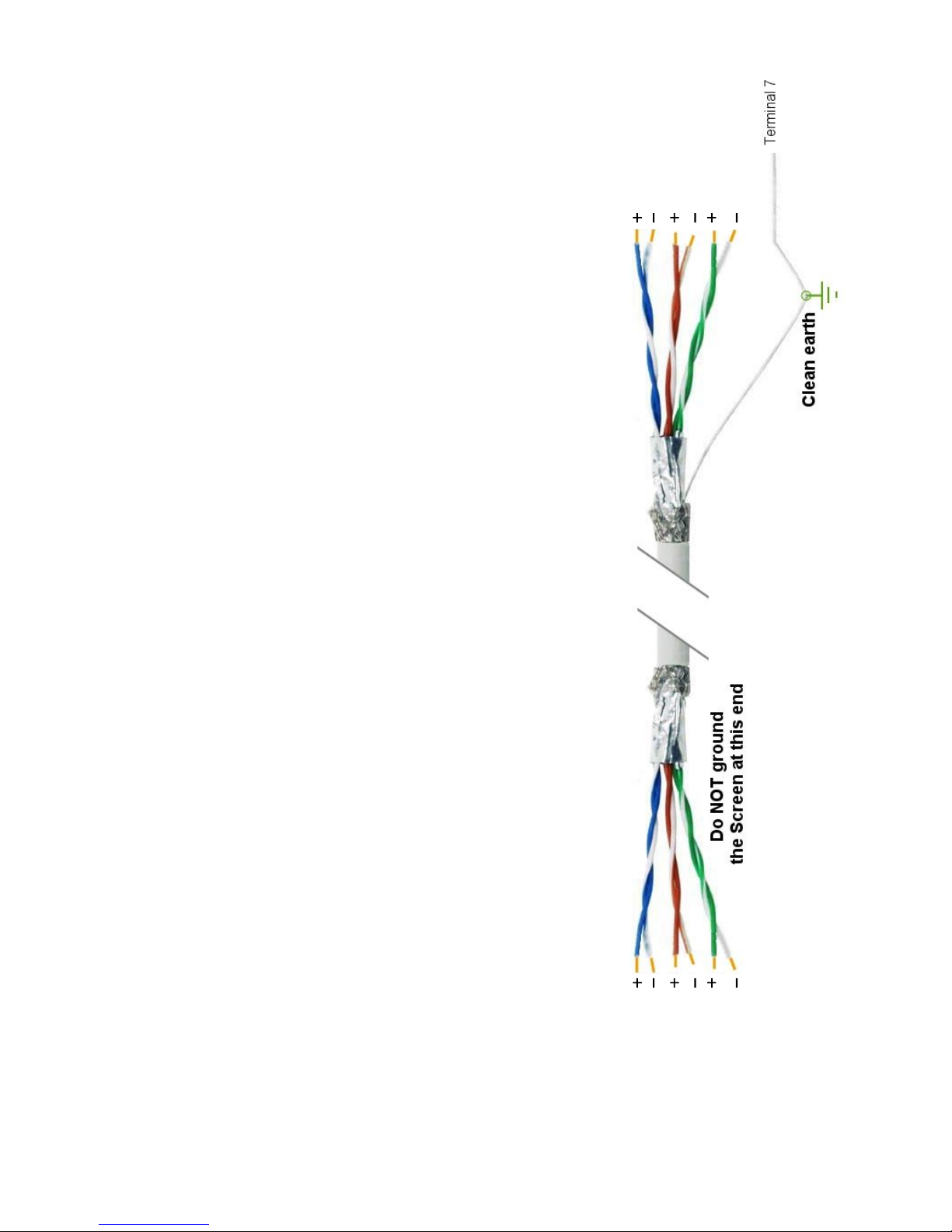
2. If you are using multi-pair twisted cable, each pair should be dedicated to a single
display as shown opposite, for maximum noise immunity.This will ensure that any
electrical noise induced in the cable is properly cancelled. Mixing destinations
carelessly amongst the twisted pairs can actually worsen noise performance.
3. The cable should be routed away from noisy wiring and devices such as power
feeds from inverters, discharge-lighting cables, welder cabling etc, and should
preferrably be routed in a dedicated low voltage signalling/instrumentation conduit
or cable tray.
4. Screened cable should be earthed at the display end only.
5. All wires and screens coming out of the screened cable should be kept as short
as possible to minimise pickup of noise.
6. If you are using barriers, you should earth your screen as shown below, paying
particular care that you do not earth both ends of any run of of cable.
Barriers
EARTH
Connect screen
to earth ONLY
at this end.
Connect screen
to earth ONLY
at this end.
Do not
connect
screen at
this end.
Do not
connect
screen at
this end.
Length of screened cable
Length of screened cable
Sensor
Hazardous Area Safe Area
Terminal 7
on logic
input
connector
Clean Earth
Signal Input
Logic Input
Power Input
Display connections
Sensor connections
Barrier connections
Page 13
13
Display 1
Display 2
Display 3
Sensor 1
Sensor 2
Sensor 3
When using multi-core screened cable to connect several displays to several sensors, please be sure to use one twisted pair for
each display and sensor.
Do NOT use a wire from one pair for signal positive and a wire from another pair for signal negative, as this will prevent the
twisted cables form cancelling any induced electrical noise.
Displays
Sensors
Page 14

14
Easy or Advanced menu mode
You can choose from two menu modes.
1. Easy Mode - This limits the menu to the most commonly required features, in order
to make it less complex and easier to navigate. This is the default level.
2. Advanced Mode - This gives you access to all available menu features.
Each menu feature in this manual has a heading note to tell you whether it
is available in Easy or Advanced mode.
How to choose menu mode:-
!
!
Set1
Set2 Output
Alarms
Digit
OK
Max/Min
Reset
Lockout Switch must be OFF
Press together briefly
Set1
Set2 Output
Alarms
Digit
OK
Max/Min
Reset
Press briefly
Set1 Set2 Output Alarms
Digit
OK
Max/Min Reset
Press to toggle
Set1
Set2 Output
Alarms
Digit
OK
Max/Min
Reset
Press to accept
1
2
3
4
Done!
Each press of the DOWN
arrow, or UP arrow will
alternate between showing
Adv. or EASy
This feature is available in Easy and Advanced Modes
OFF
Circuit board ON
Press OK a few times, until you
see Adv. or EASy
Press OK to select your choice.
Page 15
15
Set1
Set2 Output
Alarms
Digit
OK
Max/Min
Reset
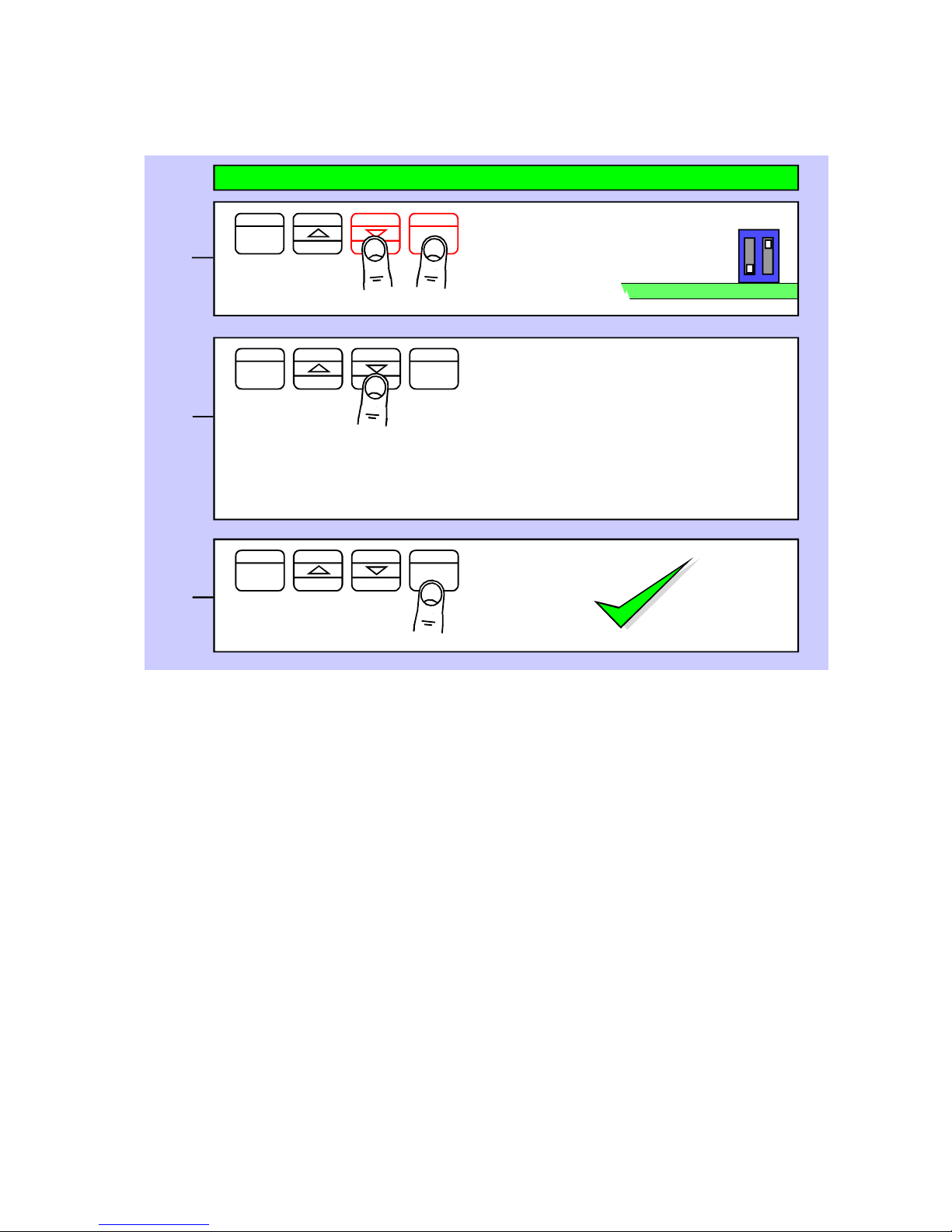
Language Selection for user interface
You can select English or French menu prompts.
Lockout Switch must be OFF
Press together, briefly
Set1
Set2 Output
Alarms
Digit
OK
Max/Min
Reset
Display shows
UI Eng (Default)
for User Interface English
or
UI FrA
for User Interface French
1
2
3
Set1
Set2 Output
Alarms
Digit
OK
Max/Min
Reset
Done!
This feature is available in Easy and Advanced Modes
Press to toggle
Press to accept
OFF
Circuit board ON
Page 16
16
Set1 Set2 Output Alarms
Digit
OK
Max/Min
Reset
Display Brightness
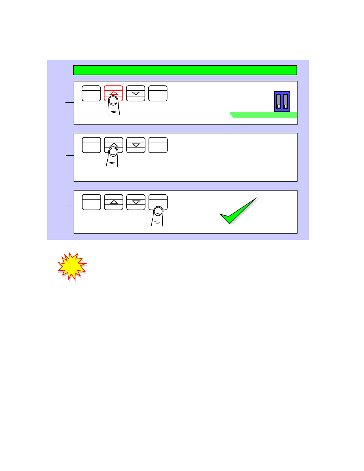
You can adjust the display brightness at any time, provided the display is locked.
Lockout Switch must be ON
Press 3 seconds
Set1 Set2 Output Alarms
Digit
OK
Max/Min
Reset
Press for 3 seconds
Display shows bright
Each press of the UP button will select a
new brightness level.There are 7
brightness levels to choose from.
(Default = Full brightness)
Set1
Set2 Output
Alarms
Digit
OK
Max/Min
Reset
Press to accept
1
2
3
Done!
!
!
Did you know, we make this display in two brightness versions?
Standard brightness for use inside, and Daylight Viewing for use outside
in direct sunlight. The Daylight Viewing version has suffix -DLV in its part
number.
This feature is available in Easy and Advanced Modes
OFF
Circuit board ON
Page 17
17
Set1
Set2 Output
Alarms
Digit
OK
Max/Min
Reset
Meter Calibration Modes
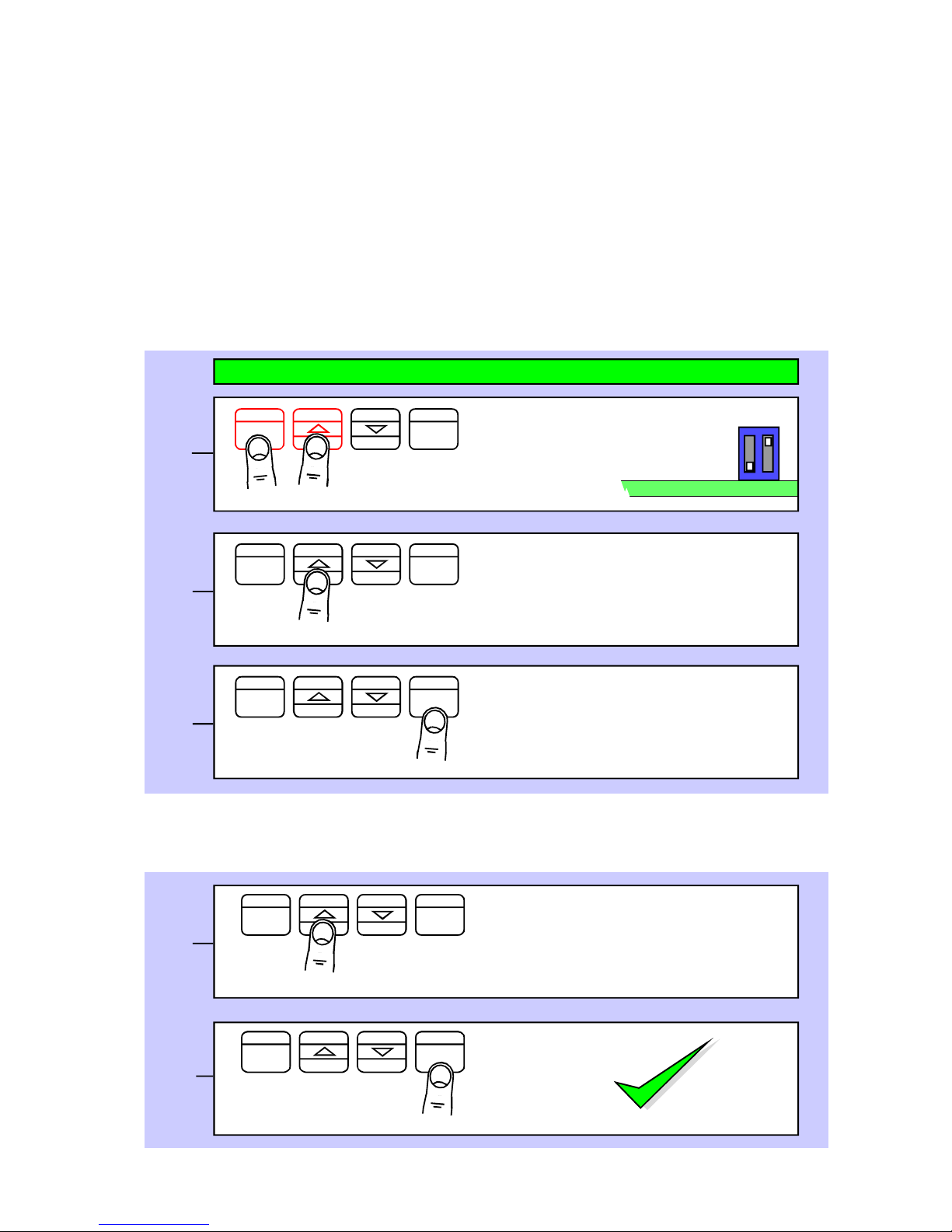
You can choose from two main calibration methods.
1. Direct Calibration - this is when you connect the meter to your system and
make the meter read what you want it to, at 2 different points. This is the preferred
calibration method, because it allows you to calibrate the system as a whole.
2. Theoretical Calibration - this is when you type in the sensor’s theoretical
signal level at the bottom and top of itsrange and then type in the value the
display should show, for each signal level.
How to choose a calibration method:-
Lockout Switch must be OFF
Press 3 seconds
Set1
Set2 Output
Alarms
Digit
OK
Max/Min
Reset
Press to select dirECt or thEor
Display shows CAL Src then
dI re Ct
or
thEor (Default)
Set1
Set2 Output
Alarms
Digit
OK
Max/Min Reset
Press to accept
If you chose Theoretical, you will now be asked whether your input signal
will be DC Current or DC voltage ... the display will show Input followed
by dC A or dC V
Set1 Set2 Output Alarms
Digit
OK
Max/Min
Reset
Press to select dc A or dc V
Display shows Input then
dC A for current or
dC V for voltage (Default)
Set1
Set2 Output
Alarms
Digit
OK
Max/Min
Reset
Press to accept
1
2
3
4
5
Done!
This feature is available in Easy and Advanced Modes
OFF
Circuit board ON
Page 18
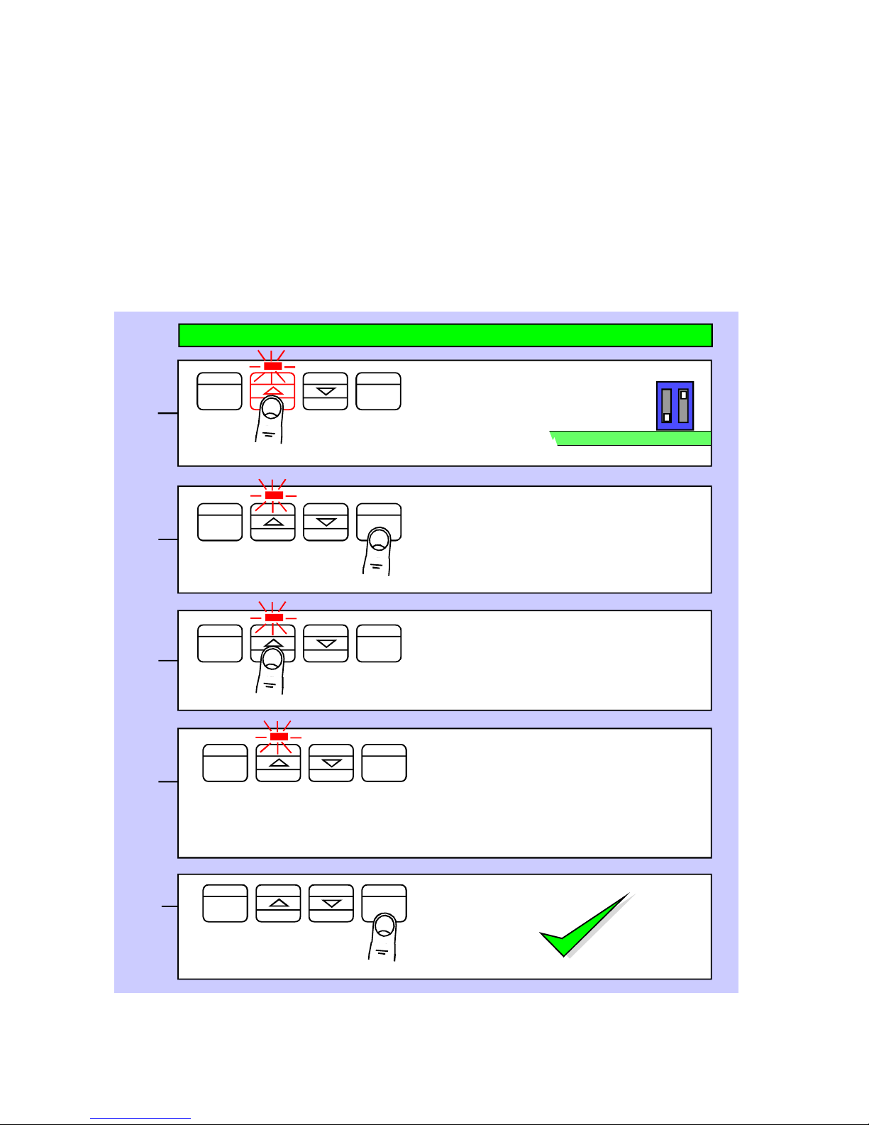
18
Set1 Set2 Output Alarms
Digit
OK
Max/Min
Reset
Direct Calibration - Full Scale Setting
This is when you connect the meter to your system and make the meter read what
you want it to, at 2 different points. This is the preferred calibration method, because
it allows you to calibrate the system as a whole.
How to do direct calibration:-
If you have not done so before, please select Direct Calibration mode from
the previous page.
First we recommend you set the FULL SCALE calibration ...
Lockout Switch must be OFF
Display shows direCt followed
by SEt Hi
Press 3 seconds
Set1
Set2 Output
Alarms
Digit
OK
Max/Min Reset
Apply the highest calibration signal you
can achieve, ideally 100% of system
capacity. You can use less, but you will
get better accuracy with higher signals.
Now press OK
Set1 Set2 Output Alarms
Digit
OK
Max/Min Reset
Press for 3 seconds
Set1
Set2 Output
Alarms
Digit
OK
Max/Min Reset
You can now set the display value you
want to see - use DIGIT to select each
digit in turn, and the UP or DOWN arrow
to increase or decrease each digit’s
value, as required.
Set1 Set2 Output Alarms
Digit
OK
Max/Min
Reset
Press to accept
1
2
3
4
5
Press Set2 for 3 seconds. You can now
set your decimal point position using
the UP or DOWN buttons.
Press OK when done.
Done!
This feature is available in Easy and Advanced Modes
OFF
Circuit board ON
Page 19
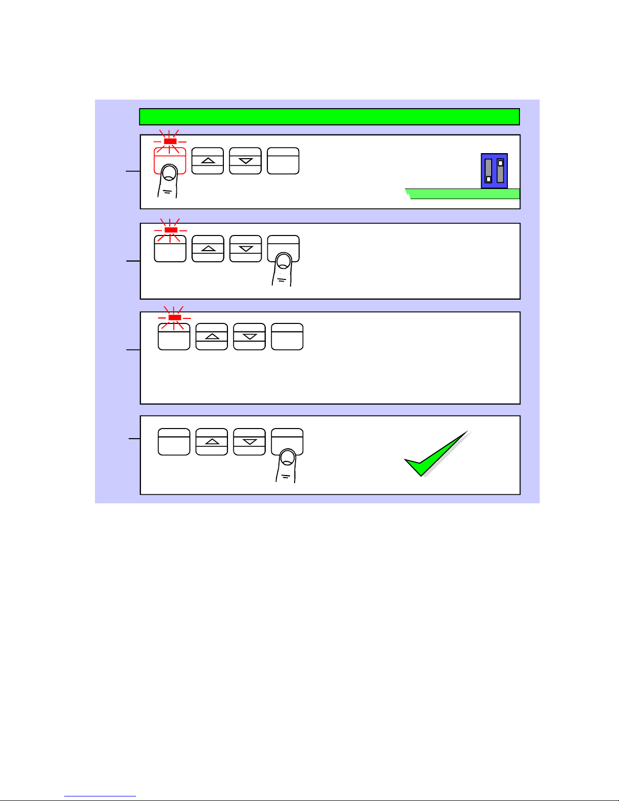
19
Direct Calibration - Zero Setting
How to calibrate the ZERO point.
You can set Zero first, if you prefer, but you will not be able to change the decimal point
position in the ZERO calibration step.
This will not be an issue if your zero calibration reading is 0, but may become
confusing otherwise.
When you have finished your calibration, please remember to put the calibration
lockout switch in its ON position, to protect your settings.
OK
Max/Min Reset
Lockout Switch must be OFF
Set1
Set2 Output
Alarms
Digit
OK
Max/Min Reset
Apply the lowest calibration signal
you can achieve, ideally 0% of
system capacity.
Now press OK
Set1
Set2 Output
Alarms
Digit
OK
Max/Min
Reset
You can now set the display value you
want to see - use DIGIT to select each
digit in turn, and the UP or DOWN
arrow to increase or decrease each
digit’s value, as required.
Set1
Set2 Output
Alarms
Digit
OK
Max/Min
Reset
Press to accept
1
2
3
4
Done!
This feature is available in Easy and Advanced Modes
Display shows direCt
followed by set Lo
OFF
Circuit board ON
Set1 Set2 Output Alarms
Digit
Press 3 seconds
Page 20
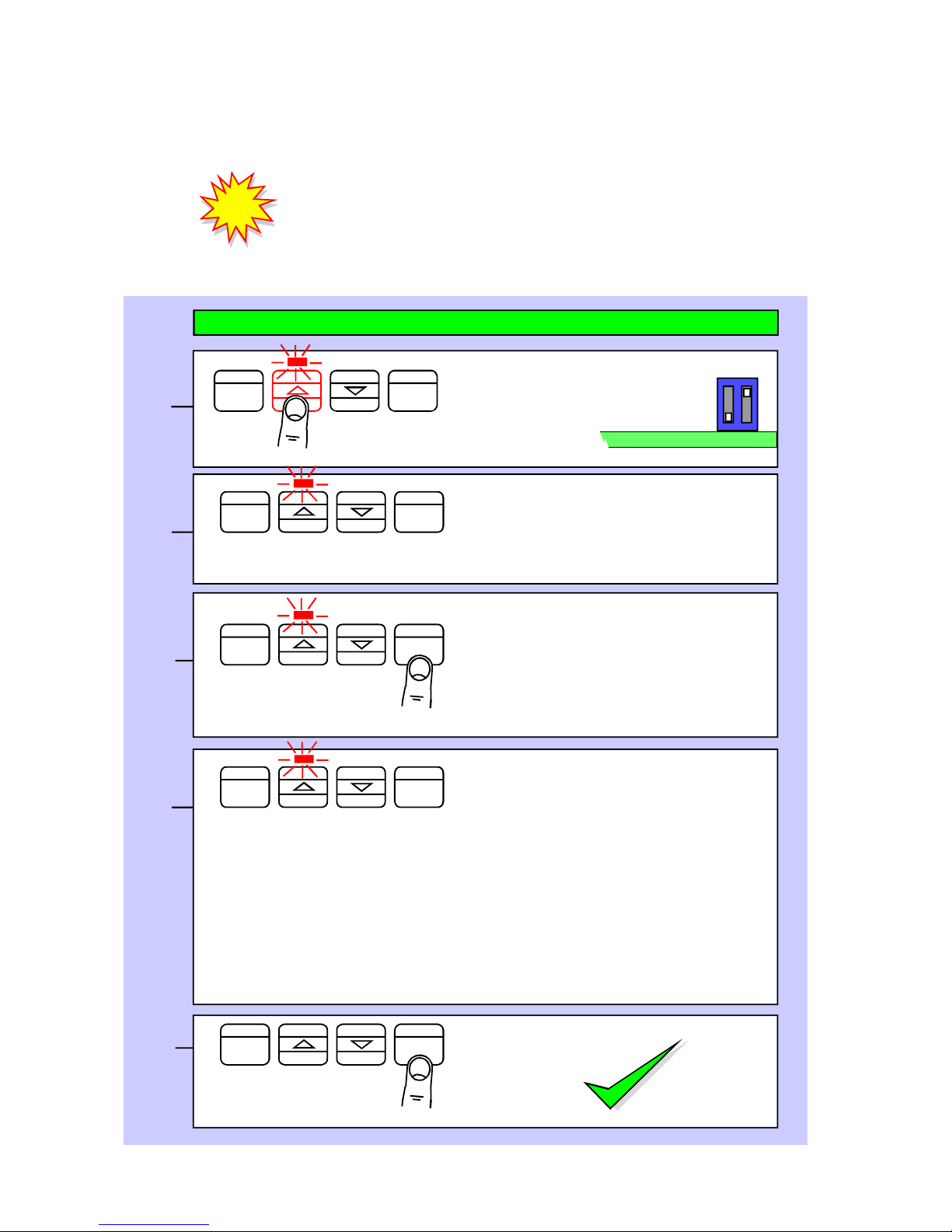
20
Max/Min Reset
Theoretical Cal. - Decimal Point & Full Scale
This is when you type in the sensor’s theoretical signal level at the top and bottom of
its range and the value to display, for each signal level.
If you have not done so before, please select Theoretical Calibration
mode from the Meter Calibration page AND choose whether your
input is current or voltage.
First we recommend you set the FULL SCALE calibration ...
Lockout Switch must be OFF
1
2
3
4
5
Set1 Set2 Output Alarms
Digit
OK
Max/Min
Reset
You can now specify the maximum
input signal. Use DIGIT to select each
digit in turn, and the UP or DOWN
arrow to increase or decrease each
digit’s value, as required. eg set
20.0000 if your input is 4-20mA
Set1 Set2 Output Alarms
Digit
OK
Max/Min
Reset
Press to accept
Set1 Set2 Output Alarms
Digit
OK
Max/Min
Reset
Display now shows rd Hi briefly. You
can now specify the maximum reading
and decimal point position. Press Set2
button for 3 seconds to set decimal point
position. Use up and down arrows to
move the decimal point and press OK
when done. Then, use DIGIT to select
each digit in turn, and the UP or DOWN
arrow to increase or decrease each
digit’s value, as required. eg set 100.000
if your display range is 0 to 100.000
Set1
Set2 Output
Alarms
Digit
OK
Max/Min
Reset
Press to accept
Done!
!
!
This feature is available in Easy and Advanced Modes
Defaults are
4-20mA = 0-100.00 for dCA
and
0-10V = 0-100.00 for dC V
Display shows theor followed by
dC A or dC V, depending on
whether you have chosen current or
voltage input, then In Hi
OFF
Circuit board ON
Set1
Set2 Output
Alarms
Digit
OK
Press 3 seconds
Page 21
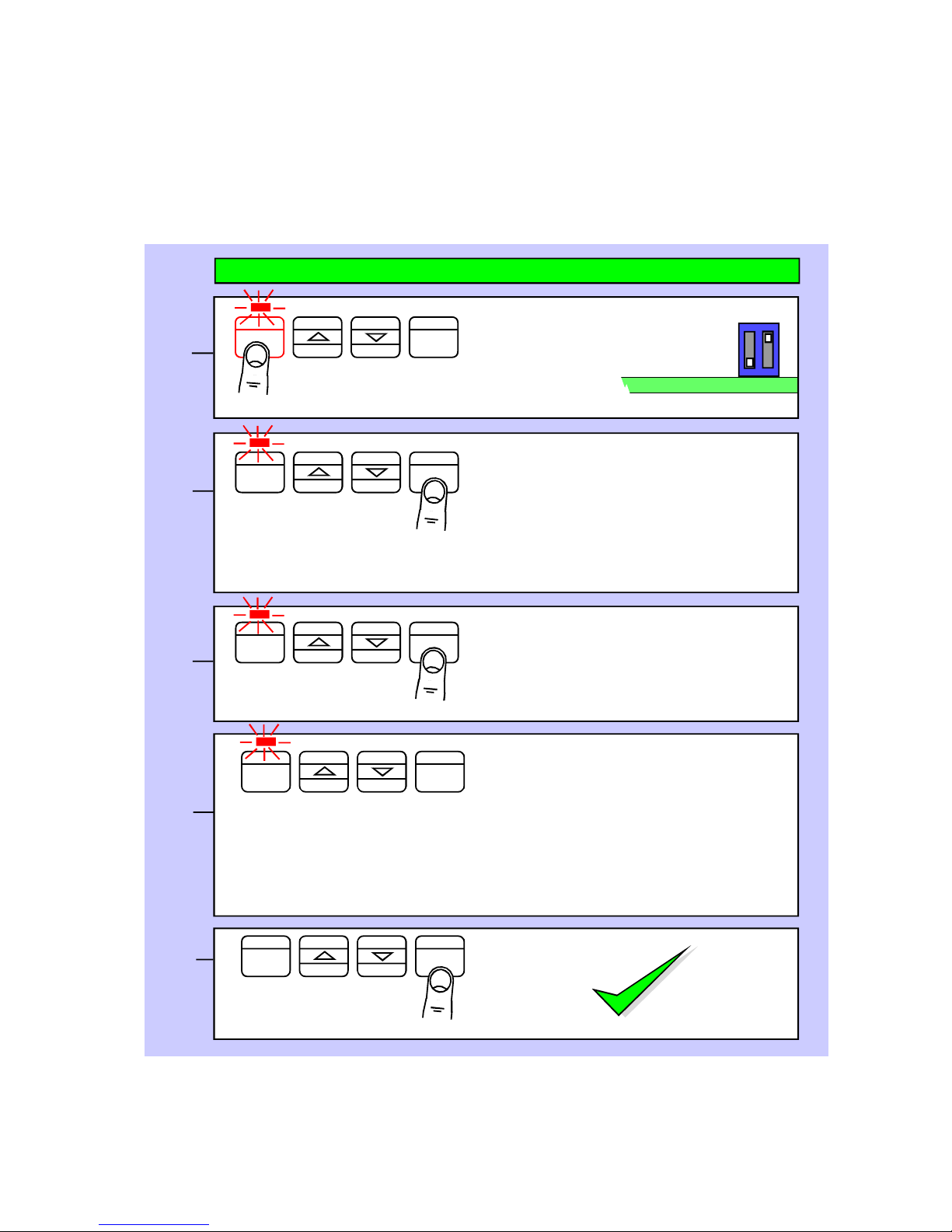
21
Set1 Set2 Output Alarms
Digit
OK
Max/Min Reset
Lockout Switch must be OFF
Press 3 seconds
Set1 Set2 Output Alarms
Digit
OK
Max/Min Reset
Press OK. You can now specify the
lowest input signal. Use DIGIT to
select each digit in turn, and the UP
or DOWN arrow to increase or
decrease each digit’s value, as
required. eg set 04.0000 if your
input is 4-20mA
Set1 Set2 Output Alarms
Digit
OK
Max/Min Reset
Set1 Set2 Output Alarms
Digit
OK
Max/Min
Reset
Press to accept
1
2
3
4
5
Press to accept
Set1
Set2 Output
Alarms
Digit
OK
Max/Min
Reset
Display now shows rd Lo briefly. You
can now specify the low reading.
Use DIGIT to select each digit in turn,
and the UP or DOWN arrow to increase
or decrease each digit’s value, as re-
quired. eg set 000.000 if your display
range is 0 to 100.000
Theoretical Calibration - Low end calibration
This is when you type in the sensor’s theoretical signal level at the top and bottom of
its range and the value to display, for each signal level.
If you have not done so before, please select Theoretical Calibration mode
from the Meter Calibration page.
Done!
You can set Zero first, if you prefer, but you will not be able to change the decimal
point position in the ZERO calibration step. This will not be an issue if your zero
calibration reading is 0, but may become confusing otherwise.
This feature is available in Easy and Advanced Modes
OFF
Circuit board ON
Display shows theor
followed by dC A or dC V , depending
on whether you have chosen current or
voltage input, then In Lo
Page 22
22
Set1
Set2 Output
Alarms
Digit
OK
Max/Min Reset
Sensor Drift correction
If your system is normally reading 0, for example as is typical with platform scales or a
torque meter, you may find a small amount of sensor drift caused by changes in
temperature, ageing etc.
We can automatically correct for slow, long term drift, by comparing your signal to 0 every
30 seconds, and re-calibrating to remove any detected movement.
This does not affect the sensititivity of your system, and is only applied for readings less
than 8 least-significant counts.
The corrected value is stored in non-volatile memory, so that any drift trend will be re-applied after you have switched off the meter.
Lockout Switch must be OFF
Press together, briefly
Set1
Set2 Output
Alarms
Digit
OK
Max/Min Reset
Press OK button briefly and repeatedly until you see drift.0 or
drift.1 displayed.
Set1 Set2 Output Alarms
Digit
OK
Max/Min
Reset
Press briefly to toggle
1
2
3
4
Set1 Set2 Output Alarms
Digit
OK
Max/Min
Reset
Done!
Press DOWN or UP button to toggle
between drift.0 or drift.1
drift.0 = No Correction (Default)
drift.1 = Correction is active
This feature is available in Easy and Advanced Modes
Press to accept
OFF
Circuit board ON
Page 23
23
Logic input connections and front buttons
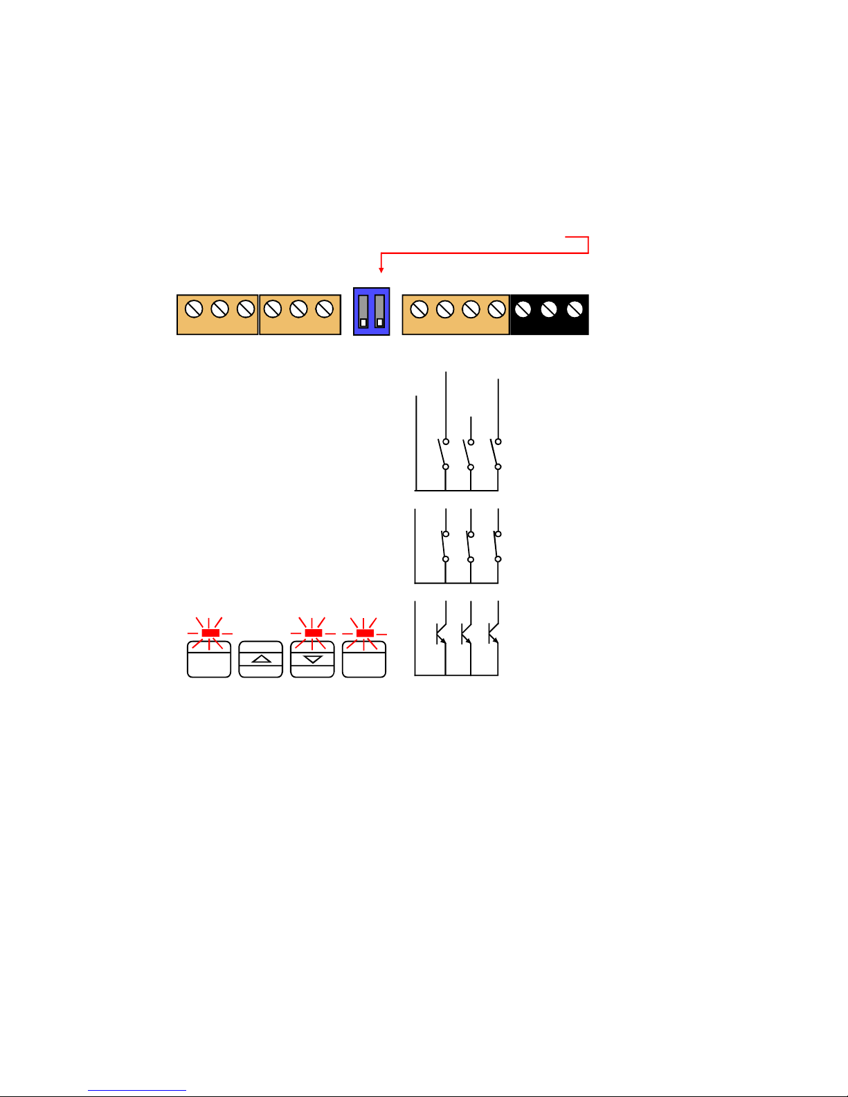
The logic input provides a 5V DC signal. When you connect this to common, a current of
1mA will flow. Because this is a small signal, we recommend you use switches with gold
plated contacts, or self cleaning contacts, for best long term reliability.
The logic inputs are not galvanically isolated from the input signal.
The logic inputs are only activated when the lockout switch is ON
Logic Inputs Power
Signal I/P & Excitation
1 2 3 4 5 6 7 8 9 10 11 12 13
Normally open (disables front
panel Tare, Peak/Valley and
Reset buttons)
Normally closed (this enables
front panel Tare, Peak Valley and
Reset buttons also) Or simply link
NPN (could be opto-isolators if
you need the logic control lines to
be galvanically isolated from the
input signal.
To enable the front panel buttons, you must connect the logic input for that function to
common. If you want to have both front panel and remote tare, reset and peak/valley functions, you can use normally closed pushbuttons for the remote switches.
Tare = Tares display to 0. Often used in weighing systems to zero a display
prior to making a measurement. Net weight is shown once tared.
When a display has been tared the small LED above the Set1
button will be illuminated.
Peak/Valley = Allows you to view the maximum and minimum values
which have been displayed since last reset. 0% LED illuminates
whenshowing valley, 100% LED illuminates when showing peak.
Reset. = This clears any tare, peak, valley, alarm latch
ON
OFF
Set1 Set2 Output Alarms
Digit
OK
Max/Min
Reset
Showing Nett value (steady)
Showing Gross value (flashing)
Showing Valley
Showing Peak
Common
Tare
Peak/Valley
Reset
Page 24
24
Set1
Set2 Output
Alarms
Digit
OK
Max/Min Reset
Factory Defaults
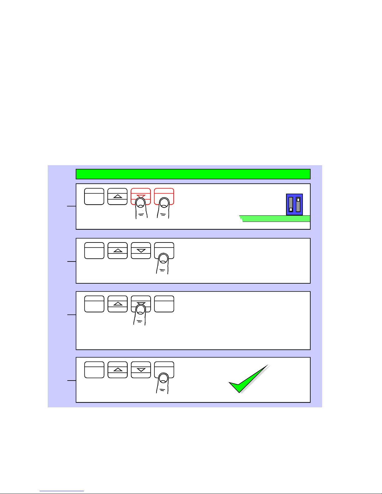
You can return the display to its factory default conditions whenever you wish. If you do so,
you will permanently loose all your settings and will need to start from the beginning again.
The calibration Audit Counter will NOT be reset, there is no way provided to reset this value,
as it is intended as a secure record to indicate whether changes have been made to the
display since it was last calibrated..
Lockout Switch must be OFF
Set1
Set2 Output
Alarms
Digit
OK
Max/Min Reset
Set1 Set2 Output Alarms
Digit
OK
Max/Min Reset
Press to accept
1
2
3
Done!
This feature is available in Easy and Advanced Modes
Display shows :-
defs n (Defaults no)
Press the DOWN button to change the
display to defs y (Defaults Yes) if you
want to return to default conditions.
Press together for 3 seconds
OFF
Circuit board ON
Calibration audit number
Your display includes a non-resettable counter which increments each time you make a
change to the display’s calibration. This is useful if you want to check whether a display has
been altered since it was last calibrated.
The Calibration audit number starts at CAL 01 up to CAL FF allowing up to 255 alterations
to be recorded. Whenever you want to check the calibration audit number, press and hold
the 2 outer buttons (Set1 + Alarms) for more than 3 seconds.
Set1
Set2 Output
Alarms
Digit
OK
Max/Min Reset
Done!
1
Press together for 3 seconds
Page 25
25
Set1
Set2 Output
Alarms
Digit
OK
Max/Min Reset
Signal Filtering / Averaging
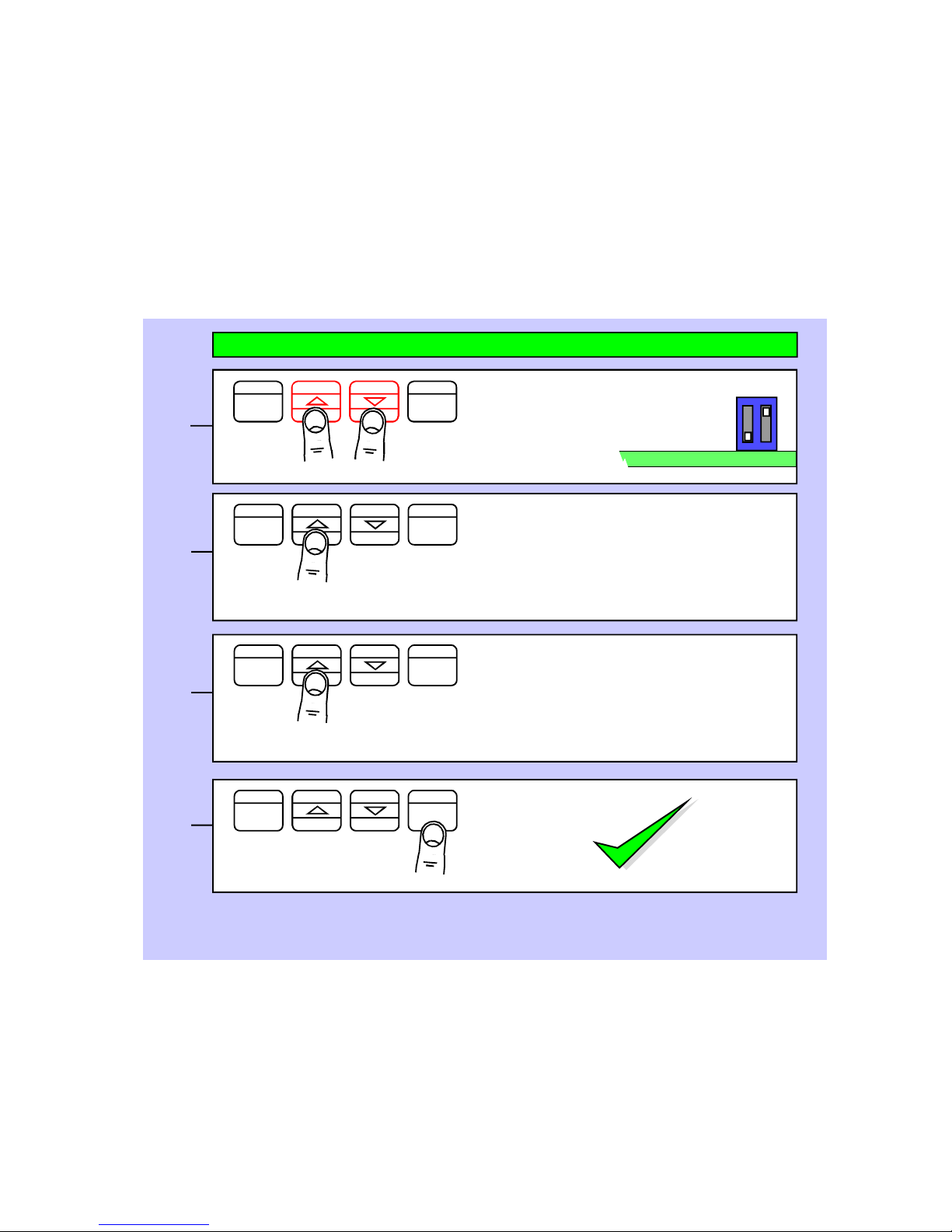
You can adjust the filtering time constant to reduce the effect of noise or instability on your
input signal.
A larger FIL value will give a more stable display, but the response to signal changes will be
slower.
Because your output options, such as analogue output, alarm relays and serial output are all
derived from the displayed value, they will respond at the same rate as the filtered display.
Lockout Switch must be OFF
Press 3 seconds
Set1
Set2 Output
Alarms
Digit
OK
Max/Min Reset
Display shows FIL.XX.X where
XX.X is the time constant in seconds.
Use the UP or DOWN button to
increase or decrease this value
(Default = FIl. 00.0)
Set1
Set2 Output
Alarms
Digit
OK
Max/Min Reset
Press to accept
1
2
3
4
Done!
See also Filter Jump setting in the Advanced Menu, if your signal is particularly noisy and
you cannot get sufficient smoothing with this filter.
This feature is available in Easy and Advanced Modes
OFF
Circuit board ON
Set1
Set2 Output
Alarms
Digit
OK
Max/Min
Reset
Display shows HFI.X where X is
the amount of basic filtering.
A=Low b=Medium C=High d=Most
(Default = HFI.C)
Select, then press OK to accept
Select, then press OK to accept
Page 26
26
Set1
Set2 Output
Alarms
Digit
OK
Max/Min
Reset
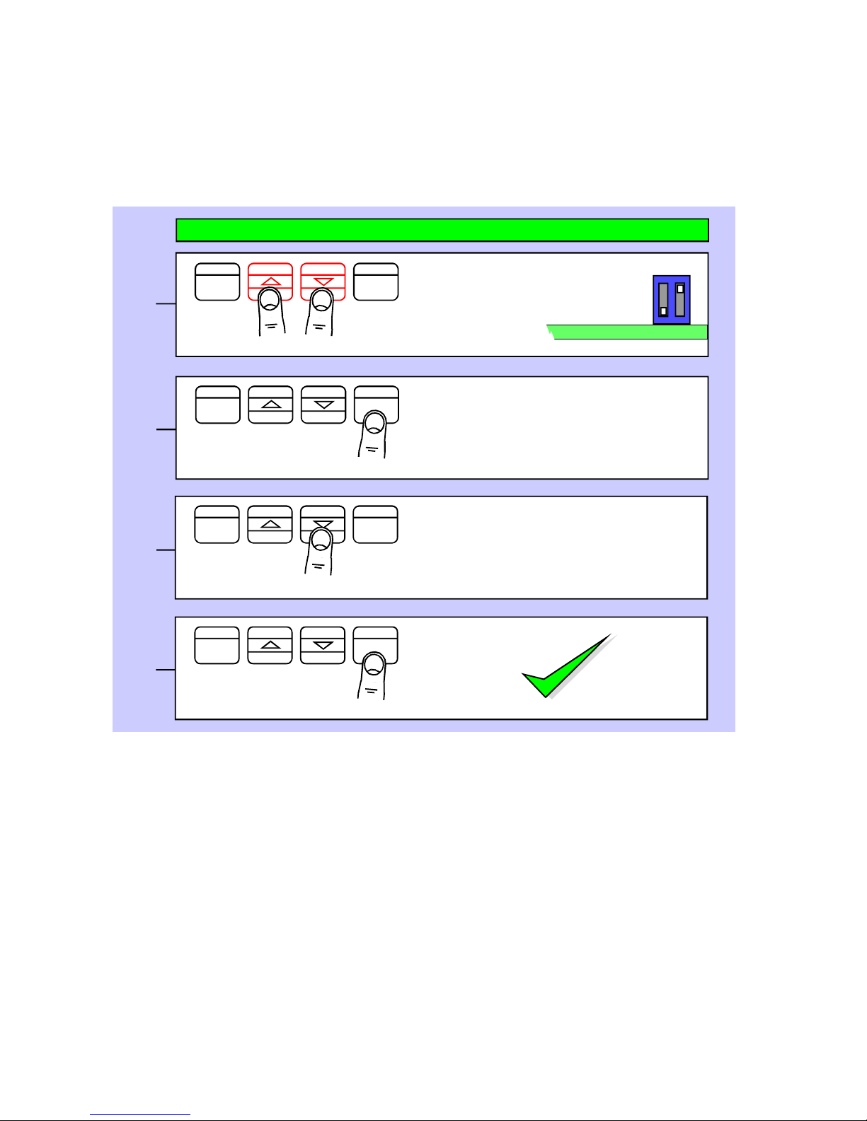
Last Digit rounding up by 1, 2, 5, 10, 20 or 50
You can adjust the way the display rounds up, which is useful if you want to display a very
large number, but do not want jitter on the last digit.
The display can be set to round up to the nearest 1 (no rounding) 2, 5, 10, 20 or 50
Lockout Switch must be OFF
Press 3 seconds
Set1
Set2 Output
Alarms
Digit
OK
Max/Min
Reset
Press repeatedly until you see
LSt X where X is either 1,2,5,10,20
or 50
(Default = LSt 1))
1
2
3
4
This feature is available in Easy and Advanced Modes
Set1
Set2 Output
Alarms
Digit
OK
Max/Min
Reset
Press repeatedly to change the LST
value to the one you want
Set1 Set2 Output Alarms
Digit
OK
Max/Min Reset
Done!
OFF
Circuit board ON
Page 27
27
Set1 Set2 Output Alarms
Digit
OK
Max/Min
Reset
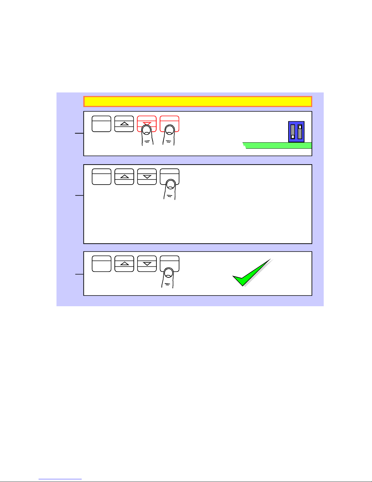
Menu timeout adjustment
The display has a default timeout of 60 seconds, to allow you sufficient time to refer to the
manual between key operations.
You can make this period shorter, if you wish, once you become more familiar with the
setup method.
Lockout Switch must be OFF
Press together, briefly
Set1 Set2 Output Alarms
Digit
OK
Max/Min
Reset
Press repeatedly until you see
dLAY. XX where XX is the delay in
seconds. Choices are ...
dL A y.1 0
dL A y. 20
dL A y. 30
dLAy. 60 (default)
1
2
3
Set1 Set2 Output Alarms
Digit
OK
Max/Min
Reset
Done!
!! This feature is available in Advanced Mode only !!
Press to accept
OFF
Circuit board ON
Page 28
28
Set1 Set2 Output Alarms
Digit
OK
Max/Min
Reset
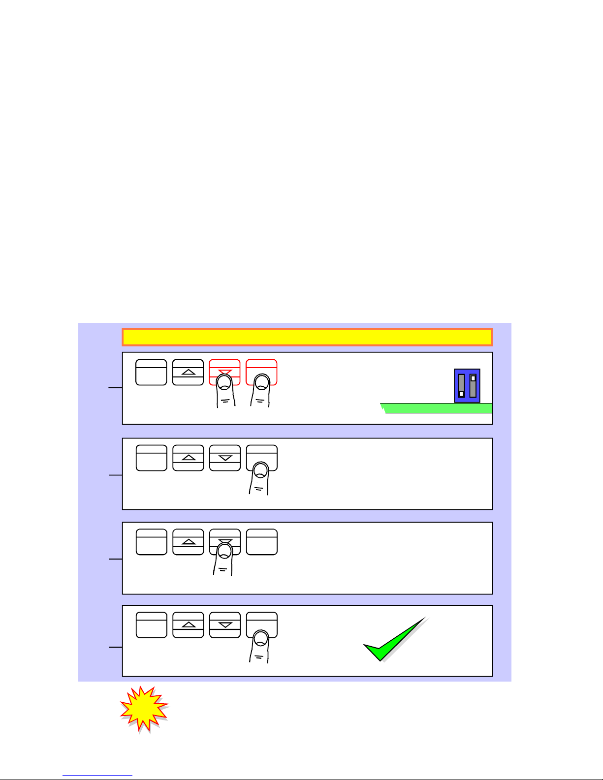
Bootup routine choices
When you switch on your meter, it can be set to power up with 3 possible summary message combinations.
The choices are:-
boot 0 = Segment test, followed by a full summary of software revision,
calibration audit number, model number, installed options.
boot 1 = Segment test followed by model number (Default)
boot 2 = No summary, meter displays the measurement value
immmediately power is applied.
boot 3 = Segment test remains permanently avive, until any button is
pressed.
Lockout Switch must be OFF
Press together, briefly
Set1 Set2 Output Alarms
Digit
OK
Max/Min
Reset
Press OK button briefly and
repeatedly until you see boot 0 or
boot 1 or boot 2 or boot 3
displayed.
Set1
Set2 Output
Alarms
Digit
OK
Max/Min
Reset
Press briefly to toggle
1
2
3
4
Set1
Set2 Output
Alarms
Digit
OK
Max/Min
Reset
Done!
Press DOWN or UP button briefly
and repeatedly to choose from
boot 0 or , boot 1 or boot 2 or
boot 3
!! This feature is available in Advanced Mode only !!
!
!
You can trigger the full summary message whenever you want, without
having to power the meter off, by pressing and holding the 2 outer
buttons (Set1 + Alarms) for more than 3 seconds.
Press to accept
OFF
Circuit board ON
Page 29

29
Error codes and fault finding
--Ur--
--Or--
1. Under Range. The meter is being asked to display a value which is more
negative than its limit of -199999
2. Over Range. The meter is being asked to display a value which is higher
than its limit of 999999
These fault codes could be displayed because the signal is too negative, too
positive, or because there is a wiring error, or because the display’s scaling
has been adjusted to give excessive sensitivity, or because there is a fault in
the display.
a. If you are connecting a 4-20mA signal to the display, please measure the
DC millivolt signal between terminals 2(-) and 3(+) Ideally, you will measure
132mV at 4mA and 660mV at 20mA.
If the voltage is much higher, there may be a problem with the 33 Ohm input
shunt resistor.
You can verify this as follows...
Remove the input signal and power connectors to the meter, and measure
the resistance between terminals 2 and 3. This should be 33 Ohms. If it is
more than this, the resistor has probably been overloaded and burned by
having a voltage connected across it. Please check your field wiring to ensure that no more than 30mA or 1V can be applied to the current input
terminals.
Sometimes excessive current can feed to the current input of the display if
your 2 wire 4-20mA transmitter is faulty or is wired incorrectly, because we
rely on the transmitter to regulate the loop current between 4 and 20mA. The
excitation power supply for the loop may have a much higher capacity than
20mA.
b. If the measurements above were satisfactory, the problem may be caused
by the scaling being too sensitive.
If you are happy to do so, it is a simple matter to reset the display’s scaling to
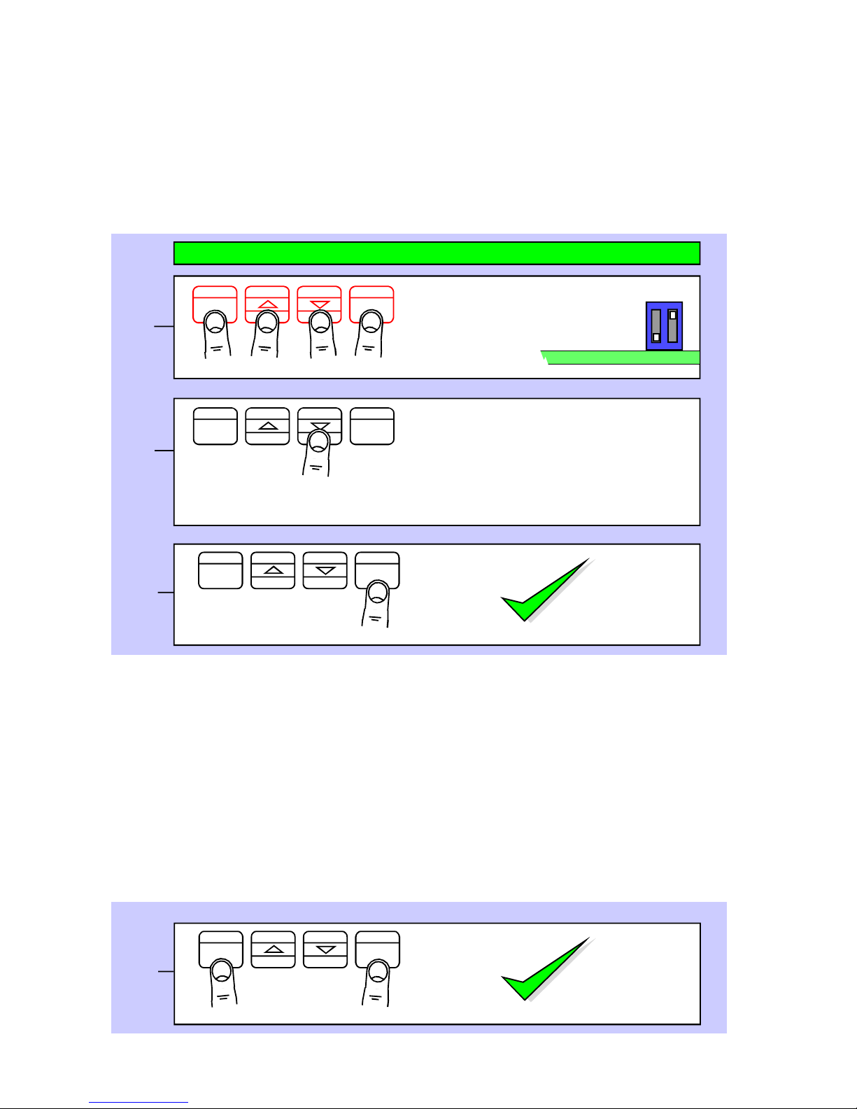
the factory default conditions. Put the lockout switch off and press all 4
buttons together for around 3 seconds until the display shows “dEFS n”.
Then press the UP button once so the display shows “dEFS Y”. Now press
the OK button and the display will be reset to factory defaults.
If still no success, please return the display to us for the attention of our QA
Manager, with a report of what you found, for repair.
Page 30

30
Waste Electrical Electronic Equipment (WEEE)
In Europe, this equipment must be disposed of in accordance with European
Parliamentary Directive 2002/96/EC
This directive encourages recycling and the reduction of waste materials in the
environment.
This means it must be sent to an approved recycling plant if you want to dispose of it.
It must not be thrown away with general rubbish.
If you are unable to dispose of this item locally, you may send it to us for recycling.
Conditions:
1. We will only accept items of our manufacture.
2. You must pay for the transport of the goods to us.
3. We will only accept items if they include a signed declaration by an authorised
person in your organisation, stating that :-
i. The item is safe to handle and has no contaminants which may be
harmful to health.
ii. You wish us to dispose of or destroy the item(s)
Page 31

31
Equipment Specifications
Bezel size 48mm high by 96 mm wide (1/8 DIN)
Panel Cutout 45 mm high by 92 mm wide
Case Depth 125 mm including connectors
Weight 300 grammes
Case Material Black polycarbonate
Connectors Detachable Screw Terminal connectors
Environmental Storage Temperature range -20 to +70C, non condensing
Operating temperature range 0 to 50C, non condensing
Front sealed IP65. Optional cover SPC4 for IP67. Allow 30 minutes
for the meter to achieve thermal equilibrium after switch-on.
Power 100-240 VAC, 45 to 60Hz or 11-30 VDC optional
Burden 10VA maximum
Input Signals (bipolar) 0-10V, 0-5V, 1-5V, 0-10mA, 0-20mA, 4-20mA
Input Resistance 1 Megohm for voltage, 33 Ohms for current inputs
Accuracy +/-0.05% of range
Span tempco 25 ppm/Degree Celsius
Zero Tempco 30 ppm/Degree Celsius
24V Excitation voltage 24VDC nominal rated at 60mA
10V Excitation voltage 10VDC nominal rated at 20mA
Filtering / smoothing Selectable time constants of 0 to 25 seconds.
A/D conversion Sigma-Delta 10 conversions per second, 50/60Hz rejection
Resolution 1 in 400 000 max. over full range
Display update rate 10 readings per second.
Display Range (max) -199999 to +199999, depending on available signal level.
9122-2470
S11 S7
S12 S13
Input Conditioner Board
S2
S8
S3
S9
S10
S4
Excitation voltages
5V DC Link S11. Open S7 and S12 and S13
10V DC Link S11 and S7. Open S12 and S13 (default)
Excitation Ratiometry
Ratiometric. Link S6. Open S1 (default)
Non ratiometric. Link S1. Open S6
S6 S1
Default Input configuration switches
Link S8, S9, S10, S11. Open S2, S3, S4, S12
S5
Input board jumper-switch selection
Page 32

32
Record of Revisions
6 September 2010 Version F0.18 Software released. Manual format revised to improve
clarity and segregate easy from advanced menu functions. Optional
outputs now described in their own dedicated manuals. DIN Rail mounting option
added. Cabling guidance added.
17 November 2010 Version F00.19 Software released. Intended for use with 9122-2470 input board,
having switched capacitor input filter feature. Code will auto detect this board. If a
previous version board is installed, the meter will skip switched capaciter filter section
of menu.
The newly released 9122-2470 input board allows selection of 5V or 10V excitation.
26 November 2010 Version F00.20 Software released. Allows serial data output to derived fron Net or
Gross measurement on full featured INT2-L versions
14 February 2011 Version F00.21 software released. Adds a permanent segment test routine to bootup
choices
28 February 2011 Warranty increased to 3 years and terms added.
Page 33

33
Notes
Page 34

34
Notes
Page 35

35
Notes
Page 36

36
Declaration of CE Conformity
Conditions
The meters are permitted a worst case error of 1% of A/D range during electro-magnetic
disturbance, and must recover automatically when disturbance ceases without the need for
human intervention, such as resetting, power-down etc.
The meters covered by this certificate must be installed in adherence to the following
conditions :-
Signal cabling shall be routed separately to power carrying cabling (includes relay output
wiring)
All signal cabling shall be screened. The screen shall only be terminated to the power earth
terminal at the meter end of the cable.
Declared as true and correct, for and on behalf of London Electronics Ltd.
J.R.Lees Director
This is to confirm that the Product covered by this declaration has been designed and
manufactured to meet the limits of the following EMC Standard :
EN61326-1:1997
and has been designed to meet the applicable sections of the following safety standards
EN61010-1:2001
Declaration Reference : INTUITIVE Mk2
Issue Date : 30 April 2007
Products Covered : INTUITIVE Mk2 series
Title : DOC-INTUITIVE2
 Loading...