

Page 1
1
NPN, PNP, Contact Closure, TTL, CMOS logic Inputs
Including Sensor Excitation and RS485 Data Output
Scaleable Ratemeters
R175X Series of Large Displays
Rev. 11.0 30 June 2008
Doc. R17CE.pm5
User's Manual
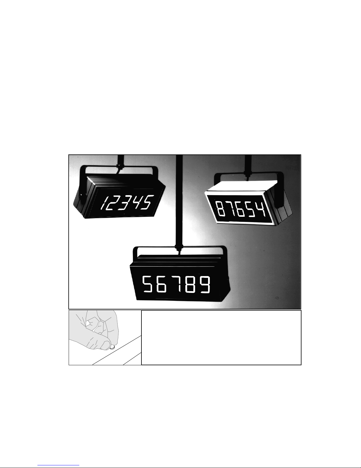
Rear case screws - please note
The rear panel is held in place with finger-screws,
which only need to be gently tightened. Do not use
tools to tighten or loosen the screws, as this
could cause damage to the internal threads.
London Electronics Limited
Thorncote Road, Near Sandy, Bedfordshire SG19 1PU
Tel +44(0)1767 626444 Fax +44(0)1767 626446
www.london-electronics.com [email protected]
Page 2

2
CONTENTS.
SECTION
PAGE
INTRODUCTION................................................................................................ 3
1.0 UNPACKING AND INSPECTION................................................... 4
2.0 GENERAL INFORMATION............................................................ 4
2.1 General specifications........................................................................... 5
3.0 INTERNAL CABLES........................................................................ 6
3.1 Signal cables......................................................................................... 6
3.2 Mains cables......................................................................................... 6
4.0 DETAILED OPERATING INFORMATION
4.1 Pulse I/P Selection................................................................................ 7
4.1.1 Jumper Functions and Positions............................................................ 7
4.2 Typical Input connections..................................................................... 8
4.3 RS485 output option notes..................................................................... 8
4.4 Contact Closure Remote Programmer connections............................... 9
4.5 Programming your display................................................................... 9
4.6 The Programming Menu & Brightness adjustment................................ 10
4.7 Programming Flow Chart..................................................................... 11
4.8 Application Example............................................................................ 12
5.0 INSTALLATION............................................................................... 13
5.1 Mounting positions.............................................................................. 14
5.2 Panel mounting.................................................................................... 14
5.3 Wall mounting...................................................................................... 14
5.4 Suspension mounting........................................................................... 14
5.5 Multiple display mounting.................................................................... 15
6.0 TROUBLE SHOOTING AND MAINTENANCE............................ 15
7.0 SAFETY CONSIDERATIONS..
N................................................ 15
8.0 WARRANTY...................................................................................... 16
9.0 OTHER LONDON PRODUCTS...................................................... 17
10.0 AND FINALLY................................................................................... 18
Page 3

3
THE RATEMETER MODEL - R175X
INTRODUCTION
The R175X is one member of a broad family of Large Displays. The family is the '1700 Series', and
the part number tells you a little about the display's function......
R175X
This model is intended for large measurement display use. It accepts the most commonly encountered
proximity sensors, of NPN or PNP type, contact closures, TTL and CMOS logic levels.
The incoming signal can be measured over a choice of gate times, and the readings can be averaged
over a number of gate periods, givin very long effective average measurements. This allows the rate
over an 8 hour shift to be accurately shown, for example, though the display is similarly well suited
to displaying powerline frequency.
If specifically ordered , we can supply the displays with a silk screened legend identifying the
measurement being displayed, for example, units/hour, bottles/shift etc..
An optional RS485 output is available , useful for feeding remote mimic displays. If you require serial input
only, and do not require analogue input, a simpler, model is available, S17XX series. The serial input
models can have 5 or 7 digits.
The configuration settings and calibration constants of the display are stored in non-volatile E2PROM
memory, which is retained for at least 10 years. Change to the settings is achieved by way of remote
contact closure inputs, allowing alteration of the unit’s configuration menu, calibration and brightness.
The case is sealed to IP65, and the lens is 4mm thick polycarbonate, making it ideal for use in food
industry washdown applications.
'17' identifies the model as
being in the 1700 series
Tells us how many digits the display has
(5 always for this model)
Tells us how many
inches high the digits are
'R' for
Rate I/P
Page 4

4
PLEASE check the carton’s contents as soon as possible after receipt, to detect any transit damage or
losses.Unpack the contents and check each item in the box against the check list below to make sure you
have all items.
Check List :
Handbook
Display
Mounting kit ( where appropriate )
Programming Unit ( If Ordered )
In the event of damage, please contact the carrier and advise our sales office of the fault.
Please retain the carton packing material, for future possible use.
2.0 GENERAL INFORMATION
This handbook covers the Ratemeter model of the 1700 series large displays.
The 1700 series is a family of units for broadcasting process values and data on easy to read large
7 segment displays. Character heights of 2", 4" or 6" are standard, and, dependent on type, displays
are 5 or 7 digit. Extra-large and Daylight viewing displays are available to special order.
The enclosures for the displays are of welded UPVC material with tough lenses, providing certified
protection to IP65/66 for the internal electronics. Thermostatic heater options may be installed for
outdoor mounting in cold climates.
Case colours are white or black.
The units incorporate a 95 to 265VAC power supply ( Which can be used on DC in the range 100 to
300 VDC ) for operation off any mains source without the need to re-configure.
Display brightness is settable to 4 levels to accommodate differing ambient light conditions and the
3 standard character heights provide a choice of viewing distances of up to 20, 40 and 60 metres.
Other character heights and brightnesses are available to special order.
The large displays are based around a common power and control card which is linked to display
units of different sizes.
Instrument behaviour is set by way of remote contact closure pushbuttons, which provide access to
and alteration of the instrument’s menu, and the settings are stored in 10 year non-volatile memory.
Page 5

5
2.1 GENERAL SPECIFICATIONS
Display type Scaleable rate/frequency meter, adjustable averaging and
resolution
Signal inputs Contact closure, NPN, PNP, 5V TTL/CMOS, 24VDC
Debounce jumpers available, limiting inputs to <10Hz.
Max I/P rate without debounce = 10Khz.
Input Resistances: 2200 Ohms if internal pull-up/down enabled. Otherwise 10M
Excitation Supply: Nominally 13VDC at 60mA max.
Accuracy: 0.01% of range , 20ppm/oC Quartz Crystal controlled
Scaling Scale fully adjustable remotely.
Decimal point position selectable
Optional Signal Output RS485 at 300, 1200, 2400 or 9600 Baud
Data format Serial ASCII at 300,1200,2400 or 9600 baud; 1 start bit,
8data ( or 7 data plus parity ) and 1 or more stop bits.
Handshake No handshake, unit always transmits data
Case material: UPVC, White or Black
Case size:(mm WxH) 5 digit 7 digit
2" 288x120 384x120
4" 480x168 672x168
6" 624x192 864x192
Case depth : 90mm ( 115 mm including rear cable/glands)
Weight : 5 digit 7 digit
2" 2.5Kg 3Kg
4" 4.5Kg 5Kg
6" 5.0Kg 6Kg
Display type:
2" digit height High efficiency red LED 57mm high 7 segment display tiles
4" digit height Ultrabright red LED 102mm high 7 segment display tiles
6" digit height 144mm high characters formed from twinned individual
5mm round red LEDs
Daylight viewing versions, whether 2", 4" or 6" are made up of individual 5mm round lensed LED's
Power supply : 95-264VAC, 100 to 300 VDC, Via Rectifier, non-specific polarity
Power consumption : 20W typ. without thermostatic heater.
Page 6
6
3.0 INTERNAL CABLES
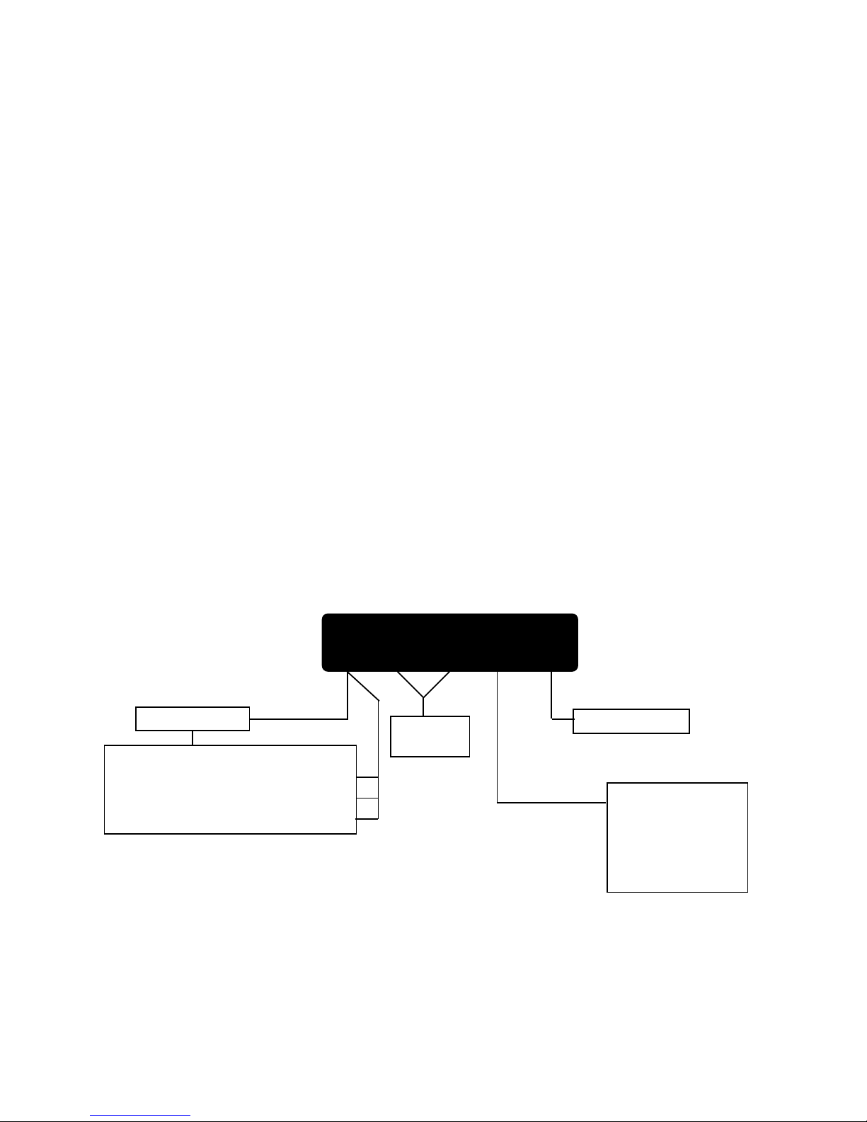
The units are supplied with approximately 2 metres of free ended cable for mains, signal and serial ports.
You may connect your own cable to this, via a junction box, or completely remove the supplied cable and
install your own.
REMEMBER The signals you will be feeding to the displays are quite small in comparison to some of the
undesirable ‘noise’ generated by certain types of common electrical equipment. To obtain the highest degree
of accuracy and reliability from your indication equipment, we strongly suggest that you....
DO NOT run signal cables adjacent to power/switching lines or near equipment liable to generate large
amounts of electrical noise, such as contactors, solenoids, fluorescent tubes, discharge lamps, motor control
equipment, etc.
Do use screened, twisted-pair extension cable to minimise the amount of noise being fed into the display.
WARNING: RISK OF LETHAL ELECTRICAL SHOCK
YOU MAY NEED TO OPEN THE CASE TO ALTER JUMPER POSITIONS OR TO PANEL MOUNT
THE DISPLAY. BEFORE COMMENCING TO OPEN THE CASE YOU MUST ENSURE THAT
POWER HAS BEEN DISCONNECTED, AND MUST ENSURE THAT POWER CAN IN NO
CIRCUMSTANCES BE RE-APPLIED TO THE DEVICE WHILST THE CASE IS OPEN.
3.1 SIGNAL CABLES
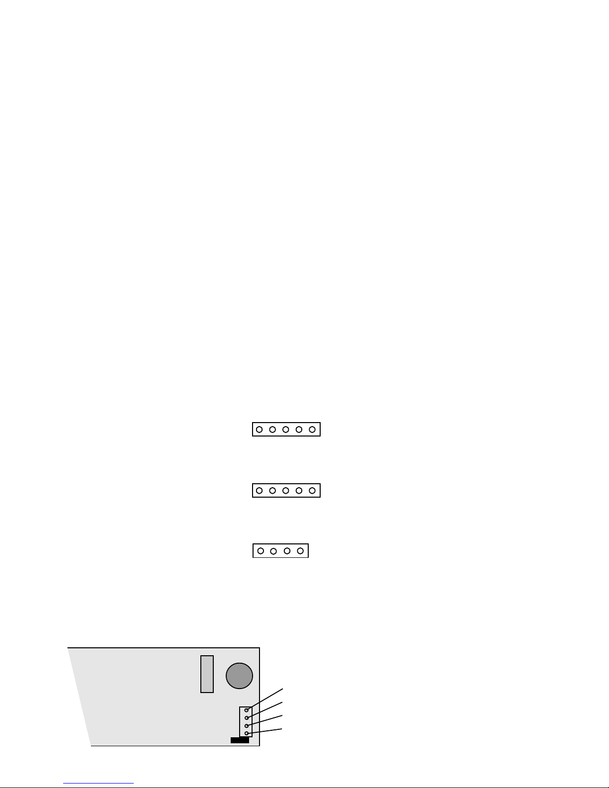
The signal and data connectors are at the left hand end of the power and control card. They are connected
to extension cables, which are accessible from the rear of the display.
Do not earth the screen or braid of the input, data output or programmer cable outside the display, as it
is already internally earthed to the 'screen' terminal.
3.2 MAINS CABLES
The unit incorporates a switching power supply to enable the unit to operate over the full 95 to 265 Volts
range.
The
mains lead must be of 3 core construction, with the earth wire bonded to a good earth.
N
Line (Brown) (+DC for DC option)
Neutral (Blue)(-DC for DC option)
No Connection
Earth (Green/Yellow)
1=Screen Braid
2=Common Blue
3=Input A Red
4=Input B Green
5=+Excitation Yellow
1=Screen Braid
2=Common Red
3=Select Green
4=Increment Blue
5=Menu Yellow
1=Screen Braid
2=Common Yellow
3=Data B Green
4=Data A Blue
Pulse Inputs
Remote Programmer
Optional Serial
Data O/P
1 2 3 4 5
1 2 3 4 5
1 2 3 4
Top Connector P1
Middle Connector P3
Bottom ConnectorP2
P4
Page 7
7
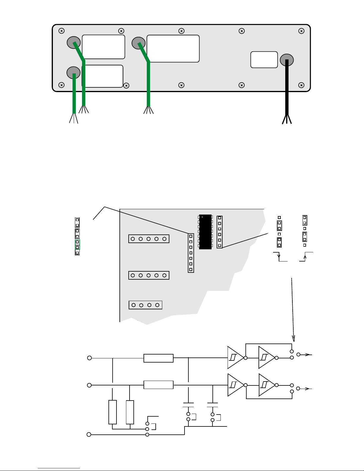
4.1 PULSE INPUT SELECTION
If, when ordering your display you specified the input type required, this will have been set for you prior to
despatch, and should be noted on the label on the rear of the display. If you did not specify the input type,
this will be the factory default of NPN/Contact closure . You can re-configure the meter, by making
internal jumper alterations, to accept PNP, 24VDC, TTL etc.
4.1.1 JUMPER FUNCTIONS AND POSITIONS
The internal circuitry is arranged as follows:-
Power
Brown = AC Hi
Blue = AC Lo
Gn/Yw = Ground
Remote Programmer
Pulse Input
Red = Common
Yellow =Menu/Reset
Green = Select
Blue = Increment
Blue = A
Green = B
Yellow = Comm.
Serial O/P Option
Yellow = + Sig.Excitation
Red = Input A
Green = Input B
Blue = Common (-)
Fit to give Debounce I/P A
Fit to give Debounce I/P B
Pull-up
Pull-down
For no debounce, remove
appropriate jumper. Debounce
limits
input pulse rate to approx. 10Hz.
max
0V
+ Excitation
2K2
2K2
100K
100K
0.22uF
0.22uF
74HC14
Debounce jumpers
Pull up/down jumper
Comm.
I/P B
I/P A
74HC14
To processor
Pull-up
Pull-down
P1 Pulse inputs
P3 Programmer
P2 Serial output
option
Falling
Rising
I/P B
I/P A
Active Edge Selection
Page 8
8
SIGNAL, DATA AND CONTACT CLOSURE CONNECTIONS
4.2
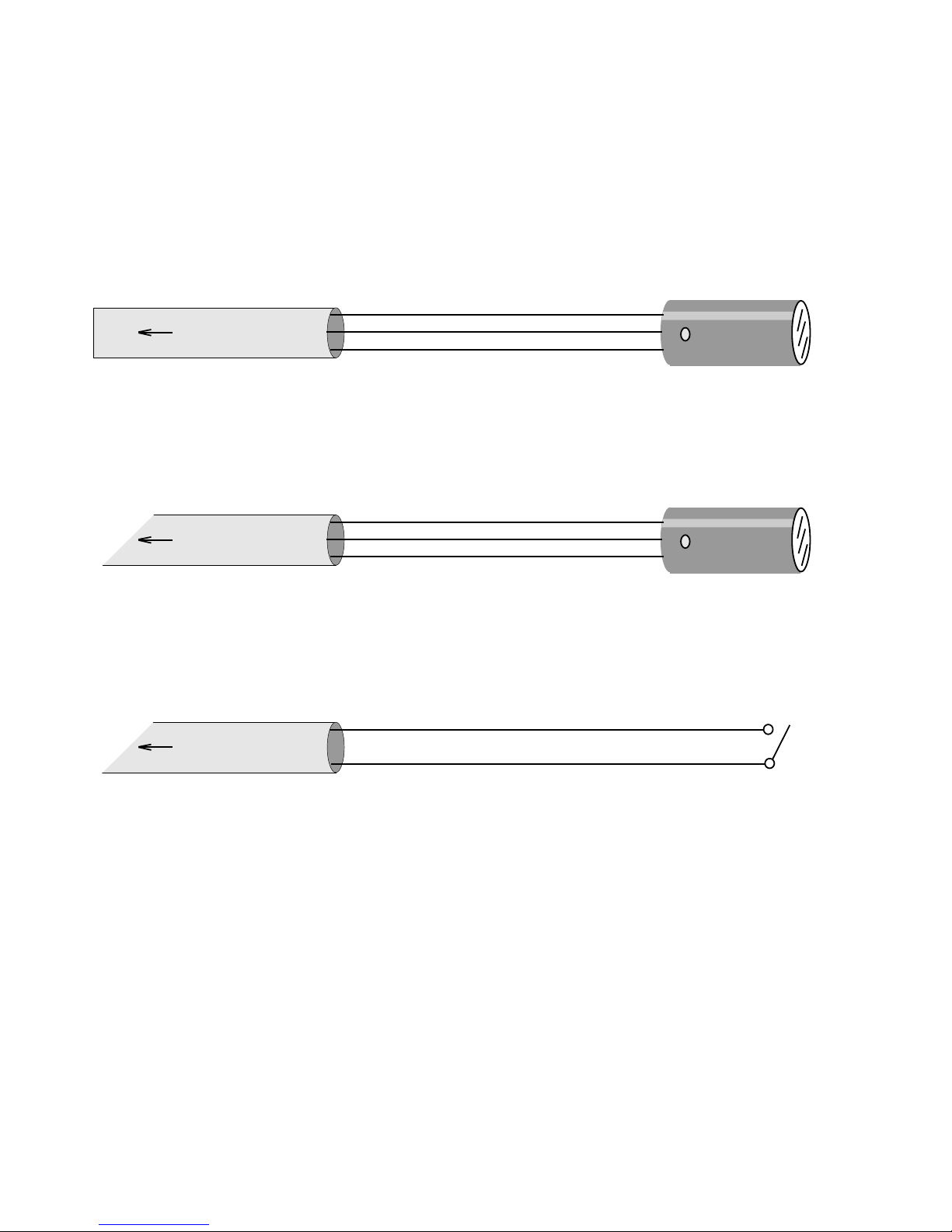
Typical Input Connections
The most common input sensor types are shown below, with a wiring guide, to assist you in the
installation of your totaliser. Only one input is shown, as they both have identical input circuitry.
Because the pullup resistors are not independent ( both inputs will be pulled up or down), you
should choose sensors which require the same pullup format, if using both inputs. In other
words, do not use a PNP sensor for one input and an NPN sensor for the other. You could ,
however, have a NPN sensor for one input and a contact closure for the other.
4.3 RS485 Data Output option (Factory installed only):
The Serial Data O/P cable allows you to feed the measured reading to serial input slave displays,
such as our S17XX series, or small 1/8 DIN SER-06 models, for remote indication purposes.
The output is continuous, with a new string transmitted at roughly 1 second intervals. The format is
the reading itself, including decimal point character, in ASCII, terminated by a Carriage Return.
The data format is 1 start bit, 8 data bits and 1 stop bit. The Baud rate is selectable, and is determined
by the fourth character of the Configuration Number. Extension cable should be screened, high
quality data cable, and should be routed away from sources of electrical noise such as motors,
power cables, inductive devices, discharge lighting circuits etc.
Do not earth the screen of the data
cable, however, as it is already connected to internal earth on the display itself.
Up to 32 slaves having RS485 inputs can be driven from the output port.
NPN
To totaliser
I/P. A Signal
+ Excitation
Common
Sig.
+
-
Jumper Settings: Fit Debounce jumper if input rate is less than 10 per second
Fit Pull-up jumper
If display is to sense when item approaches sensor, fit falling edge jumper.
If display is to sense when item leaves sensor, fit rising edge jumper.
PNP
To totaliser
I/P. A Signal
+ Excitation
Common
Sig.
+
-
Jumper Settings: Fit Debounce jumper if input rate is less than 10 per second
Fit Pull-down jumper
If display is to sense when item approaches sensor, fit rising edge jumper.
If display is to sense when item leaves sensor, fit falling edge jumper.
To totaliser
I/P. A Signal
Common
Jumper Settings: Fit Debounce jumper. Input rate must not be greater than 10 closures per second
Fit Pull-up jumper
If display is to sense when contacts close, fit falling edge jumper.
If display is to sense when contacts open , fit rising edge jumper.
Page 9
9
4.5 PROGRAMMING YOUR DISPLAY
The Ratemeter offers useful flexibility in scaling and display presentation, and all parameters are adjusted
by using the three contact closure programming pushbuttons.
It is worth spending a little time familiarising yourself with the menu and the programming technique
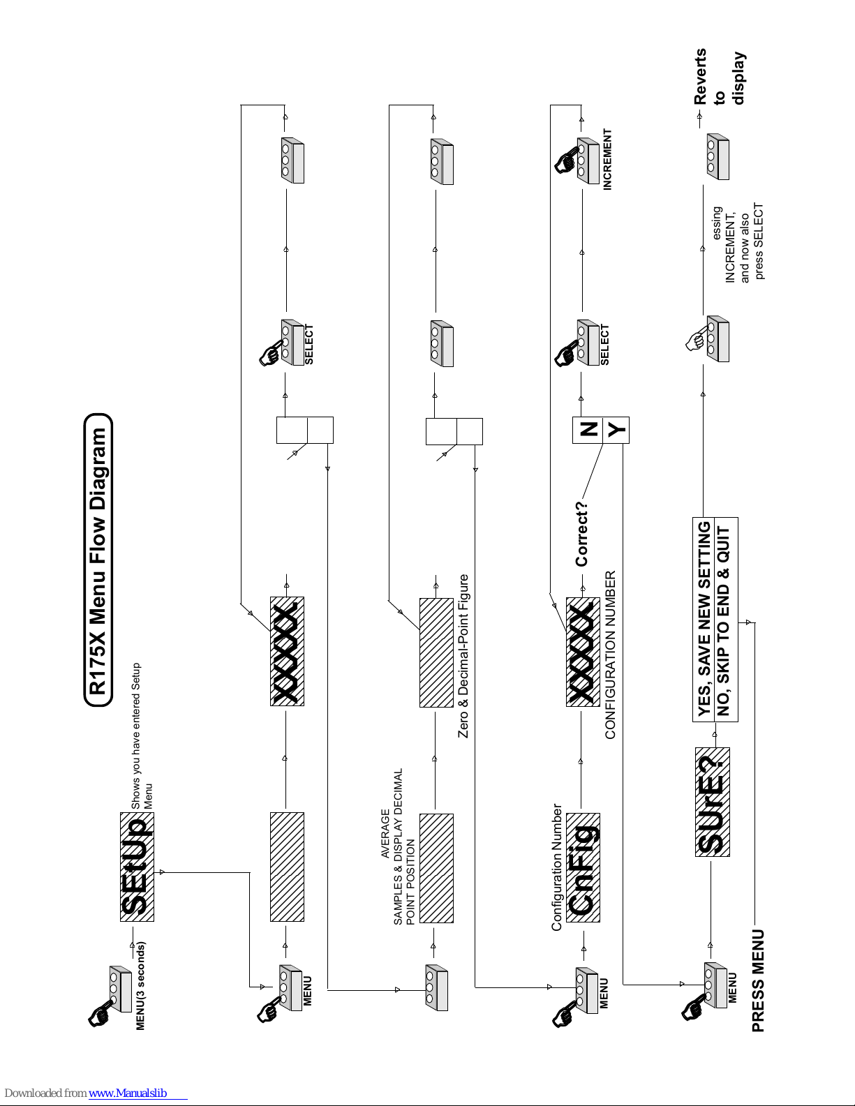
before carrying out a full calibration. The menu structure is described below, and is followed by a
flow diagram to add clarity.
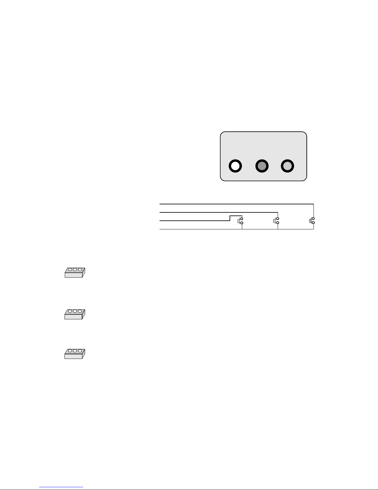
The flow diagram uses pictures of our Remote Programmer , consisting of three pushbuttons, arranged
as follows....
If you make up your own programmer, please
be sure to use good quality pushswitches, and
lay them out in the same order as shown here.
MENU SELECT INCR.
Yellow = Menu
Green = Select
Blue = Increment
Red = Common
FF
FF
F
MENU
SELECT
FF
FF
F
FF
FF
F
INCREMENT
Allows you to enter the programming menu and step down all the variable options
when in programming mode.
Allows you to select a digit within a variable, for alteration. The digit which can be
altered flashes. Each time you press 'SELECT' the flashing digit moves one place to the
right.
Allows you to increase the value of any flashing digit. Each press will increase the
value by 1 .
Page 10
10
4.6
The Programming Menu
As you enter the menu, prompts will appear on the display. Because they are formed with simple
7 segment displays, they do not appear to be familiar letter shapes, but are described in detail here.
SCALE This is the scale factor, which allows you to multiply or divide the input frequency (in Hz.)
by a constant. To divide, use a constant less than 1. The decimal point position in the scale factor
will determine the available display resolution, although the actual position of the decimal point in
display mode is set in the ZERO figure, below..
ZEro This is the number of readings the display will use in its moving average calculations. If you
set it to 5, for example, the next displayed value will be the average of the last 5 displayed values.
How often the display updates is determined by the Configuration number (see below) , and you
can choose between 3, 10 or 30 seconds.
So, let us assume you select a zero value of 3, and an update time of 30 seconds, the display will
update every 30 seconds, and show the average rate over the preceding 90 seconds.
You can set the decimal point position on the display in the zero number, athough you should be
aware that the decimal point is not influential in the zero number itself. So, a zero number of 000.05
will give 2 decimal places on the display, and the display will average over the last 5 readings ! The
resolution in the span figure will need to match that of the decimal point position. So if you want to
read the power line frequency in Hz. to 2 decimal places, showing the average of the last 20 readings,
set Scale to 001.00 and zero to 000.20
CnFIg is the Configuration number. This determines the display update rate, sets output data baudrate,
and determines the brightness setting. See below for Configuration number makeup..........
.
88888
Data O/P Baud Rate
300 baud = 4
1200 baud = 5
2400 baud = 6
9600 baud = 7
Always set
to zero
BRIGHTNESS ADJUSTMENT: Using SELECT, move to the right hand digit of the CnFG number. Press
SELECT once more, and the whole display will flash. now, each time you press INCREMENT the brightness will
move to a new level. Press MENU when you have selected the desired brightness
Ratemeter Mode
Set to 4 always
3 second update rate 5
10 Second update rate 6
30 second update rate 7
Page 11
11
12345
12345
12345
12345
12345
12345
12345
12345
12345
12345
12345
12345
12345
12345
12345
12345
12345
Shows you have entered Setup
Menu
FF
FF
F
MENU
SUrE?
YES, SAVE NEW SETTING
NO, SKIP TO END & QUIT
FF
FF
F
INCREMENT
AA
AA
A
INCREMENT
&
SELECT
Keep Pressing
INCREMENT,
and now also
press SELECT
PRESS MENU
R175X Menu Flow Diagram
MENU
FF
FF
F
X.X.X.X.X.
SELECT
FF
FF
F
FF
FF
F
INCREMENT
Scale Correct?
N
Y
Visible for 1 second
SCALE FACTOR
SCALE FACTOR
SCALE
FF
FF
F
12345
12345
12345
12345
12345
12345
12345
12345
12345
12345
12345
12345
12345
12345
12345
12345
ZErO
12345
12345
12345
12345
12345
12345
12345
12345
12345
12345
12345
12345
12345
12345
12345
12345
X.X.X.X.X.
SELECT
FF
FF
F
FF
FF
F
INCREMENT
Zero Correct?
N
Y
Visible for 1 second
MENU
NUMBER OF AVERAGE
SAMPLES & DISPLAY DECIMAL
POINT POSITION
MENU
12345
12345
12345
12345
12345
12345
12345
12345
12345
12345
12345
12345
12345
12345
12345
12345
CnFig
12345
12345
12345
12345
12345
12345
12345
12345
12345
12345
12345
12345
12345
12345
12345
12345
X.X.X.X.X.
SELECT
FF
FF
F
FF
FF
F
INCREMENT
Correct?
CONFIGURATION NUMBER
Configuration Number
FF
FF
F
SEtUp
Zero & Decimal-Point Figure
MENU(3 seconds)
N
Y
Revertstodisplay
FF
FF
F
Page 12
12
4.8 Application Example
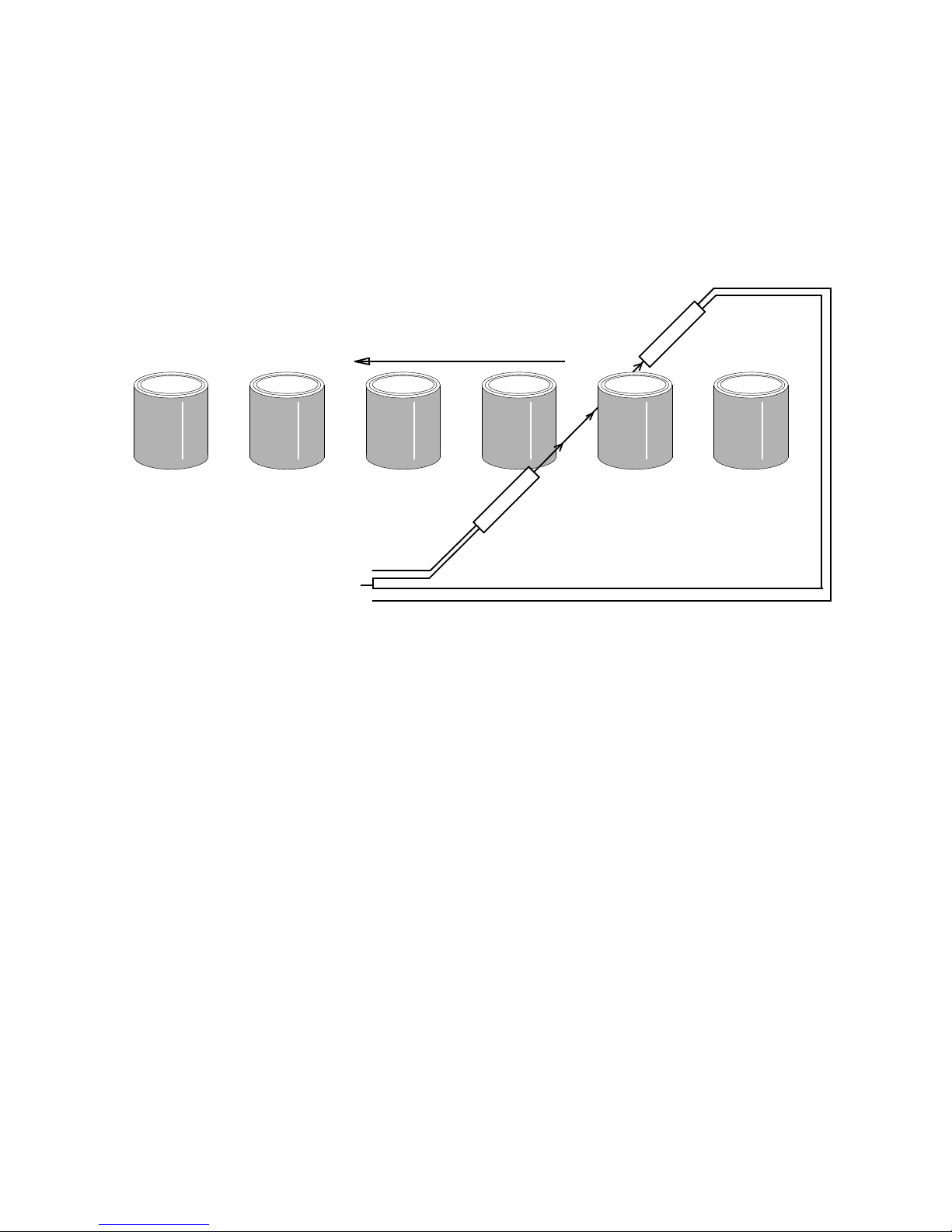
Below is a commonly encountered application, with details of suggested configurations, to aid in
commissioning your ratemeter.
Please feel free to call our Application Engineering Department for assistance with your particular
application, if you so wish, and we shall be pleased to help you.
A through-beam system is often the most effective method of sensing objects as they pass along a
conveyor. The system relies on the containers breaking a light beam as they pass along the
conveyor, and is quite insensitive to reflections, and does not rely on the surface colour or tint of
the objects passing by.
The transmitter and receiver are powered by the totaliser's excitation supply, and the receiver
provides and NPN or PNP output signal.
To operate reliably, the items on the conveyor must always be separated, to allow the beam to pass
between them individually. If the items have transparent areas, such as bottles or jars, avoid
passing the beam through the transparent area, as this can give false signals due to refractive
effects.
Fit the debounce jumpers, if the throughput is less than 10 items a second, so that maximum
immunity to electrical noise is available .
Use I/P B Control to freeze the sampling action during periods of down-time, such as lunch
breaks etc, so that the display shows true working-time average rates of production. When
enabled, the display will indicate the actual rate during the enabled period.
Remember to use screened cables for all signal lines, to avoid picking up noise from electrical
machinery.
Counting rate of objects passing along a conveyor.....
Excitation +
Common
Input A or B
Receiver
Transmitter
Page 13

13
5.0 INSTALLATION
If possible position the display away from heat and direct sunlight on the display face. The displays
should not be exposed to substances liable to damage uPVC, acrylic or glass.
If mounted outside, the display should be protected by a shroud to limit direct falls of rain, the
cooling effect of which can give rise to the display sucking in moisture.
DO NOT remove the cables supplied with the indicator, as these contain essential filter components.
You should extend cables with a junction box rather than remove and substitute cabling. Screening
must be used on your cables.
REMEMBER The signals you will be feeding to the displays are quite small in comparison to
some of the undesirable ‘noise’ generated by certain types of common electrical equipment. To
obtain the highest degree of accuracy and reliability from your indication equipment, we strongly
suggest that you....
DO use screened, twisted-pair cable to minimise the amount of noise being fed into the display.
DO NOT run signal cables adjacent to power/switching lines or near equipment liable to generate
large amounts of electrical noise, such as contactors, solenoids, fluorescent tubes, discharge lamps,
motor control equipment, etc. DO NOT earth the screens of signal , data or programmer cables, but
DO earth the screen on mains cables.
Page 14
14
12345678901234567890123456789012123456789012345
12345678901234567890123456789012123456789012345
12345678901234567890123456789012123456789012345
12345678901234567890123456789012123456789012345
12345678901234567890123456789012123456789012345
12345678901234567890123456789012123456789012345
12345678901234567890123456789012123456789012345
12345678901234567890123456789012123456789012345
12345678901234567890123456789012123456789012345
12345678901234567890123456789012123456789012345
12345678901234567890123456789012123456789012345
12345678901234567890123456789012123456789012345
12345678901234567890123456789012123456789012345
12345678901234567890123456789012123456789012345
12345678901234567890123456789012123456789012345
12345678901234567890123456789012123456789012345
12345678901234567890123456789012123456789012345
12345678901234567890123456789012123456789012345
12345678901234567890123456789012123456789012345
12345678901234567890123456789012123456789012345
12345678901234567890123456789012123456789012345
12345678901234567890123456789012123456789012345
12345678901234567890123456789012123456789012345
12345678901234567890123456789012123456789012345
12345678901234567890123456789012123456789012345
12345678901234567890123456789012123456789012345
12345678901234567890123456789012123456789012345
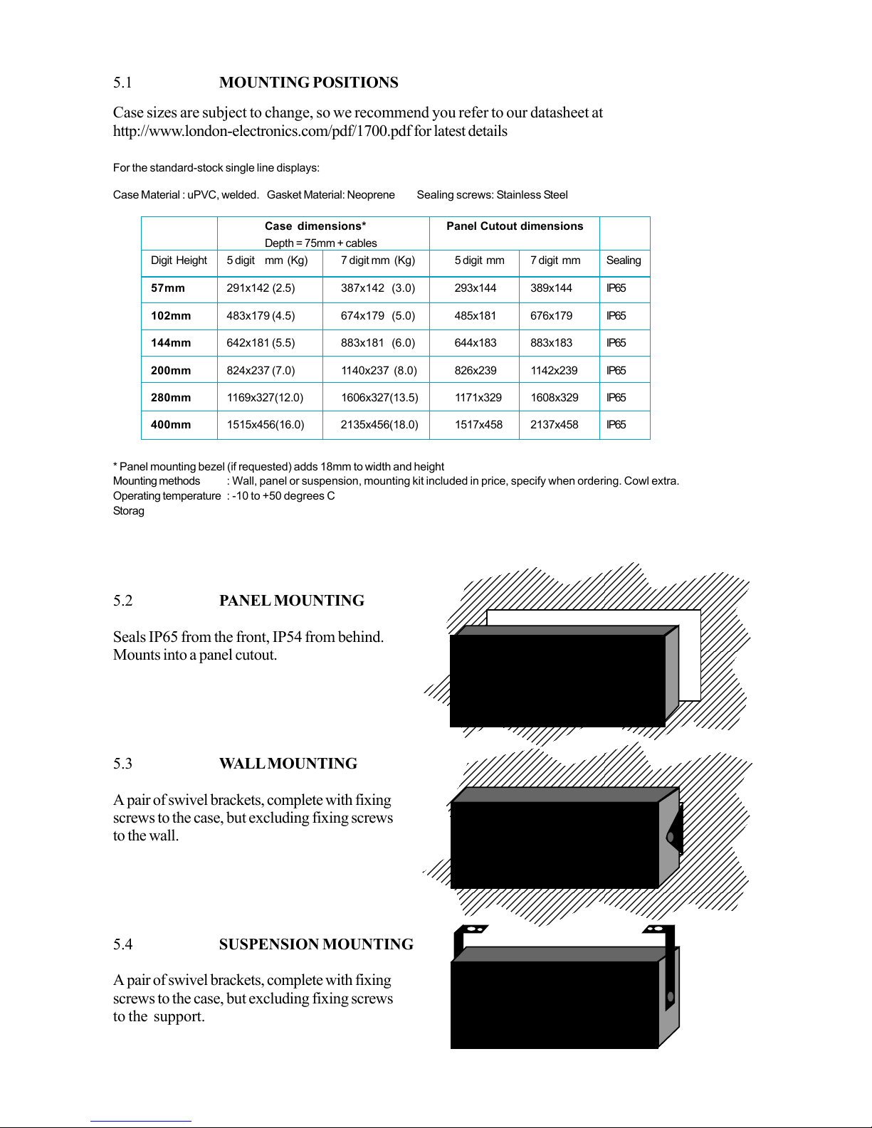
Case sizes are subject to change, so we recommend you refer to our datasheet at
http://www.london-electronics.com/pdf/1700.pdf for latest details
5.2 PANEL MOUNTING
Seals IP65 from the front, IP54 from behind.
Mounts into a panel cutout.
5.3 WALL MOUNTING
A pair of swivel brackets, complete with fixing
screws to the case, but excluding fixing screws
to the wall.
5.4 SUSPENSION MOUNTING
A pair of swivel brackets, complete with fixing
screws to the case, but excluding fixing screws
to the support.
5.1 MOUNTING POSITIONS
For the standard-stock single line displays:
Case Material : uPVC, welded. Gasket Material: Neoprene Sealing screws: Stainless Steel
Case dimensions* Panel Cutout dimensions
Depth = 75mm + cables
Digit Height 5 digit mm (Kg) 7 digit mm (Kg) 5 digit mm 7 digit mm Sealing
57mm 291x142 (2.5) 387x142 (3.0) 293x144 389x144 IP65
102mm 483x179 (4.5) 674x179 (5.0) 485x181 676x179 IP65
144mm 642x181 (5.5) 883x181 (6.0) 644x183 883x183 IP65
200mm 824x237 (7.0) 1140x237 (8.0) 826x239 1142x239 IP65
280mm 1169x327(12.0) 1606x327(13.5) 1171x329 1608x329 IP65
400mm 1515x456(16.0) 2135x456(18.0) 1517x458 2137x458 IP65
* Panel mounting bezel (if requested) adds 18mm to width and height
Mounting methods : Wall, panel or suspension, mounting kit included in price, specify when ordering. Cowl extra.
Operating temperature : -10 to +50 degrees C
Storage temperature : -40 to +60 degrees C
Humidity : 57-144mm types 100% (IP65), 200-400mm types 0-95% non-condensing (IP54)
General specifications for the 1700 series
88888
88888
88888
Page 15

15
N
6.0 TROUBLE SHOOTING AND MAINTENANCE
The Large displays have been designed to provide a long trouble-free life and require no routine maintenance.
An annual calibration check is recommended.
The front lens may be cleaned with a proprietary window cleaner, and the case may be hosed down, and
cleaned with a cloth dampened with mild detergent. Surface scratching can be polished out with a mildly
abrasive cleaner such as perspex cleaner.
The mains power supply is for 95 to 264 volts AC, so there is no risk of applying 240 volts to a 110 volt
unit. Filtering is incorporated on the mains input, to prevent damage due to short spikes on the mains.
Damage will occur if the unit is subject to 415 volt mains application.
Check wiring prior to powering the units!
Technical helpline 01767 626444 Please make a note of full model number, serial number and
configuration number before calling us. Please also read the manual before calling, and , if you find
any part unclear, or do not find the information you need, let us know. That way we can improve future
editions of the manual for you.
7.0 SAFETY CONSIDERATIONS
The 1700 series is protected in accordance with IEC Safety Class 1. The instruments are designed and
tested in accordance with IEC publication 348, ‘Safety Requirements for Electronic measuring apparatus’,
and are supplied in a safe condition.
Whenever protection is likely to have been impaired by damage, the equipment shall be made
inoperative and be secured against any intended operation.
Removal of the rear cover WILL EXPOSE LIVE PARTS. The equipment must be disconnected
from the supply before carrying out any adjustments, replacement, or repair with the case opened.
If any work is carried out with the equipment opened and powered, it shall only be carried out by a
skilled person who is aware of the hazard involved.
Mains connections:
The unit is operable as soon as the mains is applied, there is no mains switch.
The equipment must be connected to a protective earth. Any interruption of the earth conductor
inside or outside the equipment is likely to make the equipment dangerous.
The mains and signal leads should not be allowed to collect within the instrument; all excess lead
must be pulled out through the cable glands.
Note that capacitors inside the instrument may still be charged when the equipment has been
disconnected from the supply. Before carrying out any work inside the equipment, a period of one minute
should be allowed for capacitors to discharge; to discharge the mains filter capacitors, short together the
live and neutral mains wires.
Page 16

16
R F I
The equipment generates and uses radio frequency energy, but when properly installed as described,
complies with EN55022. The equipment is certified as meeting EN50081-1 and EN50082-1
Shielded cables MUST be used for all signal and data leads, but use of a shielded mains lead is not
required. The power earth wire must be bonded to a good earth, but DO NOT earth the signal, data or
remote programmer screens.
8.0 Warranty
London Electronics Ltd. warrants its products against defects in materials or workmanship for a period of
one year from the date of purchase.
In the event of a defect during the warranty period, the unit should be returned, freight( and all duties and
taxes ) prepaid by the Buyer to the authorised London Electronics Ltd. distributor from where the unit
was purchased. The Distributor, at its option, will repair or replace the defective unit. The unit will be
returned to the Buyer with freight charges prepaid by the distributor.
LIMITATION OF WARRANTY
The foregoing warranty shall not apply to defects resulting from:
1. Improper or inadequate maintenance by the
buyer.
2. Unauthorised modification or misuse.
3. Operation outside the environmental specification of the product.
4. Mishandling or abuse.
The warranty set forth above is exclusive and no other warranty, whether written or oral is expressed or
implied. London Electronics Ltd. specifically disclaims the implied warranties of merchantability and fitness
for a particular purpose.
EXCLUSIVE REMEDIES
The remedies provided herein are the buyer’s sole and exclusive remedies. In no event shall London
Electronics Ltd. be liable for direct, indirect, incidental or consequential damages (including loss of
profits) whether based on contract, tort or any other legal theory.
Page 17

17
Other London Products
We also design and manufacture a broad range of panel meters, controllers, transmitters, and other
types of Large Displays.
1/8 DIN Panel meters
Inputs accepted include...
Pulses- Totalisers & Quadrature
Pulses - Ratemeters
4-20mA
0-10V
Thermocouples
RTD's
AC Volts and Current
Resistance
Slidewire postion tranducers
Loadcells
Torque transducers
RS232, RS485, RS422, 20mA TTY
BCD
We also produce Custom special instruments, designed for you from your requirement specifications
Large Displays
Other forms of large displays manufactured by London Electronics Ltd. include.....
Serial Input remote displays
Ratemeters
Proces Indicators
Weight Indicators
Draw Meters
Rate of Change indicators
Clocks
For a Full Catalogue and PriceList, please call us on 01767 626444, and we will despatch details
immediately.
9.0
Page 18

18
9.0
AND FINALLY...
We really would appreciate receiving any comments you may wish to make after receiving your
LONDON ELECTRONICS LTD. Large displays.
In particular , if you experienced any difficulties during any stage of your purchase, your comments will enable us to serve you better in the future.
Similarly, if there are any additional features you feel you would benefit from by having them
included in our range of equipment , please let us know and we will give your suggestions
serious consideration.
Please complete the section below and return it to us as soon as possible so that changes can be
made without delay.
Thank you for choosing products from LONDON ELECTRONICS LTD. !
NAME_____________________________JOB FUNCTION____________________________
COMPANY____________________________________________________________________
ADDRESS____________________________________________________________________
__________________________________________________________________________
__________________________________________________________________________
POST CODE _______________________TEL. NO._________________________________
MODEL NUMBER_________________________SERIAL NUMBER____________________
BRIEF APPLICATION DESCRIPTION_____________________________________________
_____________________________________________________________________________
_____________________________________________________________________________
COMMENTS__________________________________________________________________
_____________________________________________________________________________
_____________________________________________________________________________
SIGNED______________________________ DATE__________________________________
Page 19

19
NOTES
Page 20

20
Declaration of Conformity
Conditions
The meters are permitted a worst case error of 1% of A/D range during electro-magnetic disturbance,
and must recover automatically when disturbance ceases without the need for human intervention,
such as resetting, power-down etc.
The meters covered by this certificate must be installed in adherence to the following conditions :-
Signal cabling shall be routed separately to power carrying cabling (includes relay output wiring)
All signal cabling shall be screened. The screen shall only be terminated to the power earth terminal
This certificate applies only to meters carrying Serial Numbers 601001 or higher.
Signed as true and correct, for and on behalf of London Electronics Ltd.
J.R. Lees
Director
Declaration Number : EMC1700 Iss. 3
Issue Date : 21 April 1997
Products Covered : 1700 Series Large Displays
Title : Large Process, Serial
Rate & Totalising Displays
This is to confirm that the Products covered by this declaration have been designed and manufactured
to meet the following specifications :
EN55022:1987 Conducted Emissions: Class B
EN55022:1987 Radiated Emissions : Class B
IEC801-2:1984 Electro-Static Discharge Immunity: 8kV Air
IEC801-3:1984 Radiated ElectroMagnetic field Immunity: 3V/m
IEC801-4:1988 Fast Transient Immunity : AC 1kV, cable 0.5kV
Thus the products conform with the applicable sections of the following standards:
EN50081-1:1992 (normative)
EN50082-1:1992 (normative)
and comply with the requirements of Council Directive 89/336/EEC relating to Electro-Magnetic
Compatibility.
To confirm compliance, representative models within the range have been independently tested and
certified by MARCONI INSTRUMENTS EMC Department.
MARCONI CERTIFICATE # : TC96/029C
MARCONI CERTIFICATE Issue #: 1
MARCONI Certificate Issue Date : 14 February 1996
 Loading...