

Page 1
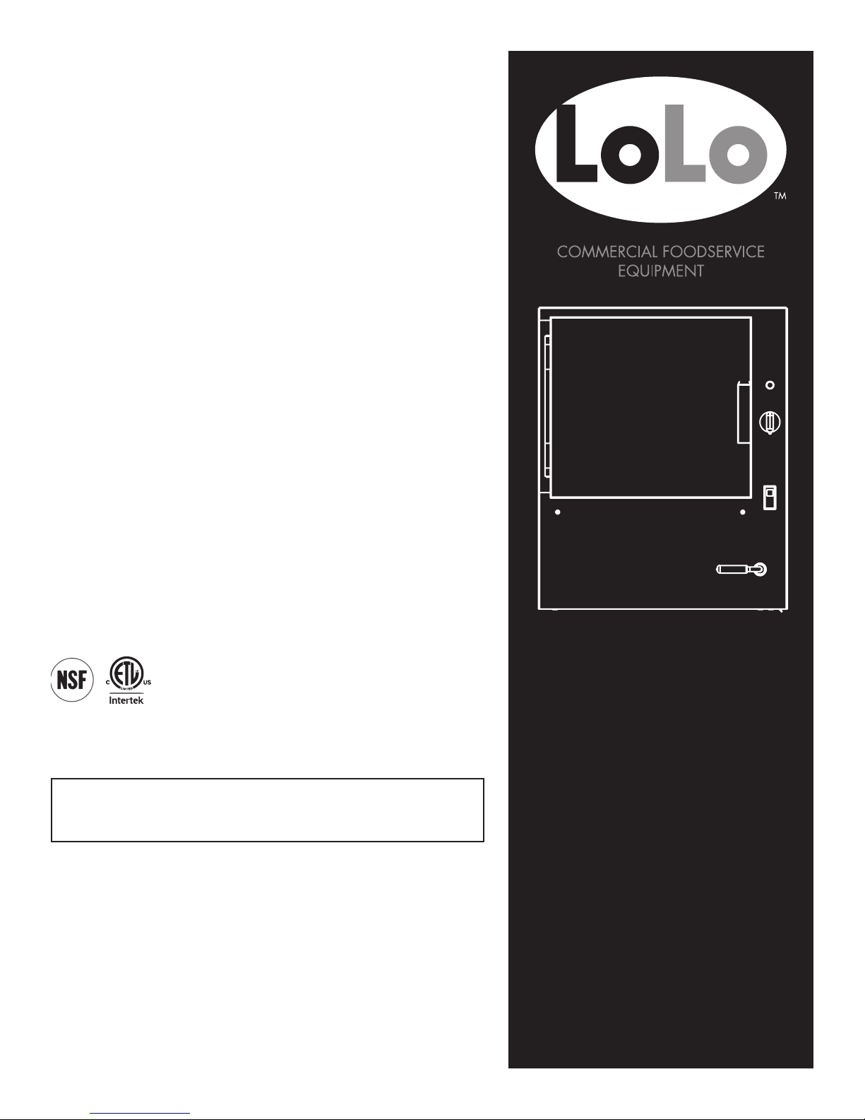
OPERATOR MANUAL
IMPORTANT INFORMATION, KEEP FOR OPERATOR
This manual provides information for:
Steamer
MODEL: ST-4E/6E
THIS MANUAL MUST BE RETAINED FOR FUTURE REFERENCE.
READ, UNDERSTAND AND FOLLOW THE INSTRUCTIONS AND
WARNINGS CONTAINED IN THIS MANUAL.
FOR YOUR SAFETY
Do not store or use gasoline or other ammable vapors
and liquids in the vicinity of this or any other appliance.
NOTIFY CARRIER OF DAMAGE AT ONCE
It is the responsibility of the consignee to inspect the container upon receipt and
to determine the possibility of any damage, including concealed damage. LoLo
Commercial Foodservice Equipment suggests that if you are suspicious of damage to make a notation on the delivery receipt. It will be the responsibility of the
consignee to le a claim with the carrier. We recommend that you do so at once.
Manufacturer’s Service/Questions 877-246-5656
Information contained in this document is known to be current and accurate at the time of
printing/creation. LoLo Commercial Foodservice Equipment recommends referencing our product
line website, www.getLoLo.com, for current product information and specifications.
PART NUMBER 162326 REV E (12/14)
Page 2

IMPORTANT - READ FIRST - IMPORTANT
WARNING: THE UNIT MUST BE INSTALLED BY PERSONNEL QUALIFIED TO WORK WITH ELECTRICITY/GAS AND
PLUMBING. IMPROPER INSTALLATION CAN CAUSE INJURY TO PERSONNEL AND/OR DAMAGE TO
THE EQUIPMENT. THE UNIT MUST BE INSTALLED IN ACCORDANCE WITH APPLICABLE CODES.
CAUTION: SHIPPING STRAPS ARE UNDER TENSION AND CAN SNAP BACK WHEN CUT.
CAUTION: DO NOT INSTALL THE UNIT IN ANY WAY WHICH WILL BLOCK THE REAR VENTS, OR WITHIN 2
INCHES OF A HEAT SOURCE SUCH AS A BRAISING PAN, DEEP FRYER, CHAR BROILER OR
KETTLE.
CAUTION: LEVEL THE UNIT LEFT-TO-RIGHT, AND PITCH IT SLIGHTLY TO THE FRONT, TO AVOID
DRAINAGE PROBLEMS.
WARNING: FOLLOW THE WIRING DIAGRAM EXACTLY WHEN CONNECTING A UNIT TO AVOID
DAMAGE OR INJURY. WIRING DIAGRAM IS LOCATED ON THE INSIDE OF THE RIGHT PANEL.
CAUTION: DO NOT USE PLASTIC PIPE. DRAIN MUST BE RATED FOR BOILING WATER.
CAUTION: DO NOT CONNECT THE DRAIN DIRECTLY TO A BUILDING DRAIN.
CAUTION: BLOCKING THE DRAIN IS HAZARDOUS.
IMPORTANT: IMPROPER DRAIN CONNECTION WILL VOID WARRANTY.
CAUTION: WHEN YOU OPEN THE DOOR, STAY AWAY FROM STEAM COMING OUT OF THE UNIT.
STEAM CAN CAUSE BURNS.
WARNING: BEFORE CLEANING THE OUTSIDE OF THE STEAMER, DISCONNECT THE POWER SUPPLY.
KEEP WATER AND CLEANING SOLUTIONS OUT OF CONTROLS AND COMPONENTS.
NEVER HOSE OR STEAM CLEAN ANY PART OF THE UNIT.
CAUTION: ALLOW COOKING CHAMBER TO COOL COMPLETELY BEFORE CLEANING.
CAUTION: USE MILD CLEANING AGENTS ONLY. CAREFULLY READ THE WARNINGS AND FOLLOW
THE DIRECTIONS ON THE LABEL OF EACH CLEANING AGENT. USE SAFETY GLASSES
AND RUBBER GLOVES AS RECOMMENDED BY CLEANING AGENT MANUFACTURER.
CAUTION: DO NOT OPERATE THE UNIT UNLESS THE REMOVABLE RIGHT SIDE PANEL HAS BEEN
RETURNED TO ITS PROPER LOCATION.
IMPORTANT: DO NOT USE A CLEANING AGENT THAT CONTAINS ANY SULFURIC ACID, OR ANY
CHLORIDE, INCLUDING HYDROCHLORIC ACID. IF THE CHLORIDE CONTENT OF ANY
PRODUCT IS UNCLEAR, CONSULT THE MANUFACTURER. DO NOT USE A CLEANING OR
DELIMING AGENT THAT CONTAINS MORE THAN 30% PHOSPHORIC ACID.
IMPORTANT: DO NOT USE ANY DEGREASER THAT CONTAINS POTASSIUM HYDROXIDE OR SODIUM
HYDROXIDE OR THAT IS ALKALINE.
IMPORTANT: USE OF ANY REPLACEMENT PARTS OTHER THAN THOSE SUPPLIED BY LOLO COMMERCIAL
FOODSERVICE EQUIPMENT OR THEIR AUTHORIZED DISTRIBUTOR VOIDS ALL WARRANTIES AND
CAN RESULT IN BODILY INJURY TO THE OPERATOR AND DAMAGE THE EQUIPMENT. SERVICE BY
OTHER THAN FACTORY-AUTHORIZED PERSONNEL WILL VOID ALL WARRANTIES.
WARNING: HIGH VOLTAGE EXISTS INSIDE CONTROL COMPARTMENTS. DISCONNECT FROM BRANCH
CIRCUIT BEFORE SERVICING. FAILURE TO DO SO CAN RESULT IN INJURY OR DEATH.
2 OM-ST-4E/6E
Page 3
IMPORTANT - READ FIRST - IMPORTANT
SAFETY PRECAUTIONS
Before installing and operating this equipment be sure everyone involved in its
operation are fully trained and are aware of all precautions. Accidents and problems
can result from a failure to follow fundamental procedures and precautions.
The following words and symbols, found in this manual, alert you to potential hazards
to the operator, service personnel or the equipment. The words are defined as follows:
DANGER: This symbol warns of an imminent hazard which will result in serious
injury or death.
WARNING: This symbol refers to a potential hazard or unsafe practice, which could
result in serious injury or death.
CAUTION: This symbol refers to a potential hazard or unsafe practice, which could
result in minor or moderate injury, or product or property damage.
NOTICE: This symbol refers to information that needs special attention or must be
fully understood even though not dangerous.
This product is intended for commercial use only. Not for household use.
Local codes regarding installation vary greatly from one area to another.
The National Fire Protection Association, Inc., states in its NFPA96 latest edition that
local codes are “Authority Having Jurisdiction” when it comes to requirements for
installation of equipment. Therefore, installation should comply with all local codes.
IMPORTANT FOR FUTURE REFERENCE
Please record this information and retain this manual for the life of the equipment. For Warranty Service
and/or parts, this information is required.
Model Number Serial Number Date Purchased
OM-ST-4E/6E 3
Page 4

Table of Contents
Important Warnings & Safety Precautions ........................................... 2-3
References.............................................................................................. 4
Equipment Description........................................................................... 5
Inspect for Shipping Damage .................................................................. 6
Uncrating ................................................................................................ 6
Installation Instructions ....................................................................... 7-9
Initial Start-Up...................................................................................... 10
Operation – General Steamer Use ....................................... ..........11-12
Cleaning..............................................................................13-14
Maintenance ..................................................................................... ...15
User Troubleshooting Guide.................................................................. 16
Parts Lists & Diagrams ................................................................... 17-24
Wiring Diagram.................................................................................... 25
References
NATIONAL FIRE PROTECTION ASSOCIATION
60 Batterymarch Park
Quincy, Massachusetts 02269
NFPA/70
The National Electrical Code
NSF INTERNATIONAL
789 N. Dixboro Rd.
Ann Arbor, Michigan 48113-0140
INTERTEK (ETL)
1950 Evergreen Blvd, Suite 100
Duluth, GA 30096
4 OM-ST-4E/6E
Page 5
Equipment Description
Congratulations on your purchase of LoLo commercial cooking
equipment. LoLo takes pride in the design and quality of our products.
When used as intended and with proper care and maintenance, you will
experience years of reliable operation from this equipment. To ensure
best results, it is important that you read and follow the instructions in
this manual carefully.
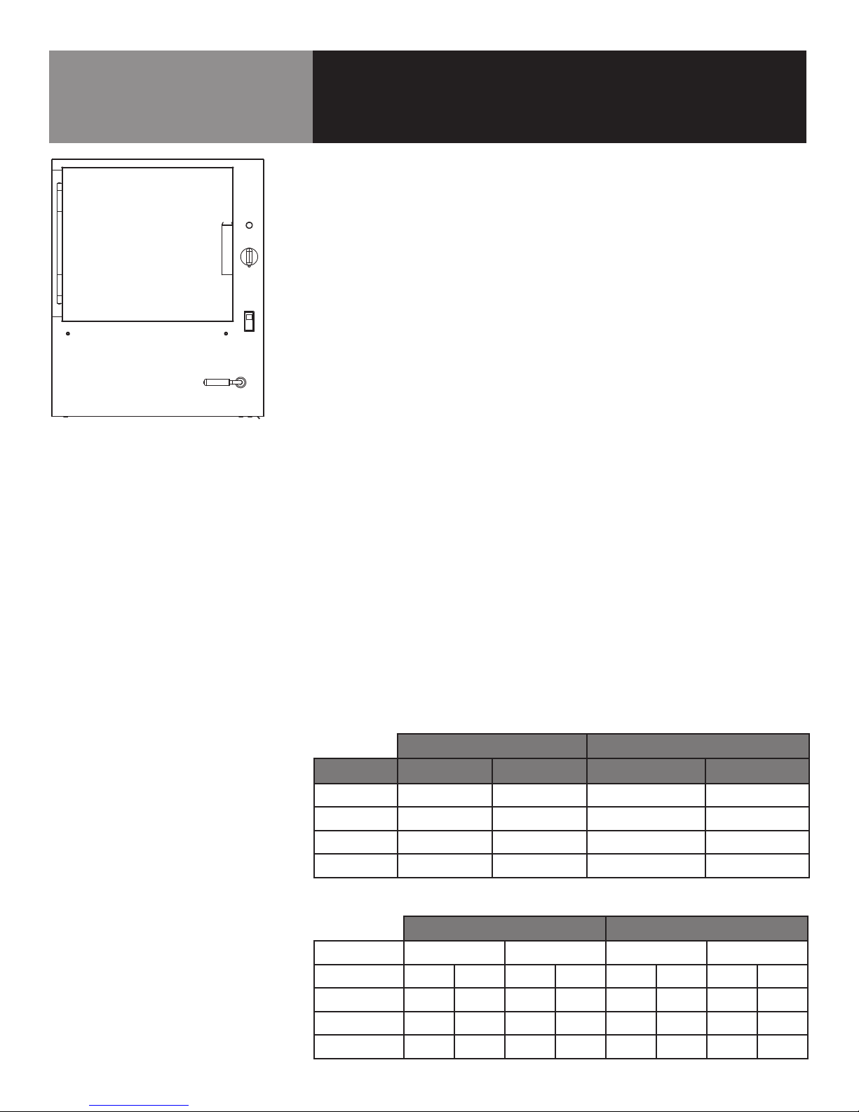
LoLo ST-4E and ST-6E electric-heated pressureless and boilerless steamers are
designed to be simple to use, steam foods quickly and provide years of trouble-free
service. These steamers have a boilerless steam system that uses electric heating
elements that are mounted to the bottom of the cooking compartment, to heat clean
water inside that compartment. It is provided with an auto-fill water system with simple
high and low water level sensors; and a free-venting drain, which allows cooking
compartment access at any time.
LoLo Steamers come standard with a rugged solid door with a continuous piano hinge and
easy-open hands-free latch; and a removable condensate drip pan mounted below the door.
Simple operating controls include: a Power-ON/OFF switch; a Steam Level Switch
that allows the operator to select: Hi Performance mode for a la carte cooking, Energy
Saving mode for batch cooking or Standby mode for energy savings and instant
Ready status; a (steamer) READY light; and 60-minute mechanical timer that initiates
steaming, with a continuous-steaming non-timed (ON) position.
A simple valve/handle drains water from the reservoir at day’s end. Hidden door-OPEN
steam cutoff switch, upper and lower water fill-level fill valves and a high-limit switch
ensure safe and trouble-free operation.
The ST-4E model will hold up to four 2-1/2” deep steamer pans or two 4”deep pans.
The ST-6E model will hold up to six 2-1/2” deep steamer pans or three 4” deep pans.
KEY UNIT DIMENSIONS
US/metric
Dimension Model ST-4E Model ST-6E
Unit Width
Height
Unit Depth
Ship. Weight
20.4” 518 mm 20.4” 518 mm
24.6” 625 mm 31.5” 800 mm
27.9” 709 mm 27.9” 709 mm
220 lbs 100 kg 275 lbs 125 kg
Water & Drain Requirements
Water connection via:
Min. Water Pressure
Max. Water Pressure
Volume Minimum
Drain connection via
3/4" NH (hose)
30 PSI
60 PSI
2.0 gallon/min.
1.5” (38 mm) ID
ELECTRIC REQUIREMENTS
ST-4E Models ST-6E Models
*Voltage
kW
*Phase
Hz/Cycles
Amps
* Ships dual voltage, field convertible to single phase by qualified electrician.
208 / 240* 208 / 240* 208 / 240* 208 / 240*
9 12 9 12 10.8 14.4 10.8 14.4
1 1 3 3 1 1 3 3
60 60 60 60 60 60 60 60
43.3 50 25 28.9 52 60 30 34.7
OM-ST-4E/6E 5
Page 6
Inspect for Shipping Damage
All containers should be examined for damage before and during unloading. The
freight carrier has assumed responsibility for its safe transit and delivery. If the
equipment is received damaged, either apparent or concealed, a claim must be made
with the delivering carrier.
1. Apparent damage or loss must be noted on the freight bill at the time of
delivery. It must then be signed by the carrier representative (driver). If this is
not done, the carrier may reject the claim. The carrier can supply the necessary
claim forms.
2. Concealed damage or loss if not apparent until after the equipment is uncrated,
can also be claimed. However, a request for inspection must be made to the
carrier within 15 days. The carrier should arrange an inspection. Be certain to
retain all contents and packaging material.
USE CAUTION WHEN UNCRATING LOLO
EQUIPMENT. METAL AND PLASTIC BANDING
IS UNDER TENSION AND CAN SNAP BACK
WHEN CUT. WOOD PALLETS OR SKIDS CAN
CONTAIN SPLINTERS AND NAILS. SHIPPING
CARTONS CAN CONTAIN LARGE STAPLES.
WEAR GLOVES AND PROTECTIVE EYEWEAR
WHEN OPENING, MOVING AND DISPOSING
OF SHIPPING CONTAINERS.
THE LOLO STEAMERS ARE HEAVY, WEIGHING
220 OR 275 POUNDS (100-125 KG),
DEPENDING ON MODEL. OBTAIN HELP OR
USE APPROPRIATE MATERIALS-HANDLING
EQUIPMENT; AND USE CAUTION WHEN
REMOVING THE STEAMER FROM THE WOOD
PALLET.
Uncrating
1. Cut strapping or banding that closes the top of the cardboard shipping carton
and secures it to the wood pallet.
2. Lift carton straight up and off the steamer. Obtain help if needed.
3. Remove any Styrofoam blocking or wood bracing that protects unit from
shipping damage.
4. Cut strapping or banding that secures steamer to the wood pallet or skid.
5. Obtain help as needed, or use materials handling equipment, to lift the steamer
off and clear of wood pallet.
6. Remove any banding or tape used to secure the compartment door.
7. Pull off any grey/white plastic from stainless steel surfaces. This adhesivebacked plastic protects surfaces for scratches during fabrication and shipping.
8. Dispose of cardboard carton, Styrofoam and wood pallet/skid by recycling.
6 OM-ST-4E/6E
Page 7
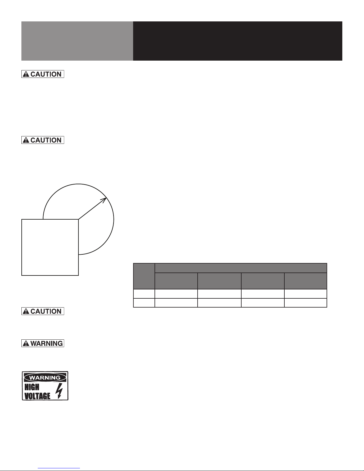
THE UNIT MUST BE INSTALLED BY PERSONNEL
WHO ARE QUALIFIED TO WORK WITH
ELECTRICITY AND PLUMBING. IMPROPER
INSTALLATION CAN CAUSE INJURY TO
PERSONNEL AND/OR DAMAGE TO THE
EQUIPMENT. THE UNIT MUST BE INSTALLED IN
ACCORDANCE WITH APPLICABLE CODES.
DO NOT INSTALL THE UNIT WITH THE REAR
VENTS BLOCKED OR WITHIN 2 INCHES OF A
HEAT SOURCE SUCH AS A BRAISING PAN, DEEP
FAT FRYER, CHARBROILER OR KETTLE.
18 -inch
radius
mm
457
STEAM
FREE
ZONE
TOP VIEW
Installation Instructions
Install the steamers in a well-ventilated room positioned under a Type I or Type II
ventilation hood. Consult and follow local codes for use of an electric heated steamer
(which doesn’t produce smoke, grease laden vapors or gas combustion byproducts)
without a ventilation hood.
MINIMUM CLEARANCES
LoLo steamer requires the following minimum clearances to any surface, combustible
or non-combustible:
• 2” (51 mm) on both sides
• 6” (152 mm) in rear/back
Steam Free Zone: The steamer can be damaged by steam from external sources. Do
not install the steamer over a steam venting drain. Ensure that steam is not present
in an area bounded by the footprint of the steamer and a circle 18 inches in radius
around the right rear corner of the steamer (See Diagram 7-1 at left).
ELECTRICAL SUPPLY CONNECTION
Provide service per local codes and/or the National Electrical Code should be observed
in accordance with ANSI/NFPA 70. AN ELECTRICAL GROUND IS REQUIRED. The
wiring diagram is located in the service compartment and in this manual. In Canada,
provide electrical service in accordance with the Canadian Electrical Code, CSA C22.2
Part 1 and/or local codes.
Electric current and power demands for each unit are as listed below.
FRONT OF UNIT
Diagram 7-1
EACH UNIT MUST HAVE A SEPARATE GROUND
WIRE FOR SAFE OPERATION.
TO AVOID DAMAGE OR PERSONAL INJURY,
FOLLOW THE WIRING DIAGRAM EXACTLY.
Model Rated Current Demand Per Cavity
208/3 -
AMP/KW
ST-4E 25.0/9 43.3/9 50/12 28.8/12
ST-6E 30/10.8 52/10.8 60/14 36.6/14
208/1 -
AMP/KW
240/1 -
AMP/KW
208/3 -
AMP/KW
1. Panel Removal - Right Side
Open the wiring and control panel by removing the screws from the right
side panel. Remove and set aside. Save all screws.
2. Supply Voltage
The unit must be operated at the rated name plate voltage. The name plate
sticker can be found on the rear of the unit.
3. Phase Selection
Refer to steamer wiring diagram and element wiring on page 25 for wiring
information.
4. Terminal Block
The terminal block for incoming power is located at the back of the
OM-ST-4E/6E 7
Page 8
THE UNIT MUST BE INSTALLED BY PERSONNEL
WHO ARE QUALIFIED TO WORK WITH
ELECTRICITY AND PLUMBING. IMPROPER
INSTALLATION CAN CAUSE INJURY TO
PERSONNEL AND/OR DAMAGE TO THE
EQUIPMENT. THE UNIT MUST BE INSTALLED IN
ACCORDANCE WITH APPLICABLE CODES.
Installation Instructions
control compartment. The ground terminal is located in the wiring
compartment near the terminal block.
5. Supply Wire
The equipment grounding wire must comply with the National Electrical Code
(NEC) requirements. The wiring diagram on the inside of the unit’s right side
service access panel gives directions for proper connection to the terminal
block. The specified wire must be used or the unit will not meet Underwriters
Laboratories and NEC requirements. The electric hole is sized for a one-inch
conduit fitting.
DO NOT INSTALL THE UNIT WITH THE REAR
VENTS BLOCKED OR WITHIN 2 INCHES OF A
HEAT SOURCE SUCH AS A BRAISING PAN, DEEP
FAT FRYER, CHARBROILER OR KETTLE.
6. Branch Circuit Protection
Each LoLo steamer, including individual stand-stacked units, should have its
own branch circuit protection and ground wire.
WATER CONNECTION
Install a check valve to prevent back flow into the incoming cold water line, as
required by local plumbing codes. Water pressure in the line should be between 30
and 60 PSI. If pressure is above 60 PSI, a pressure regulator should be installed. These
pressures must provide a delivery rate of 2 gallons per minute for proper steamer
operation.
A 3/4 inch female NH connector (garden hose type) is used to attach the water supply
to the inlet valve. The minimum inside diameter of the water feed line is 1/2 inch. Use
a rubber washer in the hose connection. Do not allow the connection to leak, no matter
how slowly. IMPORTANT: Do not over-tighten hose connections.
Installation of this equipment must comply with the basic plumbing code of the
Building Officials and Code Administrators International, Inc. (BOCA) and the Food
Service Sanitation Manual of the Food and Drug Administration (FDA).
8 OM-ST-4E/6E
Page 9
Installation Instructions
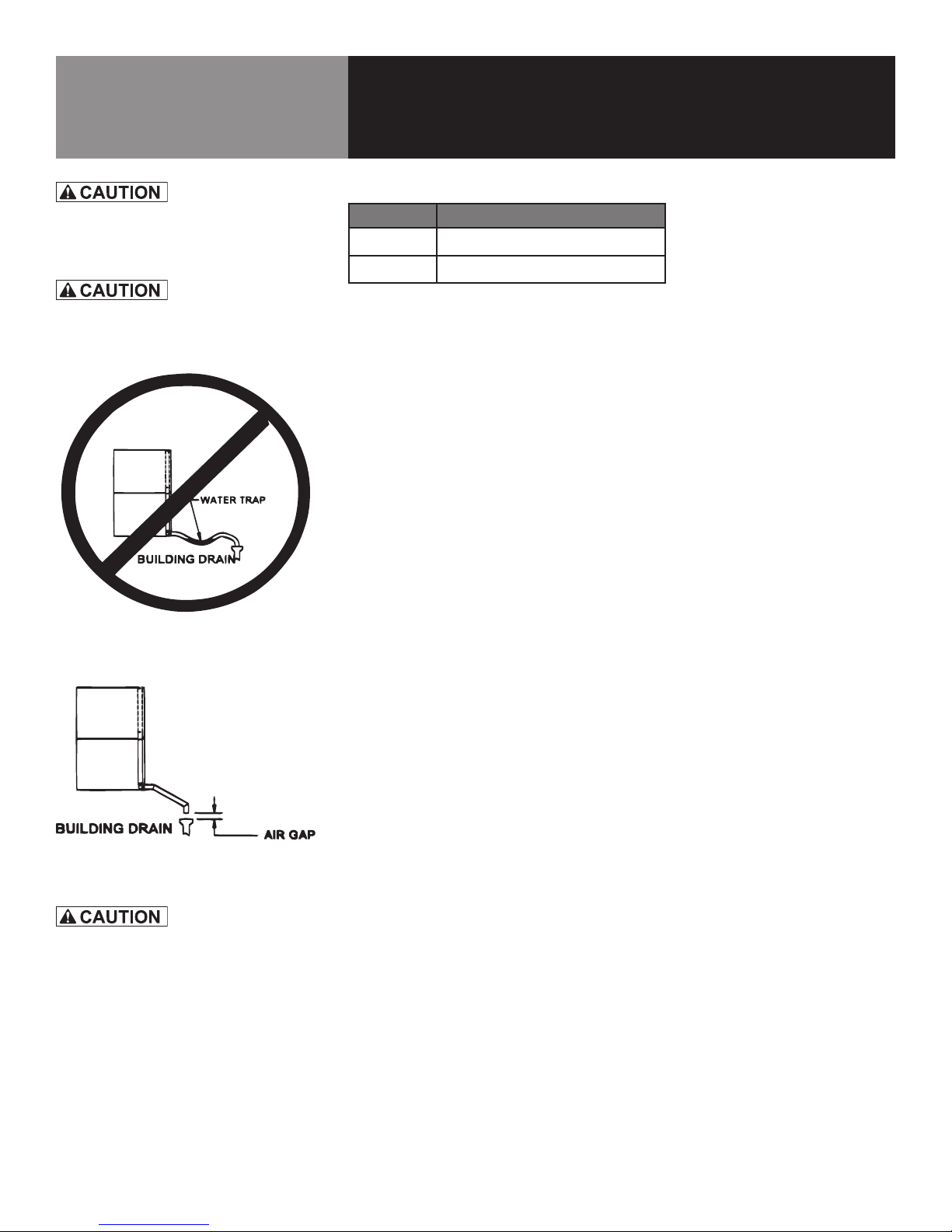
DO NOT CONNECT THE DRAIN DIRECTLY
TO A BUILDING DRAIN. BLOCKING THE DRAIN
IS HAZARDOUS.
DO NOT USE PLASTIC PIPE. DRAIN MUST BE
RATED FOR BOILING WATER.
Diagram 9-1
Improper Drain Line Connection
DRAIN CONNECTION
Model Drain ID Hose Size Required
ST-4E
ST-6E
1.5”
1.5”
Level the steamer left-to-right, and pitch it slightly to the front (maximum 1/4 inch) by
adjusting the optional legs or the bullet feet on the optional stand.
There must be a free air gap between the end of the drain hose and the building drain.
The free air gap should be as close as possible to the unit drain. There must also be
no other elbows or other restrictions between the unit drain and the free air gap.
Install the drain line with a constant downward pitch (see Diagram 9-1 and 9-2 at
left). IMPORTANT: Do not allow water traps in the line. A trap can cause pressure
build-up in the cooking compartment, which may cause the door gasket to leak.
For a proper drain line connection, the drain line must have a constant downward
pitch of at least 1/4” per foot. Observe local code regarding air gap spacing and drain
connections.
COUNTER-MOUNTED UNITS
This section is applicable when the steamer will be flush-mounted to a counter. All
four edges of the bottom of the steamer must be sealed with RTV silicone sealant to
the counter if optional 4 inch legs are not used. Counter must be made of a noncombustible material such as metal or tile.
Diagram 9-2
DO NOT PLACE A LOLO STEAMER ON
A CONVENTIONAL UNDERCOUNTER
REFRIGERATOR. THEY ARE NOT DESIGNED
TO SUPPORT THE WEIGHT OR INSULATED
AGAINST THE HEAT PRODUCED BY THE
STEAMER. FAILURE TO USE A PURPOSEBUILT REFRIGERATED EQUIPMENT STAND
COULD RESULT IN REFRIGERATOR FAILURE,
UNSAFE OR SPOILED FOOD AND EVEN
MELTED PLASTIC COMPONENTS IN THE
REFRIGERATOR.
STAND STACKED UNITS
This section is only applicable if you are installing two steamers on the optional support stand. The steamers are positioned on the top and bottom shelf that are standard
with LoLo Steamer Stands.
1. Water Connections
Separate water supply connections must be provided for each unit. At each wa-
ter inlet valve a ¾” NH connection (garden hose type) is used to supply water at
the pressure and delivery rate specified on page 5 and 8.
2. Electrical Supply Connections
Separate electrical connections are required for each steamer on the stand.
NOTE: Each steamer must have its own branch circuit protection.
3. Drain Connections
Both steamers must be leveled left-to-right; and pitched to the front (maximum
of ¼”) by adjusting the bullet feet or casters on the steamer stand. Make sure
both steamer drain connections are free-venting and slope continuously to the
floor drain.
REFRIGERATED STAND MOUNTED STEAMERS
IMPORTANT: Do not mount a LoLo Steamer on a conventional undercounter refrigera-
tor. Steamers must be placed on a refrigerated equipment stand, such as the LoLo
LRES Series, which are specifically designed to support the weight of heavy cooking
equipment; and heavily insulated to resist the heat generated by a working steamer.
OM-ST-4E/6E 9
Page 10
Initial Start-Up
WHEN YOU OPEN THE DOOR, STAY AWAY
FROM STEAM COMING OUT OF THE UNIT.
STEAM CAN CAUSE BURNS.
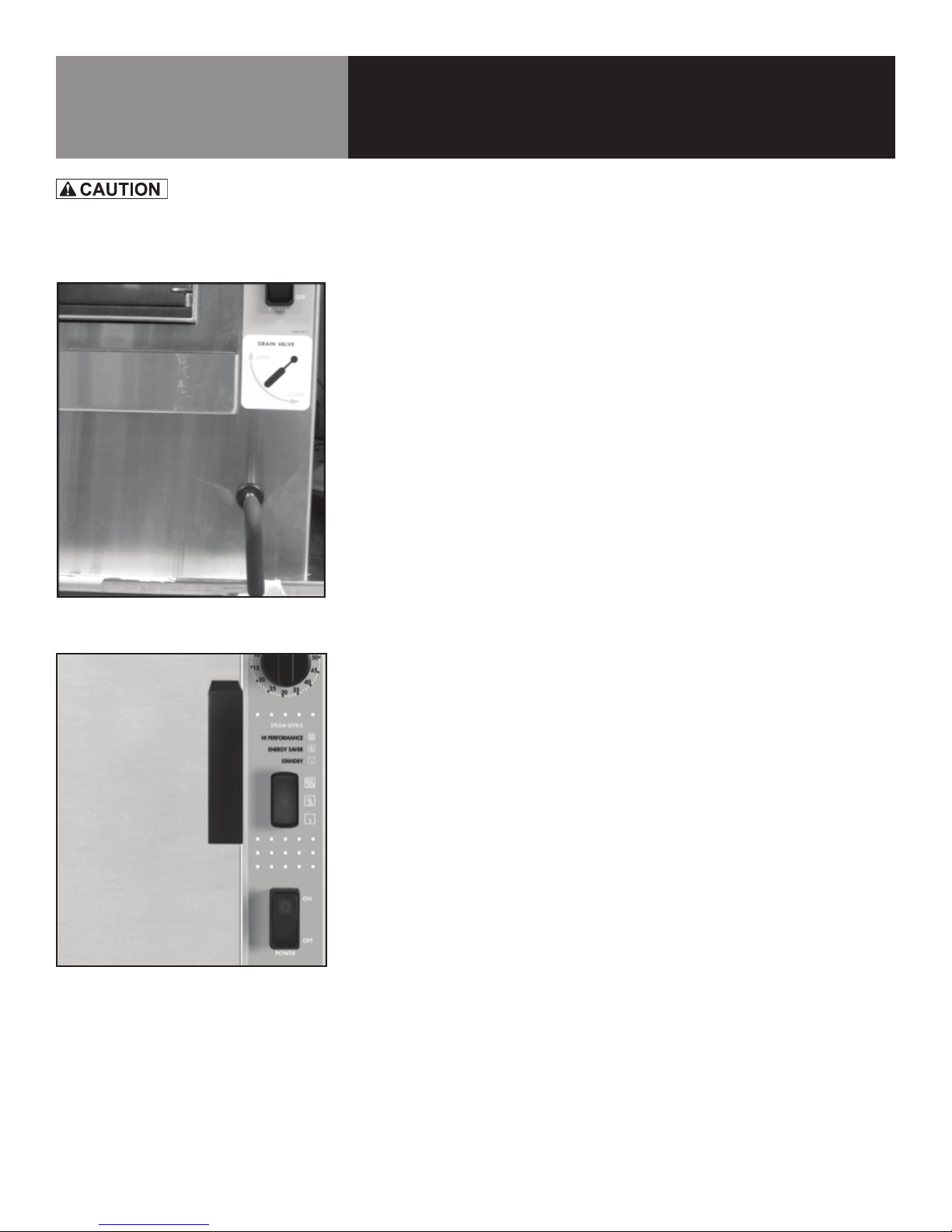
Photo 10-1
After the LoLo steamer has been installed, test it to ensure that the unit is operating
correctly.
1. Remove all literature and packing materials from the interior of the unit.
2. Make sure the water supply line is open and the drain valve handle is in the
closed position (6:00 o’clock). (See Photo 10-1)
3. Turn on electrical service to the unit. The steamer will not operate without electrical power. IMPORTANT: Do not attempt to operate the unit during a power
failure.
NOTE: The door MUST be closed for the elements to operate.
4. To turn unit on, toggle POWER ON/OFF switch to the ON position and rotate
timer knob to ON position. The green light on the switch will come on.
NOTE: For normal operation, the POWER ON/OFF switch may be left in the ON
position. Use the timer knob to turn unit steaming ON and OFF during the day.
5. Make sure three position STEAM LEVEL switch is in HIGH PERFORMANCE or
ENERGY SAVER position.
6. When the steam generating reservoir has filled with water, the heaters will
begin heating only when the timer is in the ON or TIMING position. Within
15 minutes or less the READY light will come on, indicating that the water has
reached its standby temperature. When the READY light comes on, you may
take any of the following steps:
• Set the timer knob to the desired steaming time.
• Leave timer knob in the ON position for continuous steaming.
• Set the timer knob to the OFF position to put the steamer into the idle
mode.
Photo 10-2
From top to bottom: Timer, STEAM LEVEL
switch & POWER ON/OFF switch
10 OM-ST-4E/6E
7. To shut down the unit, toggle the ON/OFF switch to the OFF position. Wait 30
minutes and rotate the drain valve to open position (9:00 o’clock) to drain the
water reservoir.
8. If the steamer operates as described, the unit is functioning correctly and ready
for use.
Page 11
Operation – General Steamer Use
WHEN YOU OPEN THE DOOR, STAY AWAY
FROM STEAM COMING OUT OF THE UNIT.
STEAM CAN CAUSE BURNS.
Photo 12-1
CONTROLS
Operator controls are on the unit front just right of the compartment door. From top-tobottom they include:
1. Steamer READY indicator light – Indicates the steam generator reservoir is at
temperature and the cavity is hot enough to begin steaming.
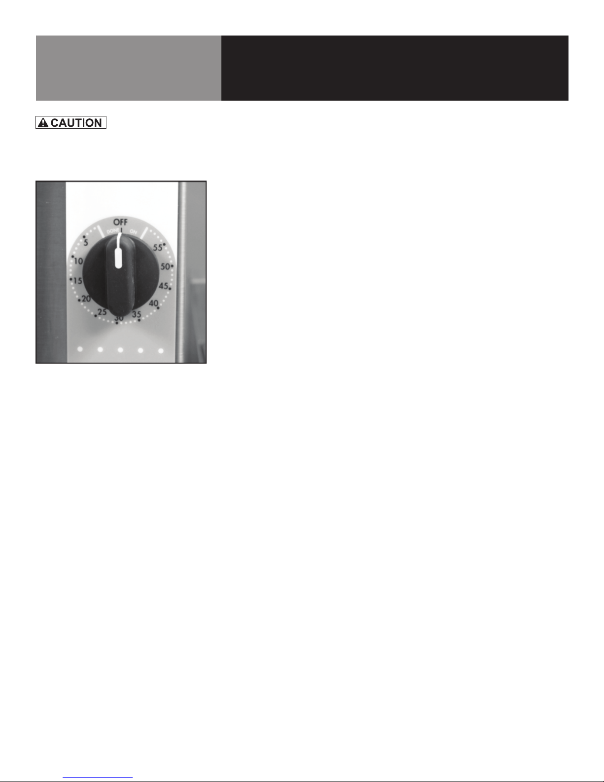
2. 60 minute Timer Control with continuous ON position – See Timer Functions
below.
3. STEAM LEVEL 3-way Toggle Switch – Providing the following options:
• HI PERFORMANCE – For maximum power and fastest cook times (a la
carte cooking);
• ENERGY SAVER – For batch production, with slower cook times but
energy savings; or
• STANDBY – for Ready Mode, with even more energy savings.
4. POWER - ON/OFF Switch
5. Water Reservoir DRAIN VALVE Handle –
• OPEN when at 9:00 o’clock position – Allows water to drain from reser-
voir.
• CLOSED when at 6:00 o’clock position – Allows water to fill reservoir
when Power switch is ON and Timer is set or in (manual) ON position.
The Timer can be used in three ways:
1. In the OFF position, the steamer stays ready for start-up.
2. When a cook time is set, the unit steams until the timer runs down to DONE. At
that time, steaming stops and a beeper sounds until the user turns the knob to
another position.
3. With the timer turned to the ON position, the unit steams continuously.
OPERATING PROCEDURES
1. Make sure Water Reservoir Drain Handle is in “CLOSE” position.
2. Press the ON/OFF switch located on the control panel to ON. The steam generating reservoir will fill.
3. Rotate timer knob to the ON position.
4. Choose STEAM LEVEL: HIGH PERFORMANCE or ENERGY SAVER. In approximately 10-15 minutes the READY light will come on.
5. Load food into pans in uniform layers. Pans should be filled to about the same
levels and should be level on top. This will ensure pan-to-pan cooking consistency.
6. Open the door and slide the pans onto the supports. TIP: If you will only be
steaming one pan, put it in the middle position.
OM-ST-4E/6E 11
Page 12
Operation – General Steamer Use
WHEN YOU OPEN THE DOOR, STAY AWAY
FROM STEAM COMING OUT OF THE UNIT.
STEAM CAN CAUSE BURNS.
7. Close the door. With the READY indicator lit, you can initiate:
TIMED STEAMING: If you want to steam the food for a certain length of time,
set the timer for that period. The timer will automatically run the steamer for
the set time and a beeper will sound when the cook time is complete. Steam
production stops when the timer is turned to OFF.
CONTINUOUS STEAMING: If you want to steam continuously, turn the timer to
the ON position. The unit will continue steaming until you stop it by turning the
timer to OFF. IMPORTANT: When steaming continuously, YOU MUST CONTROL
STEAMING TIME.
8. At the end of the cook time, open the door. Remove the pans from the steamer,
using hot pads or oven mitts to protect your hands from the hot pans.
NOTE: You can open the door at any time to check progress, stir or season
food. When the compartment door is opened, a switch will cut power to the
heating elements, but steam will still roll out of the compartment. IMPORTANT:
Open the door a crack and allow steam to vent before fully opening the compartment door.
9. To shut down the unit, press the POWER ON/OFF switch to OFF.
NOTE: The steamer was designed to drain only when the manual drain is
opened.
10. At end of day or if the steamer will not be needed, open the steamer drain
valve handle to the 9:00 o’clock position, to drain the water from the steam
generator. (See Page 13 for CLEANING INSTRUCTIONS)
12 OM-ST-4E/6E
Page 13
Cleaning
DISCONNECT THE POWER SUPPLY BEFORE
CLEANING THE OUTSIDE OF THE STEAMER.
KEEP WATER AND CLEANING SOLUTIONS
OUT OF CONTROLS AND ELECTRICAL
COMPONENTS. NEVER HOSE OR STEAM
CLEAN ANY PART OF THE UNIT.
AVOID CONTACT WITH ANY CLEANERS,
DELIMING AGENT OR DEGREASER AS
RECOMMENDED BY THE SUPPLIER. MANY
ARE HARMFUL. READ THE WARNINGS AND
FOLLOW THE DIRECTIONS!
EVEN WHEN THE UNIT HAS BEEN SHUT
OFF, DON’T PUT HANDS OR TOOLS INTO THE
COOKING CHAMBER UNTIL IT HAS COOLED.
IMPORTANT
DON’T USE ANY CLEANING AGENT THAT
CONTAINS ANY SULFURIC AGENT OR ANY
CHLORIDE, INCLUDING HYDROCHLORIC ACID
(HCL). TO CHECK FOR CHLORIDE CONTENT
SEE ANY MATERIAL SAFETY DATA SHEETS
PROVIDED BY THE CLEANING AGENT
MANUFACTURER.
To keep your steamer in proper working condition, use the following procedures to
clean the unit. This regular cleaning will reduce the effort required to clean the steam
generator and cavity.
SUGGESTED CLEANING SUPPLIES
1. Mild detergent
2. Stainless steel exterior cleaner Spray DeGreaser
3. Cloth or sponge
4. Brush with soft bristles
5. Spray bottle
6. Measuring cup
7. Nylon pad
8. Towels
9. Plastic disposable gloves
10. Funnel
CLEANING PROCEDURES
1. Exterior Cleaning
a. Prepare a warm solution of mild detergent as instructed by the supplier.
Wet a cloth with this solution and wring it out. Use the moist cloth to
clean the outside of the unit. Do not allow freely running liquid to touch
the controls, the control panel, any electrical part, or any louver on the
rear panels.
b. To remove material which may be stuck to the unit, use a fiber brush or a
plastic or rubber scraper with a detergent solution.
c. Stainless steel surfaces may be polished with a recognized stainless
steel cleaner.
2. Cooking Compartment Cleaning
Daily cleaning must be done in order to reduce the risk of bodily harm, enhance
performance, and prolong the life of your steamer.
IMPORTANT
DO NOT USE ANY METAL MATERIAL
(SUCH AS METAL SPONGES) OR METAL
IMPLEMENTS (SUCH AS A SPOON, SCRAPER
OR WIRE BRUSH) THAT MIGHT SCRATCH ANY
STAINLESS STEEL SURFACE. SCRATCHES
CAN MAKE THE SURFACE HARDER TO CLEAN
AND PROVIDES PLACES FOR BACTERIA TO
GROW. DO NOT USE STEEL WOOL, WHICH
MAY LEAVE PARTICLES EMBEDDED IN THE
SURFACE, WHICH COULD EVENTUALLY CAUSE
CORROSION AND PITTING.
FAILURE TO CLEAN THE STEAMER AS SPECIFIED
COULD RESULT IN BODILY HARM (FROM
SCALDING WATER OVERFLOW) AND DEGRADE
THE PERFORMANCE OF THE STEAMER.
a. Press POWER switch to turn steamer OFF and open steamer door.
IMPORTANT: Allow the steamer to cool completely before cleaning.
b. Remove optional water grate, if used. It can be washed in a dish machine.
c. Remove left and right pan supports by lifting rack up and pulling away
from cavity wall. They can be washed in a dish machine.
d. Use a mild detergent to wipe down the entire steamer cavity to remove
food and water scale particles. Carefully clean float probes if food residue or loose scale is present. NOTE: A thin layer of tightly bound scale
is normal and will not affect steamer performance. If scale is excessive,
then refer to deliming instructions that follow.
e. Clean right front drain opening, right front drain cover, and right rear
overflow drain opening thoroughly to remove any build-up of debris and
make sure the drain is free flowing without blockage. Ensure probes are
free moving and that build-ups have not limited movement.
f. Replace pan supports and water grate, if used. Steamer is now cleaned
and ready to use.
OM-ST-4E/6E 13
Page 14
Cleaning
(SWINGS DOWN)
ALLOW THE STEAMER TO COOL
COMPLETELY BEFORE CLEANING. HOT
SURFACES CAN CAUSE SEVERE BURNS.
IMPORTANT
FAILURE TO CLEAN THE STEAMER AS
SPECIFIED COULD DEGRADE
THE PERFORMANCE OF THE STEAMER.
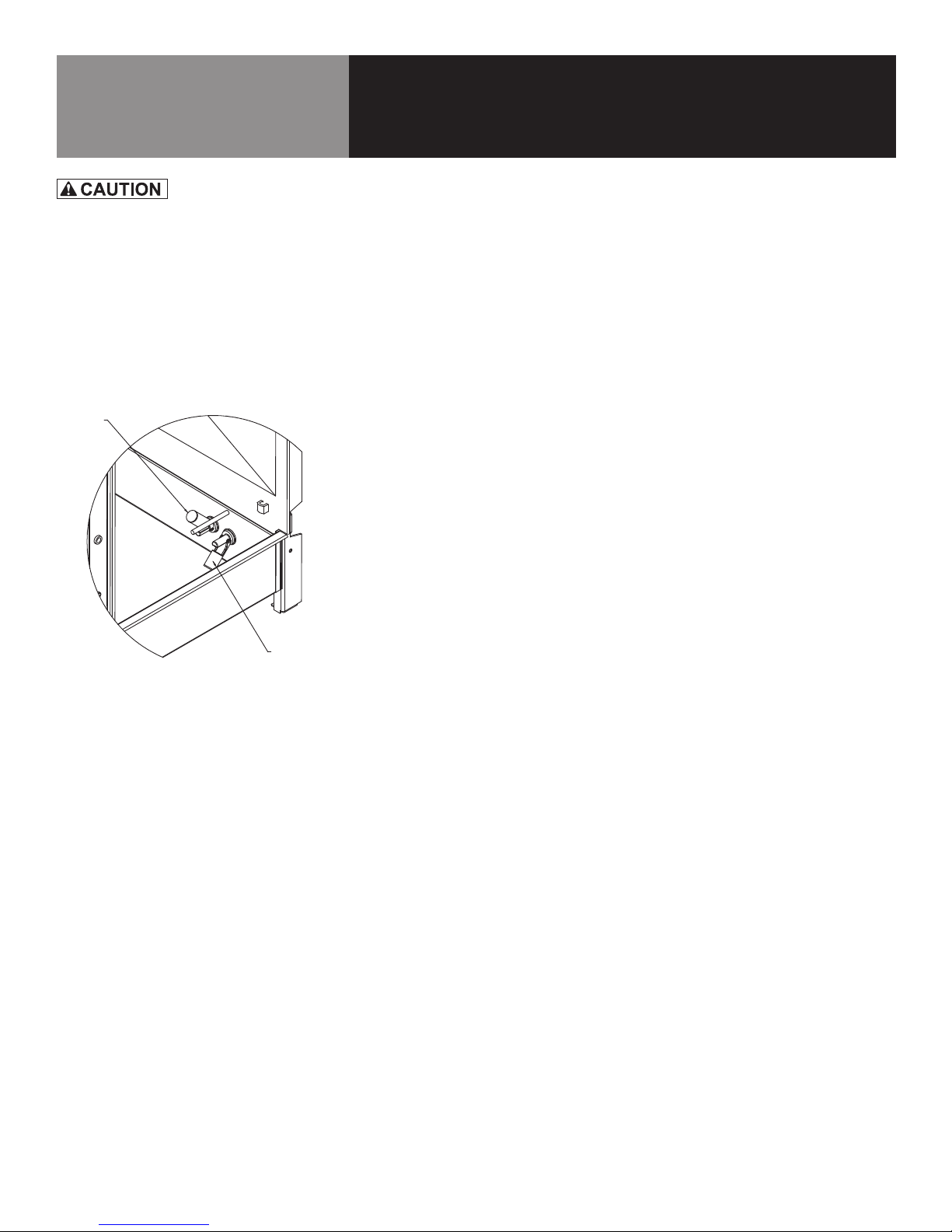
HIGH WATER FL OAT
(SWINGS UP)
3. Cooking Compartment Deliming
When using a Water Treatment System use vinegar as a deliming agent. LoLo
Commercial Foodservice Equipment approved delimer may be used to remove
excessive scale build-up.
a. Follow all cleaning steps A through E on page 13, turn steamer on and
allow water to enter steamer compartment.
b. Pour 1 cup of white vinegar or delimer into steamer compartment and
shut door.
c. Set timer to 30 minutes and allow steam cleaning to occur.
d. After the 30 minute cleaning cycle is complete, turn OFF steamer and
allow it to cool completely.
e. Open steamer door and wipe down the entire steamer cavity to remove
loose scale particles. Carefully clean float probes if loose scale is present.
(See Diagram 14-1 at left)
f. Replace pan supports and water grate. Steamer is now descaled and
ready to use.
LOW WATER FLOAT
Diagram 14-1
NOTE: Inside view of steamer cavity with no
water present. High level float probe swings up.
14 OM-ST-4E/6E
Page 15
Maintenance
USE OF ANY REPLACEMENT PARTS OTHER
THAN THOSE SUPPLIED BY LOLO COMMERCIAL
FOODSERVICE EQUIPMENT OR THEIR
AUTHORIZED DISTRIBUTORS CAN CAUSE INJURY
TO THE OPERATOR AND DAMAGE TO THE
EQUIPMENT AND WILL VOID ALL WARRANTIES.
IMPORTANT
SERVICE PERFORMED BY OTHER THAN FACTORYAUTHORIZED PERSONNEL WILL VOID ALL
WARRANTIES.
The LoLo steamer is designed for minimum maintenance and no user adjustments
should be necessary. Certain parts may need replacement after prolonged use. If
there is a need for service, only LoLo Authorized Service Agents should perform the
work.
STEAM LEAK-DOOR ADJUSTMENT
If steam or condensate is seen leaking from around the door, take the following steps:
1. Check the door gasket. Replace it if it is cracked or split.
2. Inspect the cooking chamber drain to be sure it is not blocked.
3. Check drain line to ensure it is free-venting, not clogged, kinked or restricted in
any way.
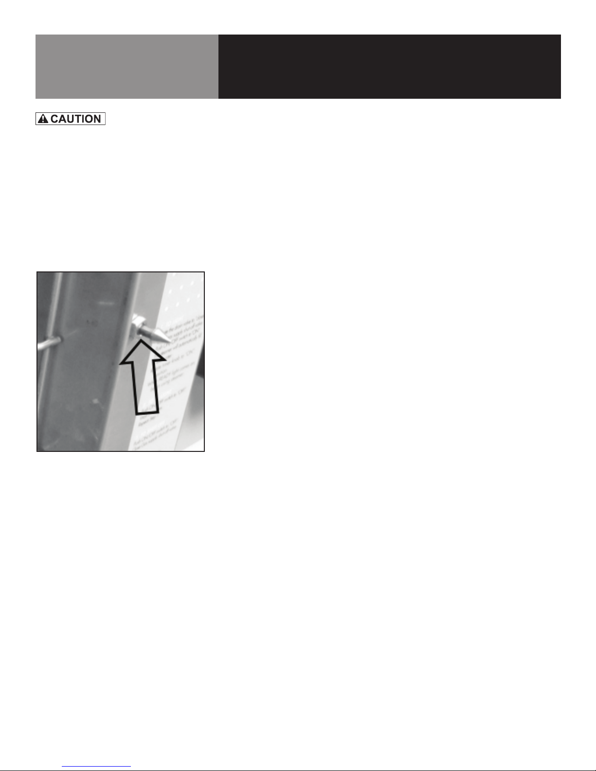
4. Adjust the door latch pin to allow for changes that might occur as the
gasket ages.
• Loosen the lock nut at the base of the latch pin, then turn the latch pin
1/4 turn clockwise, and tighten the lock nut.
• After adjustment, run the unit to test for steam leakage.
• If there is still leakage, repeat the adjustment.
• Continue adjusting the pin clockwise until the door fits tightly enough to
prevent leakage. NOTE: The door hinge may also be adjusted.
Photo 15-1
Latch pin is threaded to change
depth. Lock nut secures it at that depth.
OM-ST-4E/6E 15
Page 16
User Troubleshooting Guide
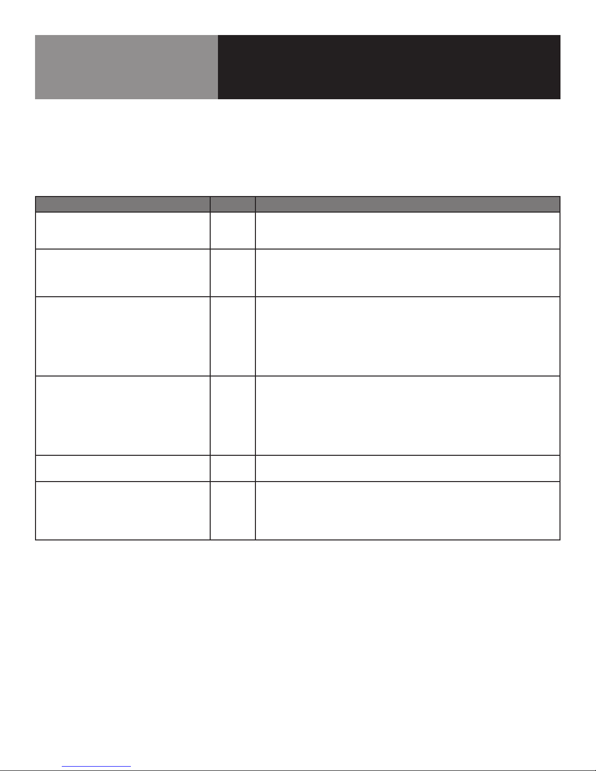
Your LoLo steamer is designed to operate smoothly and efficiently if properly maintained. However, the following is a list of checks
to make in the event of a problem. Wiring diagrams are furnished inside the right side service access panel. If an item on the
check list is marked with and (X), it means that the work should be done by an a LoLo Authorized Service Agent. CAUTION: USE
OF ANY REPLACEMENT PARTS OTHER THAN THOSE SUPPLIED BY LOLO COMMERCIAL FOODSERVICE EQUIPMENT OR THEIR
AUTHORIZED DISTRIBUTORS CAN CAUSE INJURY TO THE OPERATOR AND DAMAGE TO THE EQUIPMENT AND WILL VOID ALL
WARRANTIES.
SYMPTOM WHO WHAT TO CHECK or DO
No power. User a. Check wall outlet circuit breaker.
b. Disconnect power, then check fuses inside steamer. X
c. Call service technician.
Unit overlls with water at start-up. User a. Clean probes in unit.
b. Check oat probe orientation.
c. Clean drain strainer.
d. Call service technician.
Steamer does not ll with water. User a. Is the ON switch depressed?
b. Is the water supply connected?
c. Is the water turned on?
d. Is the water supply hose kinked or obstructed?
e. Check for low water pressure (less than 30 PSI) or low water
ow (less than 2 gpm). X
f. Is the screen at the water connection clogged?
No steam. User a. Is the ON switch depressed?
b. Is the STEAM LEVEL switch in HIGH PERFORMANCE or ENERGY
SAVER?
c. Is the water supply connected?
d. Is the water turned on?
e. Is steamer door completely closed?
f. Is timer set to either ON position or TIMING position?
Any unusual operation. User a. Press ON/OFF switch to turn steamer o. Momentarily turn
circuit breaker o and then turn unit back on.
Door pops open. User a. Ensure drain and vent are not plugged. No more than two
units should be attached to a single drain line.
b. Check door pin adjustment. The door pin is threaded and can be backed
out to catch latch. (See Maintenance Section on page 15)
c. Call service technician.
16 OM-ST-4E/6E
Page 17
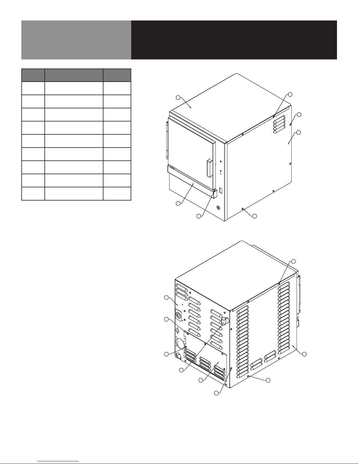
Parts List & Diagram
5
5
7
9
5
5 1
5
10
4-Pan Cabinet Assembly
Item
no.
1
2
3
Description
PANEL, LEFT SIDE
WELDMENT
PANEL, RIGHT SIDE
WELDMENT
WELDMENT, TOP
COVER
Part
number
156503
156502
156396
4 TRAY DRIP 094151
SCREW, TRS HEAD
5
10-32 x 3/8 (QTY 17)
SHOULDER SCREW -
6
DRIP TRAY (QTY 2)
WELDMENT, CAVITY
7
VENT
004173
070467
145297
9 ACCESS PANEL 156488
10
REAR COVER ASSY
ELECTRIC
156332
3
4
6
5
5
5
2
5
10
5
5 1
7
9
5
5
OM-ST-4E/6E 17
Page 18
7
7
7
7
5
7
7
7
7
9
7
2
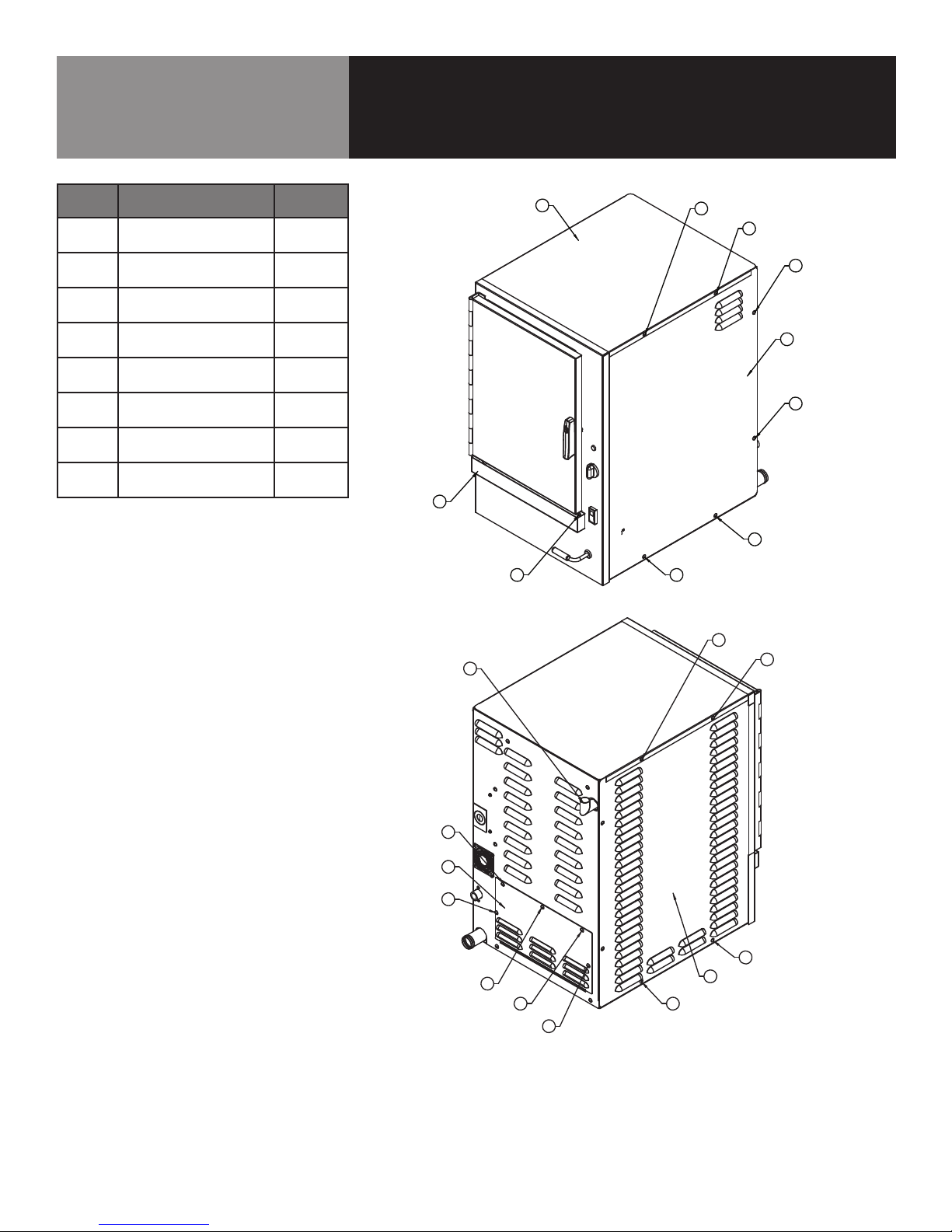
Parts List & Diagram
6-Pan Cabinet Assembly
Item
no.
1
2
Description
PANEL, SIDE RIGHT
ASSY
PANEL, SIDE LEFT
ASSY
number
156151
156152
3 TRAY DRIP 094151
WELDMENT, TOP
4
COVER
WELDMENT, CAVITY
5
VENT NO VACUUM
SHOULDER SCREW -
6
DRIP TRAY (QTY 2)
SCREW, TRS HEAD
7
10-32 x 3/8 (QTY 17)
156396
145297
070467
004173
9 ACCESS PANEL 156507
Part
4
3
6
5
7
7
7
1
7
7
7
7
7
18 OM-ST-4E/6E
7
9
7
7
2
7
7
7
7
Page 19
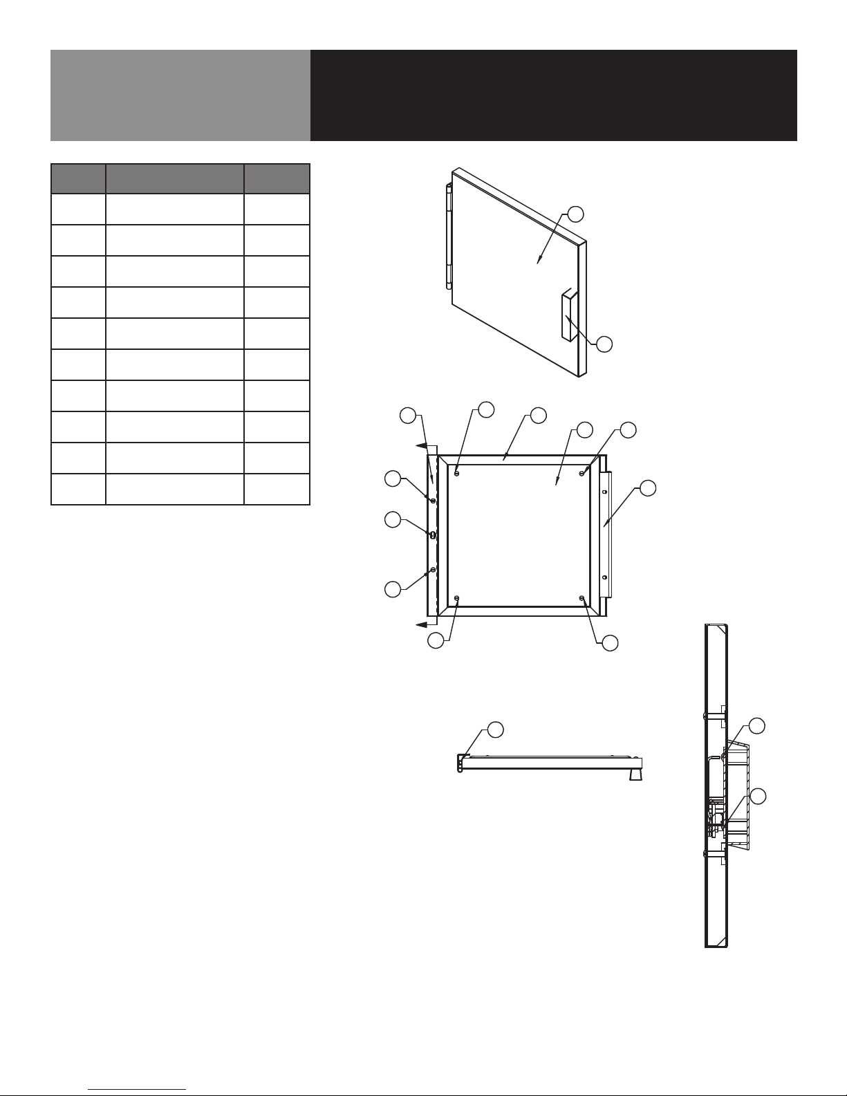
6
Parts List & Diagram
6
7
1
5
5
8
2 3
4
5
5
5
5
9
A
A
ITEM NO. PART NUMBER DESCRIPTION
Default/
QTY.
1 156392 PANEL FRONT DOOR ASSY, 4-PAN 1
4-Pan Door Assembly
Item
no.
1
Description
PANEL FRONT DOOR
ASSEMBLY
Part
number
156392
2 LATCH ASSEMBLY 156390
GASKET, DOOR
3
SILICONE
156388
4 PANEL, DOOR INSIDE 156387
SCREW TRUSS HEAD
5
MACHINE (QTY 6)
SCREW, HEX HEAD
6
CAP, 1/4” - 20 (QTY 2)
005764
005608
7 HANDLE ASSY DOOR 070123
8 HINGE, DOOR 130868
CAM DOOR UNLATCH
10
9
LIFT
SCREW 8-32 x .375
LG PHILLIPS (QTY 2)
074252
129732
2 3
5
A
5
9
1
7
4
5
8
5
A
5
6
5
10
10
SECTION A-A
SCALE 1 : 2
OM-ST-4E/6E 19
Page 20
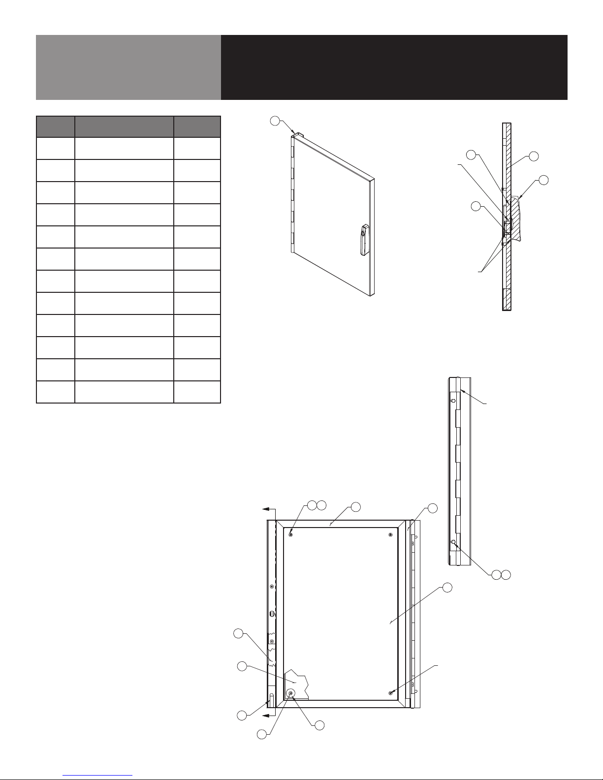
7
15
10
9
11
12
14
3
1
4
2
TORQUE 18-20 IN. Lbs
TYP. ALL SCREWS
ITEM NO . QTY. PART NO. DESCRIPTION
B
B
SECTION B-B
SEE NOTE 1
8
6
9
ITEM (13) APPLIED ON CA M AS
SHOWN AND BETWEEN CAM A ND
INNER SIDE OF FRONT DOOR
4
HINGE AND PIN TO BE COATED W ITH
ITEM 13 (NEVER SEEZ GREASE)
5 15
Parts List & Diagram
SECTION B-B
SEE NOTE 1
8
6
9
ITEM (13) APPLIED ON CA M AS
SHOWN AND BETWEEN CAM A ND
INNER SIDE OF FRONT DOOR
4
SEE NOTE 1
8
6
9
ITEM (13) APPLIED ON CA M AS
SHOWN AND BETWEEN CAM A ND
INNER SIDE OF FRONT DOOR
4
HINGE AND PIN TO BE COATED W ITH
ITEM 13 (NEVER SEEZ GREASE)
5
15
6-Pan Door Assembly
Item
no.
1
Description
PANEL, FRONT DOOR
ASSEMBLY
Part
number
140750
2 GASKET 140748
3 PANEL, DOOR INSIDE 140751
SCREW, 8-32 X 3/8”
4
PHIL HEAD (QTY 8)
SCREW, HEX HEAD
5
CAP, 1/4”-20 (QTY 2)
127179
005608
6 HANDLE 129723
7 HINGE, DOOR 140755
CAM, DOOR
8
UNLATCH LIFT
074252
9 LATCH ASSEMBLY 140752
10
SPACER FOR DOOR
(QTY 4)
071206
11 INSULATOR BOARD 140754
12
BLOCK AND MAGNET
ASSEMBLY
069762
7
20 OM-ST-4E/6E
Page 21
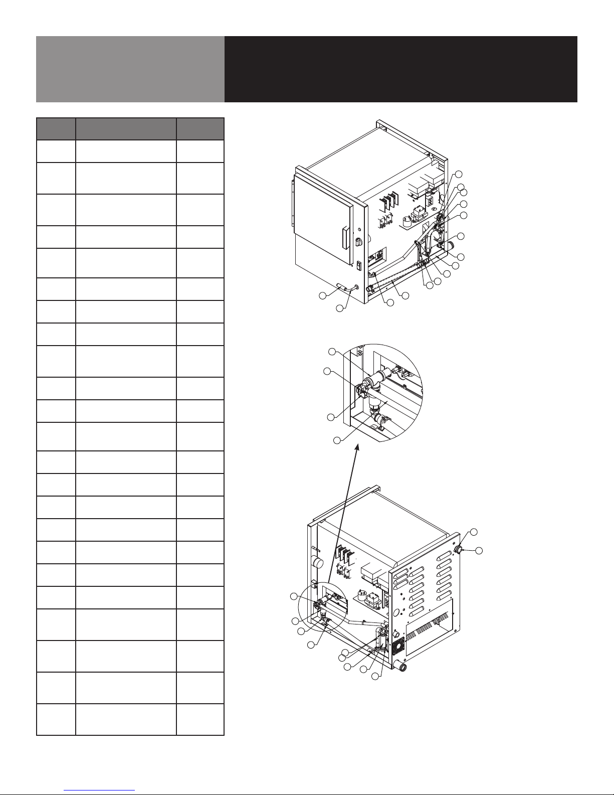
13
2
3
4
5
5
5
5
9
12
11
A
14
17
10
SCALE 1 : 2
DETAIL A
19
Parts List & Diagram
13
2
3
4
5
5
5
5
9
12
11
A
Common Water System Components
Item
no.
1
Description
WELDMENT, DRAIN
MANIFOLD ASSY
number
156483
2 HOSE, SHORT VENT 147566
CLAMP, HOSE,
3
CONSTANT TENSION
127525
(QTY 2)
HOSE, SHORT STEAM
4
INLET
140164
CLAMP, HOSE,
5
CONSTANT TENSION
138457
CTB-27 (QTY 4)
VALVE-WATER FEED
6
3/4R
NUT HEXHEAD KEPS
7
10-32
CLAMP HOSE, LOW
8
PRESSURE (QTY 6)
071235
071256
093482
HOSE, BLACK
9
RUBBER 3/8” ID X
505090
10” LG
10
11
TEE, 1/2” NPT BRASS
ELBOW, 90 DEG 1/2
MPT X 3/8
013650
139126
ELBOW 1/2” NPT TO
12
3/4 HOSE BARB 90
142548
DEG
13
14
MPT TO FPT BRASS
BALL VALVE 1/2” NPT
NUT, HEXAGON 3/824
156478
012809
Part
21
INSIDE HOS E
8
8
6
8
22
23
1
20
INSIDE HOS E
8
7
15
16
10
14
17
19
DETAIL A
SCALE 1 : 2
18
8
15 HANDLE, SHAFT 141668
16
17
18
SHAFT, DRAIN
ACTUATOR
BRACKET, DRAIN
VALVE CONNECTION
HOSE, STEAM UNIT
18” LONG
156479
GVR-0002
125954
19 CLEAR 3/8” HOSE 092124
20
REDUCER, WATER
FLOW, .110 ID
144481
21 REDUCER, FLOW 147371
22 DRAIN THERMOSTAT 156487
23
NUT HEXAGON KEPS
4-40 (QTY 2)
071297
3
2
11
A
13
12
5
9
5
5
4
5
OM-ST-4E/6E 21
Page 22
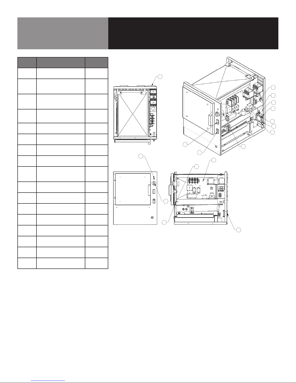
Parts List & Diagram
24.438
ITEM NO.
PART
NUMBER
DESCRIPTION
QTY.
1 162322
CONTROL PANEL ASSEMBLY
ELECTRIC
1
2 069789
SCREW HEX SLOTTED HD W/WASHER
#8-32 X 3/8"
2
3 096826
TIMER STEAMER (ATMOSPHERIC)
1
4 155548
POWER SWITCH, WITH GREEN
INDICATOR LIGHT
1
5 096857
SWITCH, DOOR
1
6 116384
LIGHT, INDICATOR AMBER
1
7 123100
KNOB, TIMER
1
8 096841 SCREW #4-40 X 1/4" HEX MS 2
9 153505
FAN, 24VDC MUFFIN 80MM
1
10 143664
GUARD, 80MM FAN, PLASTIC
1
11 140182
SCREW, 6-32 X 2 LG HEX HD SLOT
4
12 119855
NUT, 6-32 LOCK INSERT
4
13 155508
ST-4E & ST-6E W/ FLOAT 24 VAC
HARNESS
1
14 160874
HARNESS, STEAMER HIGH VOLTAGE
1
15 162338
BASE & CAVITY ASSEMBLY, 4 PAN
ELEC
1
16 162344
SWITCH, THREE WAY
1
17 162429
HARNESS, LOLO E-SAVING MOD
1
Common Electrical System Components
Item
no.
1
Description
CONTROL PANEL
ASSEMBLY ELECTRIC
number
162322
SCREW HEX SLOTTED
2
HD W/WASHER #8-32
069789
X 3/8” (QTY 2)
3 TIMER STEAMER 096826
POWER SWITCH,
4
WITH GREEN
155548
INDICATOR LIGHT
5 SWITCH, DOOR 096857
LIGHT, INDICATOR
6
AMBER
116384
7 KNOB, TIMER 123100
SCREW #4-40 X 1/4”
10
11
12
13
14
15
8
HEX MS (QTY 2)
FAN, 24VDC MUFFIN
9
80MM
GUARD, 80MM FAN,
PLASTIC
SCREW, 6-32 X 2 LG
HEX HD SLOT (QTY 4)
NUT, 6-32 LOCK
INSERT (QTY 4)
FLOAT 24 VAC
HARNESS
HARNESS, STEAMER
HIGH VOLTAGE
BASE & CAVITY
ASSEMBLY, 4 PAN ELE
096841
153505
143664
140182
119855
155508
160874
162338
Part
10
2
11
9
11
12
11
12
16
6
7
5
4
1
8
3
10
16 SWITCH, THREE WAY 162344
17
HARNESS, LOLO
E-SAVING MOD
162429
22 OM-ST-4E/6E
Page 23
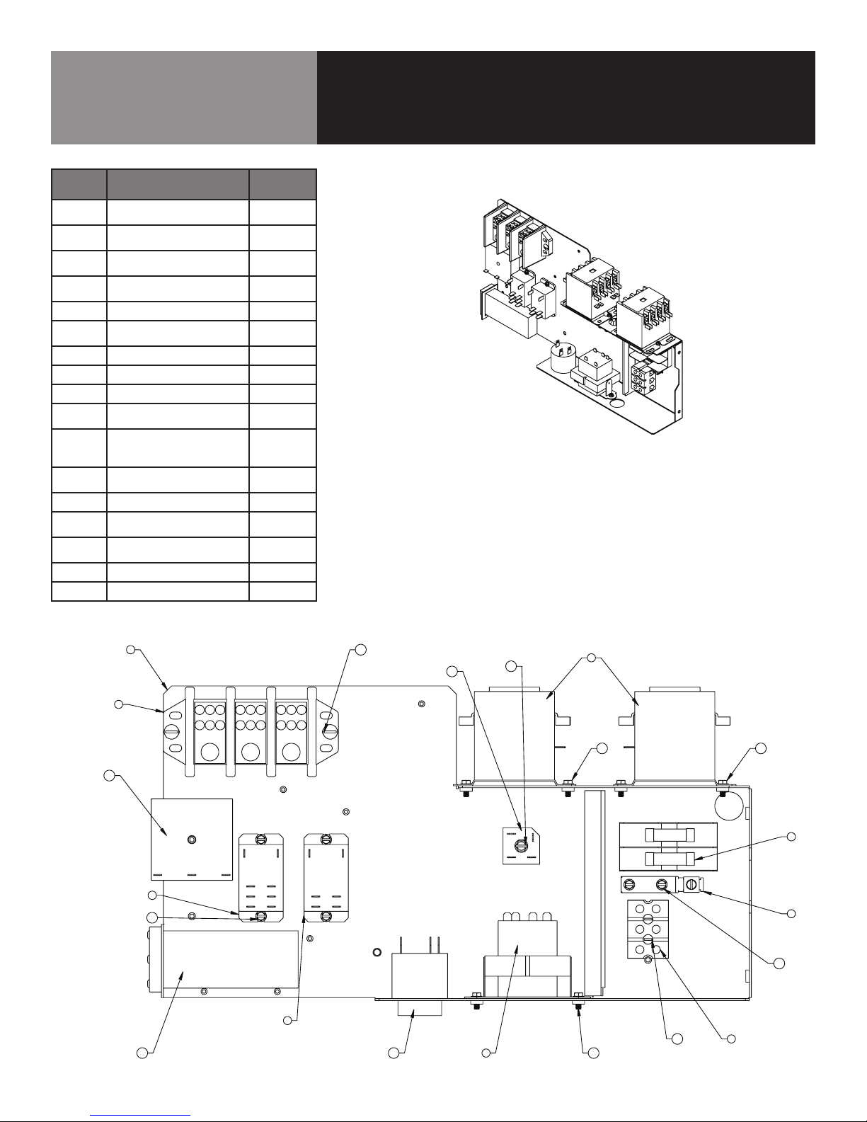
Parts List & Diagram
Electric Control Panel Assembly
Item
no.
1
2
3
4
Description
PANEL, HIGH
VOLTAGE ASSEMBLY
TERMINAL BLOCK
3-POLE
CONTACTOR, 4 POLE
40FLA (QTY 2)
TRANSFORMER,
40VA, 208-240/60/3
Part
number
156402
003888
119811
137441
5 FUSE BLOCK ASSY 160919
MECHANICAL LUG,
6
GROUND, #2-#8
106412
7 TERMINAL BLOCK 070185
8 RELAY, 24 VAC DPST 119814
9 RELAY, 24 VAC DPDT 121733
10
SCREW ROUND HEAD
8-32 1-1/4” (QTY 2)
005056
SCREW HEX SLOTTED
11
HD W/WASHER #8-32
069789
x 3/8” (QTY 12)
12
SCREW, #10-32 x .75
(QTY 2)
116100
13 BEEPER 156486
14
15
SCREW HEX
SLOTTED
RECTIFIER, BRIDGECOMBO
071485
071487
16 TEMP CONTROLLER 26057-2
17 REPEAT CYCLE TIMER 162189
1 12
7
17
9
11
8
16
15
13
14
4 11
3
1111
5
6
11
210
OM-ST-4E/6E 23
Page 24
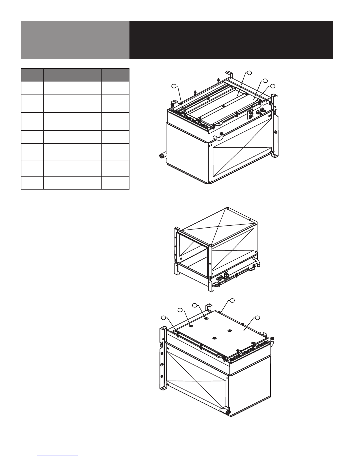
2
3
1
5
UP-SIDE DO WN WITHOUT
INSULATION HO LD DOWN PANEL
Parts List & Diagram
2
3
1
5
UP-SIDE DO WN WITHOUT
INSULATION HO LD DOWN PANEL
2
3
1
5
Electric Heating Elements
Item
no.
Description
number
1 INSULATION (QTY 3) 156320
BRACKET, ELEMENT
2
HOLD-DOWN, LEFT &
069789
RIGHT SIDE (QTY 2)
BRACKET,ELEMENT
3
HOLD-DOWN, MIDDLE
PANEL, INSULATION
4
HOLD-DOWN
144110
096857
ELEMENT, 240V
5a
1.6KW (QTY 9 FOR
096841
6-PAN)
ELEMENT, 240V
5b
1.3KW (QTY 9 FOR
156501
4-PAN)
NUT, HEX KEPS 1/4”-
6
20 (QTY 12)
143559
Part
24 OM-ST-4E/6E
6
6
6
UP-SIDE DO WN WITH
INSULATION HO LD DOWN PANEL
6
4
Page 25
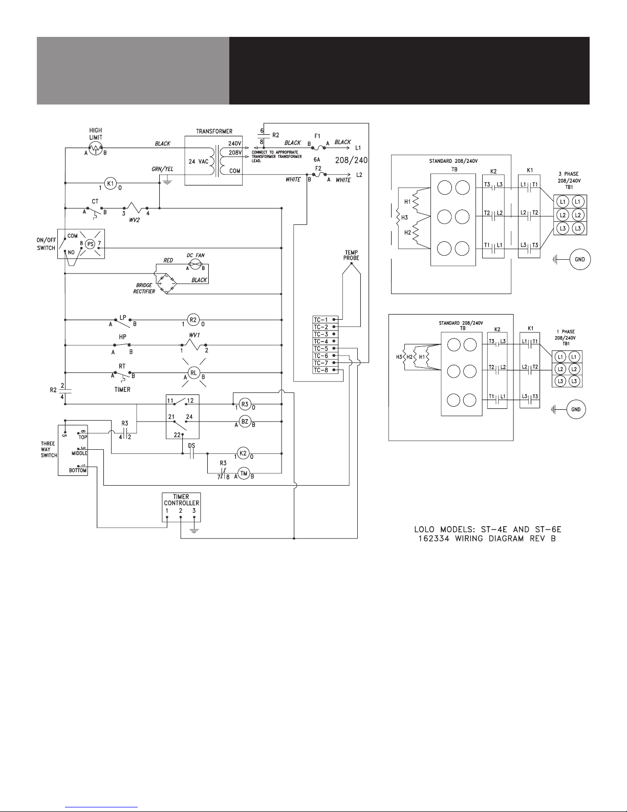
Wiring Diagram
OM-ST-4E/6E 25
Page 26

5925 I-55 South • Byram MS 39272
877-2GO-LOLO (877-246-5656) • Fax 877-504-4073
www.getLoLo.com
© 2014 LoLo Commercial Foodservice Equipment. All Rights Reserved.
PART NUMBER 162326 REV E (12/14)
 Loading...