

Page 1
USB Quick Start Guide
This Quick Start Guide covers preparation,
use and maintenance for the following models:
USRIC-4, USRIC-8 & UTRIX-16
1. SOFTWARE SETUP
Software requirements vary depending on the model of USB Logger you
have and the type of file you want it to generate when plugged into a
USB port.
Loggers can be ordered pre-configured, ready to start. Different
profiles are available; if none of these suit or the Logger needs
different configuration settings to those already installed, you will
need to download and install our freely available companion LogTag®
Analyzer software (version 2.6r4 or higher) from our website: www.
logtagrecorders.com/software. Simply browse to our software page,
fill in your details and begin your download.
“Standard Configuration”
With the Software running, the easiest way to configure your LogTag
for use is with the ‘LogTag Wizard’ which can be accessed by
pressing the ‘F2’ key on your keyboard or you can browse via the top
navigation menu: ‘LogTag’ > ‘Wizard’
Note: You can configure many devices at the same time, however,
it is practical to limit the number of devices to about 10, using a
powered USB hub. It is not possible to configure different models at
the same time.
1
2
3
4
5
6
7
Advanced Configuration Options
®
Click Advanced Options for additional configuration settings.
These settings decide which files -if any- are generated at the end
of the trip and also determine the appearance and contents of the
generated files.
Parameters that influence the appearance of all files are
• Setting of the temperature units used in the files (°F or °C).
• Date and time format
• Time zone and MKT values
Parameters specifically influencing the appearance of the PDF file
are (Not available for USRIC-4):
Once it has finished downloading, install LogTag® Analyzer to your
computer and start the program. (For detailed software download and
install instructions, please refer to the LogTag® Analyzer User Guide).
2. LOGTAG® CONFIGURATION
It is recommended that you connect each USB PDF Temperature
Recorder via a permanently plugged in USB extension cable to protect
your computer’s USB socket. Please refer to www.logtagrecorders.com/
support if you are having issues.
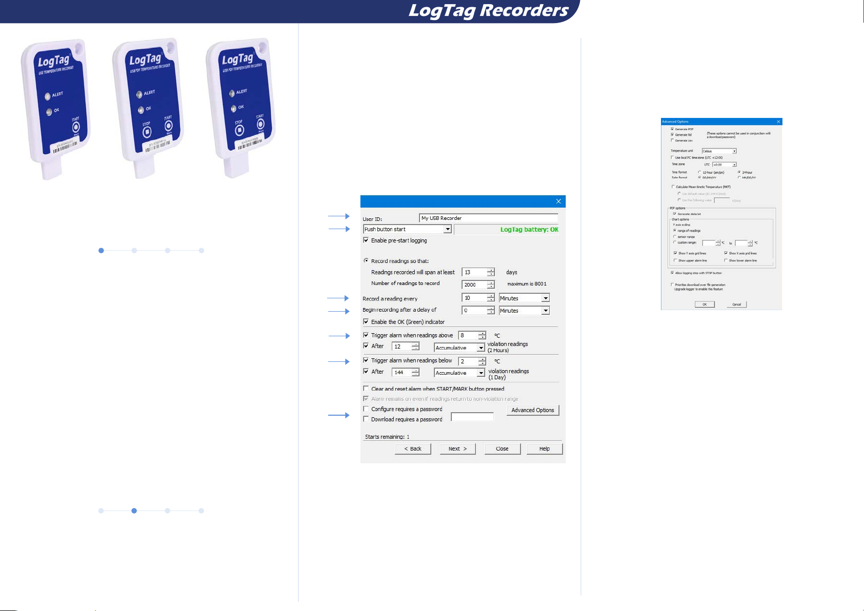
1. Provide a ‘User ID’ to identify the logger being configured.
2. Select Push button or Time/Date start.
3. Enter the recording interval you wish to use. The duration
of the shipment and/or number of readings to record changes
according to the recording interval entered.
4. (Optional) Enter a start delay before the logger begins recording.
5. Specify the upper temperature alarm.
6. Specify the lower temperature alarm.
7. Optionally specify a password for next configure or download.
• Scaling parameters for the chart
• Showing or hiding gridlines
• Showing or hiding alarm threshold lines
• Creation of the data list
Enter the desired options and click Close to accept the new values.
This returns you to the standard configuration dialogue.
Click “Next” to complete the configuration. A progress bar appears
on screen. When this reaches 100%, click “Close” and remove the
logger from the USB port.
Page 2
USB Quickstart Guide
3. START / INSPECT
If “Push Button Start” has been selected:-
Press and hold the START/MARK button until the red and green LED’s start alternate
flashing, then release. Pressing this button will activate the main recording
If “Date/Time Start” has been selected, the logger will automatically start recording at
the appointed time.
• Once the LogTag® has been started, pressing the button will insert an inspection mark
in the data recordings, which is displayed when viewing the data in the software.
• If configured, Alert Conditions can be reset when this button is pressed.
.
4. DOWNLOAD / RESULTS
®
What happens when you plug your LogTag
system of the computer, the settings made during configuration and whether or not
LogTag® Analyzer is running.
into a USB port depends on the operating
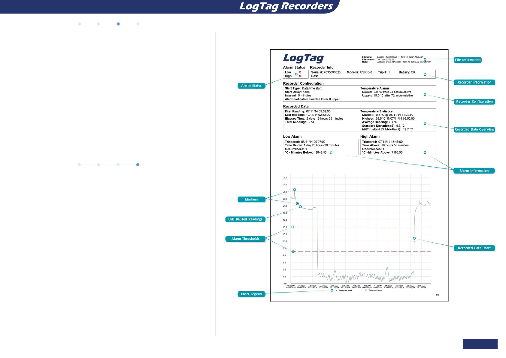
DATA EVALUATION - REPORT
If the LogTag® was configured to generate files, a new drive or mounted device will
appear. The device name will be created from the serial number of the logger. You can
access the files by browsing to the newly created drive and double-clicking the PDF, CSV
or LTD files. For PDF files you need Adobe Acrobat Reader or a similar PDF viewer.
To open the LTD file you need to install the free LogTag® Analyzer software. CSV files can
be opened with a text editor, or imported into a spreadsheet program such as Microsoft
ExcelTM.
You can unplug the logger at any time; there is no need to stop the device.
Page 2 of 3
Page 3
LIGHT PATTERNS
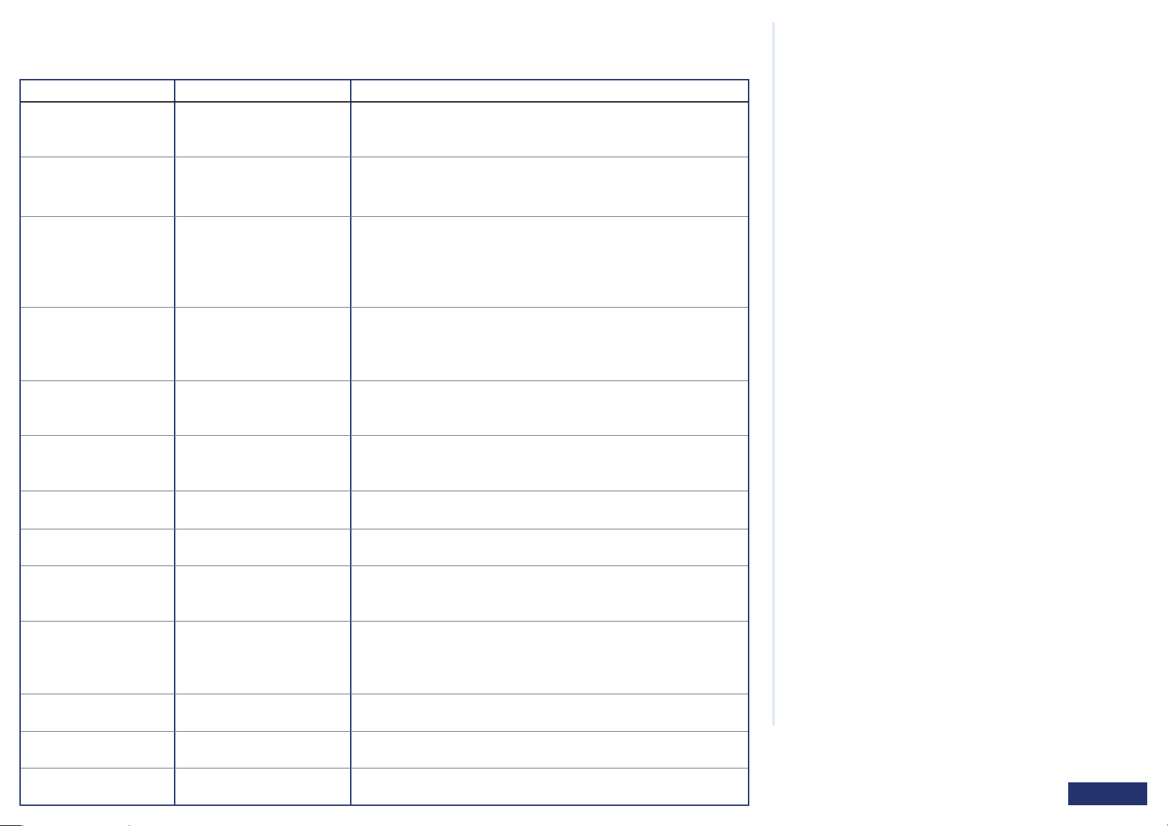
The following table is a useful reference for how your USB LogTag® communicates with the user via the red and green LED’s.
SIGNAL SEQUENCE OCCURRENCE
Wake-up signal
Start signal
Mark signal
Delay signal
Logging active, no alert
present
Logging finished, no alert
present
Logging active, alert
condition present
Logging finished, alert
condition present
Communication
Initiate Stop
Stopping
Ready for USB
Generating Files
Ready for re-flash
Sequence of four quick alternate
flashes of green OK and red
ALERT indicators
Sequence of ten alternate
flashes of green OK and red
ALERT indicators
Sequence of five simultaneous
flashes of green OK and red
ALERT indicators
Single flash of green OK
indicator every 4 seconds
(Approx.)
Single flash of green OK
indicator every 8 seconds
(approx.)
Single flash of red ALERT
indicator every 4 seconds
Single flash of red ALERT
indicator evert 8 seconds
The green OK indicator will flash
occasionally
Sequence of simultaneous
flashes of green OK and red
ALERT indicators for 4 seconds
Sequence of very quick
simultaneous flashes of green
OK and red ALERT indicators for
2 seconds
Two quick flashes of the green
OK indicator every second
The green OK indicator is on
permanently
The red ALERT indicator is on
permanently
• Displayed after configuration has been successfully applied to the logger.
Not to be mixed up with...
• Displayed when the logger starts its recording cycle.
• The delay timer is re-started (followed by Delay Signal).
• Displayed when pressing Start/Mark button while recording to indicate an
inspection mark in the software.
• Displayed directly after the start-up signal following a push button start
where a recording delay has been configured. In this instance the start-up
signal is repeated when the actual recording begins.
• Indicates the logger is recording.
This is not displayed when pre-start is active and the main logging cycle has
not yet started. It is also not displayed when the green LED has been turned
off in the configuration screen.
• Indicates the logger has finished recording.
This is not displayed when the green LED has been turned off in the
configuration screen.
• Indicates the logger is recording, an alert condition has occurred.
• This is not displayed when pre-start recording has been configured and
the recorder has not yet been started.
• Indicates the logger has finished recording and an alert condition was
present during the trip.
• During USB communication the green LED will flash occasionally; no
additional information is conveyed in this.
• This LED sequence appears when the stop sequence is initiated and
requires that the STOP button is enabled.
• When this LED sequence starts, the STOP button must be released for the
recorder to stop.
• The logger is connected to a USB port and waiting for USB
communication.
• The logger is generating files. No USB activity will be observed on the
computer screen during this time.
• The logger is ready to receive new firmware. Special software is required
to upload new firmware to the logger.
BATTERY REPLACEMENT
Some LogTag® products have a replaceable battery, some of which
may be soldered to the electronics to avoid contact issues that exist
with other branded loggers; for these you will need some soldering
expertise and a battery replacement kit from your distributor.
Please also note that the products do contain a non-rechargeable
Lithium Battery, which must be disposed of in accordance with local
regulations.
HIBERNATION
To prolong the life of your logger you can hibernate it between trips
via LogTag® Analyzer when it is not being used for extended periods.
Please refer to the User Guide in the section about Hibernation.
CALIBRATION
All LogTag® products can be calibrated with special utility software,
which will be made available to calibration labs upon request.
Re-calibrated loggers can be identified and traced back to the
calibrating lab thus reducing the risk of fraudulent data tampering.
WATER INGRESS
Please carefully observe the IP rating for your unit and remember that
none of the LogTag® products can be immersed into liquids.
Page 3 of 3
 Loading...