

General Quickstart Guide
This quickstart guide covers preparation,
use and maintenance for the following models:
TRIX-8, TRIX-16, SRIC-4, TREX-8, TRIL-8, SRIL-8 & TREL-8
1. EQUIPMENT SETUP
Before you can use your LogTag® data logger, it needs to be congured
with several parameters. For this, you need a communication interface,
such as the LTI-HID1, and the free companion software LogTag® Analyzer
from our website.
Browse to the software page at https://logtagrecorders.com/software/,
complete the form with your details and begin the download. Once nished,
install LogTag® Analyzer, then start the program. (For detailed software
download and install instructions, please refer to the LogTag® Analyzer User
Guide).
Connect the interface to your computer. A message will conrm when the
interface driver was successfully installed. You can now congure your
logger.
1 You only require 1 Interface Cradle for all non-USB LogTag® products. You can
however, connect as many Cradles as you like if you wish to congure multiple
loggers simultaneously.
2. LOGTAG® CONFIGURATION
Insert the LogTag® into the Interface Cradle, contacts at the bottom and
the LEDs towards the front of the interface. Start the software and use the
LogTag Wizard, which can be accessed by pressing F2 or by clicking
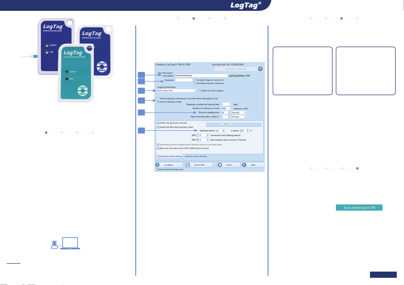
Wizard from the LogTag menu. Following dialogue will be shown:
1
6
2
3
4
5
1. Add a description for the logger or the goods it accompanies
2. Select Date/Time start, or Push button start (with pre-start readings).
3. Specify how long you wish to record for (optional start delay).
4. Choose the time duration between each reading.
5. Specify the upper and lower temperature alarms.
6. Optionally, specify a password for next congure or download.
Complete any other entries as required for your trip, then click Congure.
You can remove the logger from the interface when you see the success
message.
Every LogTag® model is unique in specication. For more information on
conguring the advanced conguration options of your model please refer
to the feature’s description in the LogTag® Analyzer User Guide.
You are now ready to start and deploy the logger. If your model has an
external probe, plug it in before the recording starts.
3. START / INSPECT
Depending on your selection during conguration, the logger may start
recording by itself, or require a manual start.
Date/Time start
If you congured the logger
for a Date/Time start, simply
wait until this time has
passed. The logger will start
recording automatically.
• We recommend enabling pre-start logging, so data is not lost if the user
forgets to press the button. Temperatures will be recorded even before
the trip is started.
• A start delay can be useful, if you need the logger or probe to acclimatize
before the recording of data begins.
• After the LogTag® started logging, pressing the button will insert an
inspection mark in the data recordings, which is displayed when viewing
the data in the software.
• If congured, Alert Conditions can be reset when this button is pressed.
Push-Button Start
To start the logger, press
and hold the Start/Mark
button until the red and
green LEDs start ashing,
then release.
4. DOWNLOAD / RESULTS
At the end of the trip, download your data to your PC for analysis, sharing
and archiving. TRIL-8 and SRIL-8 models require warming to room
temperature before communication should be attempted.
1. Open LogTag® Analyzer. Make sure .
2. With the Interface Cradle connected to the PC, insert the LogTag®.
3. LogTag® Analyzer will automatically download the readings from the
Logger and display a temperature chart.
4. At the same time, a le with the data is saved to the Documents - My
LogTag Data folder on your PC (or the folder you have specied when
setting up the software)
5. If Auto-download is OFF, you can still manually download the readings
by pressing F4 or by clicking Download from the LogTag menu and
following the on-screen instructions.
Page 1 of 2

General Quickstart Guide
LIGHT PATTERNS
The following table is a useful reference for how your LogTag indicates its operational status to you via the red and green LEDs.
SIGNAL SEQUENCE OCCURRENCE
LogTag® wake-up signal
LogTag® start-up signal
Mark signal
Logging active, no alert
present
Logging nished, no alert
present
Alert condition present
Communication
Start button press
4 alternate ashes of green/red
LED’s
16 alternate ashes of green/red
LED’s
5 simultaneous ashes of green/
red LED’s
Single ash of green LED every 4
seconds
Single ash of green LED every 8
seconds
Single ash of red LED every 4
seconds
The green LED will ash
occasionally
Red LED glows faintly This is by design but conveys no information.
PROBES
TREX-8 and TREL-8 models use external probes to measure temperature.
Please ensure you are using the correct probe, as they cannot be swapped
between models. TREX-8 loggers use the ST100 series of probes,
identiable via their blue sleeve. The TREL-8 uses the ST10 series with a
green sleeve. More information about the different probes that are available
for the different LogTag products can be found on our website.
• Displayed after conguration has been successfully applied to the LogTag®.
• When a LogTag® is woken from Hibernation state.
Displayed when the LogTag® starts its recording cycle.
• Displayed when pressing START/MARK button while recording to indicate an
inspection mark in the software.
• Displayed directly after the start-up signal following a push button start where
a recording delay has been congured. In this instance the start-up signal is
repeated when the actual recording begins.
• Indicates the LogTag® is recording.
• This is not displayed when pre-start is active and the main logging cycle has
not yet started. It is also not displayed when the green LED has been turned
off in the conguration screen.
• Indicates LogTag® has nished recording.
• This is not displayed when the green LED has been turned off in the
conguration screen. Will also be displayed when unit has been woken up
from hibernation.
Displayed when the LogTag® has been detected an alert condition and the Alert
LED has been activated.
If an alert is present you cannot determine if the unit is still logging or has nished
its log cycle. If the Alert LED has not been activated during conguration, in
essence the visual indicators have been disabled, and the green LED will ash
every 4 or 8 seconds as above.
During communication with the interface the green LED will ash occasionally; no
information is conveyed in this.
CALIBRATION
All LogTag® products can be calibrated and adjusted, using dedicated utility
software, which is made available to calibration laboratories on request.
Adjusted loggers can be identied and traced back to the calibrating lab for
a traceable history.
REV H 210506 - © Copyright 2021, LogTag North America Inc. All rights reserved.
HIBERNATION
To prolong the life of your logger you can hibernate it between trips via
LogTag® Analyzer, especially when it is not being used for extended periods.
Please refer to the LogTag® Analyzer User Guide, specically the section
about Hibernation.
BATTERIES
When the software indicates that a logger’s battery is low,
the product has reached the end of its life and must be
replaced. The models listed in this guide each contain a
non-replaceable, non-rechargeable Lithium Battery, which
must be disposed of in accordance with local regulations.
Do not expose the logger to extreme temperatures as it may lead to the
destruction of the battery and may cause injuries.
Keep out of the reach of children.
WATER INGRESS
Please carefully observe the IP rating for your unit and remember that none
of the LogTag® products can be immersed into liquids.
CONTACT CLEANING
Keep the three metal contacts at the back of the logger clean and free
from tape residue, dirt or other contaminants, which can all result in
communications problems. If required, clean them with a soft pencil eraser,
but don’t use abrasive materials, as this may cause permanent damage.
ACCESSORIES
Several accessories are available for your product, such as different probes,
glycol and sand buffers as well as waterproof enclosures and wall mount
brackets.
Please enquire with your sales partner for more details.
SUPPORT
If at any stage you feel you need further help, please contact your sales
partner or visit LogTag’s support website at http://logtagrecorders.com/
support for assistance.
Page 2 of 2
 Loading...