

Page 1
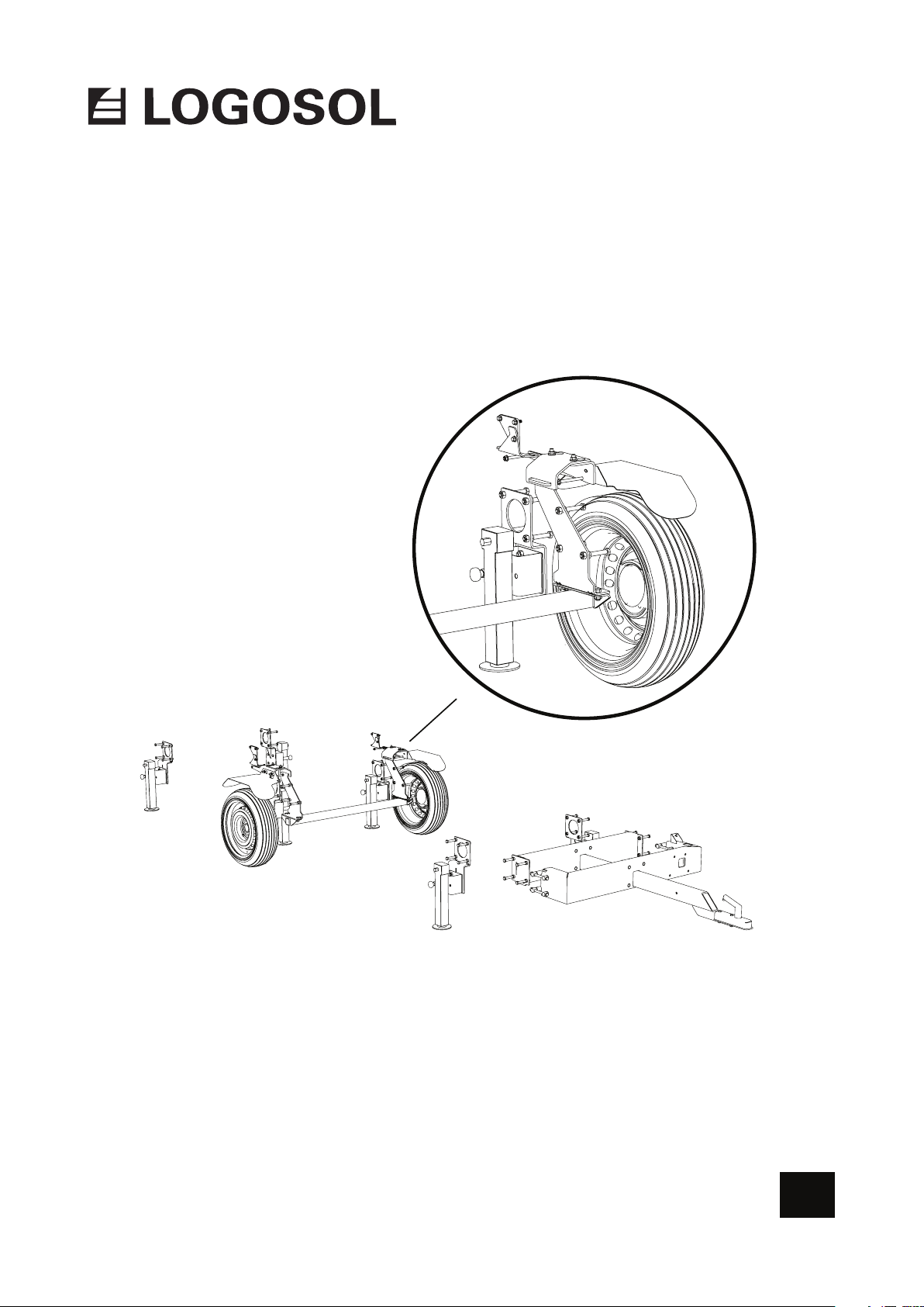
USER MANUAL
Art.nr. 0458-395-0681
TRAILERKIT G2
B10 01
EN
Page 2
THANK YOU FOR CHOOSING A LOGOSOL MACHINE!
We are very pleased that you have demonstrated your condence in us by purchasing this
product, and we will do our utmost to meet your expectations.
Logosol has been manufacturing sawmills since 1989. In that time we have supplied
approximately 50,000 machines to satised customers the world over.
We care about your safety as well as we want you to achieve the best possible results with
your equipment. We therefore recommend that you take the time to carefully read this user
manual from cover to cover in peace and quiet before you begin using the product.
We hope you get a lot of satisfaction from the use of your new equipment.
Bengt-Olov Byström
Founder and chairman,
Logosol in Härnösand, Sweden
Read through the user manual carefully
and make sure you understand its
contents before you use the equipment.
This user manual contains important
safety instructions.
WARNING! Incorrect use can result in
serious or fatal injuries to the operator
or others.
LOGOSOL continuously develops its products.
For this reason, we must reserve the right to modify
the conguration and design of our products.
Ref. No. User Manual, English: 0458-395-0681
Document: User Manual for Trailer Kit
Text: Martin Söderberg
Illustrations: Martin Söderberg
Last revised: January 2019
© 2018 LOGOSOL, Härnösand Sweden
#2
Page 3

TABLE OF CONTENTS
Safety instructions 4
Exploded view 6
Components 7
Assembly 9
Functions 19
Page 4

SAFETY INSTRUCTIONS
• Read carefully through the entire user manual before
starting to use the equipment. Failure to observe
these safety instructions may result in fatal injuries.
• Make sure that everyone who uses the sawmill is
well informed of the dangers and has read the user
manual. The user manual shall always be available
to the persons working with the sawmill. This also
applies where the sawmill is sold or loaned out.
• Minors under 18 years of age are not allowed to
operate the sawmill.
• Make sure that children and animals are not in the
vicinity when the sawmill is being operated.
• Respect the safety distances to avoid injuries from
high noise levels and from a broken blade that is
thrown off.
• Anyone working with the sawmill must be t for
work, healthy and in good physical condition. Make
sure you take regular breaks when operating the
machine. Never operate the machine while under
the inuence of alcohol, narcotics or other drugs or
medicines that can cause drowsiness or inattention.
Key to symbols
For your own safety, read through the entire user
manual carefully and do not start the machine
before you have understood everything.
Use approved ear protectors and protective
eyewear. Hearing can be damaged even after
short periods of exposure.
Sharp rotating tools. Make sure that your ngers
never come near the cutting tools.
This symbol means ’WARNING’. Pay particular
attention where this symbol appears in the
manual text.
This symbol is followed by instructions that must
be observed. Pay particular attention where this
symbol appears in the manual text.
• Only work with the equipment where visibility is
good. Never work with the equipment in the dark or
where visibility is poor.
• Make sure there are other persons within earshot
who you can summon if you need help.
• Only add extra equipment to the sawmill that is
made by Logosol or that is specically approved by
Logosol for the purpose. Other equipment can cause
accidents and should not be used. Logosol will not
accept liability for personal injury or material damage
that occurs while using non-approved attachments
on the sawmill.
• Always wear protective clothing and use personal
protective equipment: Close-tting work overalls
are appropriate. Never operate the sawmill wearing
loose-tting clothes, overall coats or similar.
• Use safety shoes with high-grip soles and steel
toecaps. Neckerchiefs, ties, jewellery or other items
that can get caught in the equipment are not to be
worn.
Page 5
SAFETY INSTRUCTIONS
THE WORKSITE
WARNING! Never operate a band sawmill with
a petrol-powered engine in enclosed or poorly
ventilated areas. This can result in death due to
suffocation or carbon monoxide poisoning.
Only operate the band sawmill and handle band
blades in full daylight or under adequate lighting.
Keep the work area free from clutter, pets, children,
obstacles or other things that can distract the
operator.
Choose a worksite where the ground is hardpacked
and level, with plenty of space for the band sawmill,
a pile of logs and sawn timber. If possible, place
the band sawmill so that the sawdust blows away
from the operator. Set up the band sawmill on level
ground with at least 5 m of free space without any
obstacles around the equipment. If the band sawmill
is to be set up permanently, we recommend that
you support the rail frame with concrete plinths or
wooden blocks (15 cm x 15 cm) under each cross
bunk.
MOVING THE BAND SAWMILL
WARNING! Risk of crush injuries.
Keep people and pets outside the 5 m danger area
around the machine while lifting and moving the
machine parts. Secure the load during transport.
The sawmill trailer may only be moved when the
sawhead is secured laterally and vertically on the
rails as described in this manual.
Securing the sawhead: Secure the sawhead as
described in this manual, using the supplied locking
mechanism, before moving the sawmill.
Always keep an ABC re extinguisher (min. 3 kg)
easily accessible at the worksite.
Always keep a fully-stocked rst-aid kit easily
accessible at the worksite.
Page 6
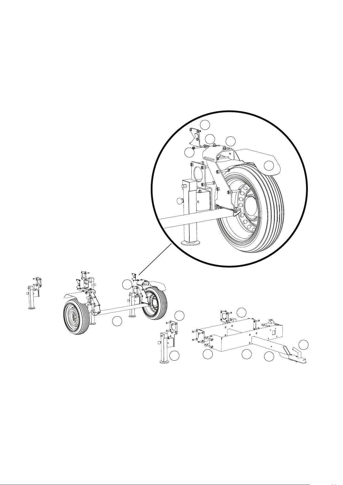
EXPLODED VIEW
Below the components are described to assist in
identifying them during assembly.
13
1 Trailer coupler
2 Drawbar
3 Drawbar beam
4 Cross beam
5 Support leg mount
6 Support leg
7 Wheel axle
8 Rail frame reinforcement
9 Fender
10 Sawhead lock
11 Lock bracket
12 Lower mount
13 Top mount
14 Joint pin
10
12
8
11
9
7
5
6
15
4
1
3
2
Page 7
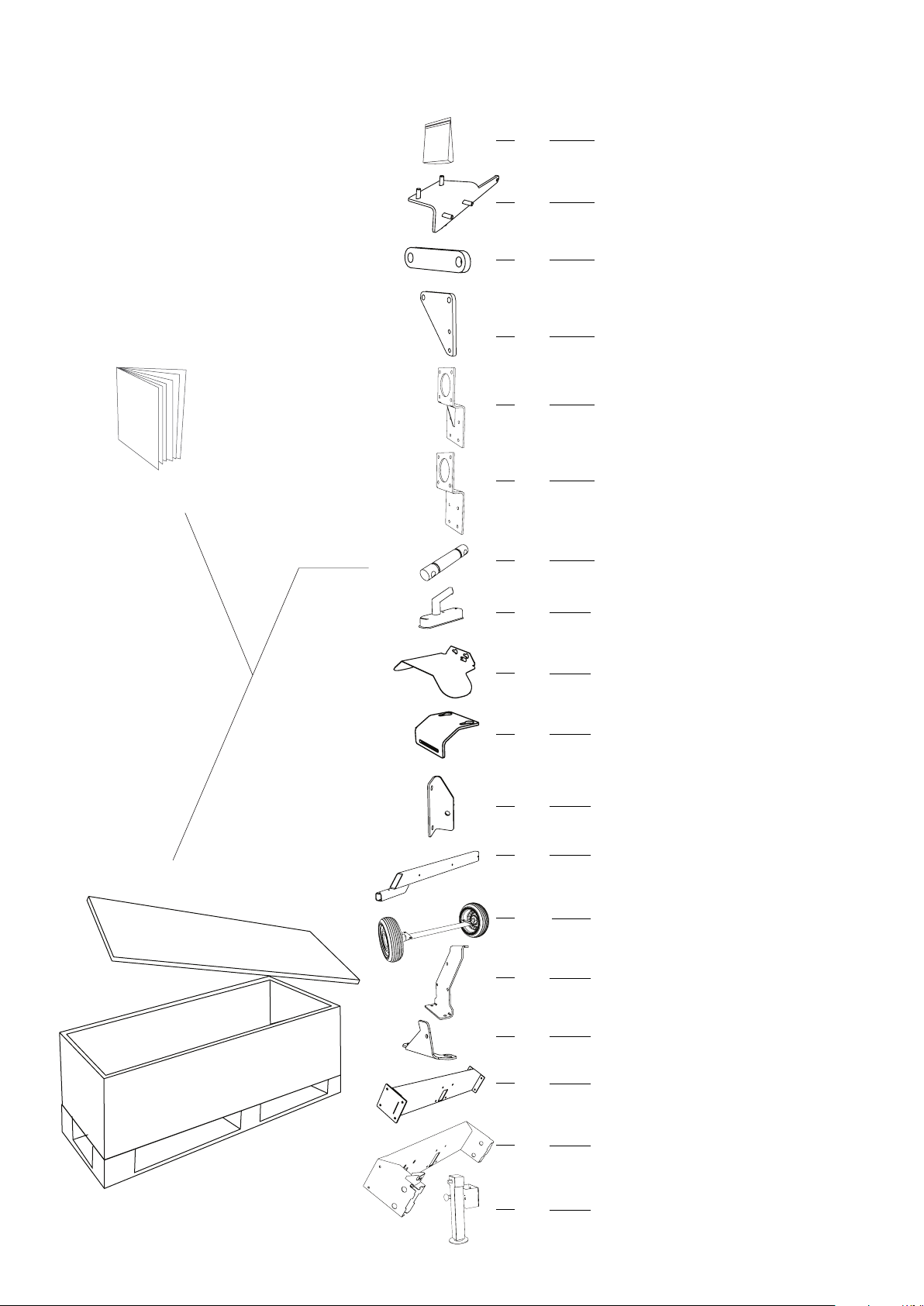
TRAILER KIT
COMPONENTS
Check that all components
are included in the shipment.
User manual
1x
2x
1x
2x
4x
8x
Bolt bag
Sawhead lock
Spacer
Top mount
Support leg mount, L
Support leg mount, R2x
Joint pin
04-00226
L,
02-00380
R,
02-00381
03-02342
03-0243
02-00387
03-02381
00-00000
1x
2x
2x
4x
1x
1x
2x
2x
Trailer coupler
Fender
Lock bracket
Drawbar mount
Drawbar
Wheel axle
Wheel axle mount
Lower mount
04-00238
V,
03-02347
H,
03-02349
03-02312
L,
03-02279
R,
03-02278
02-00368
04-00236
04-00237
L,
03-02384
03-02382
R,
03-02344
1x
1x
6x
Cross beam
Drawbar beam
Support leg
SF-60-280
03-01814
02-00392
04-00269
7
Page 8
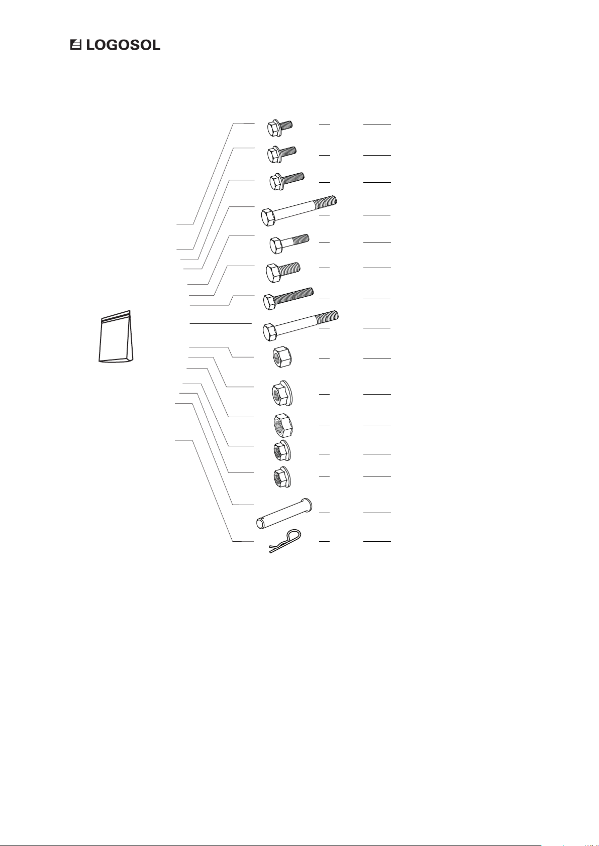
2x
Flange bolt M8x12
Skruvpåse
2x
2x
4x
2x
28x
70x
8x
54x
70x
4x
Flange bolt M8x20
Flange bolt M8x25
Hex bolt M8x100
Hex bolt M10x65
Hex bolt M12x25
Hex bolt M12x90 ISO 4017
Hex bolt M12x140
Hex nut M12 DIN
Flange nut M12
Lock nut M12
10x
4x
2x
2x
Flange lock nut M10
Flange lock nut M8
Cylindrical bolt 12x80
Spring cotter pin
8
Page 9
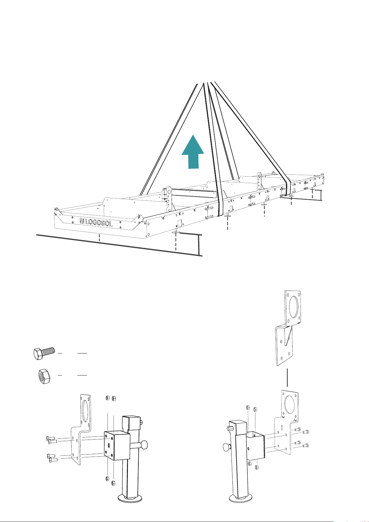
ASSEMBLY
Start assembling by raising the rails in a
safe and efcient way, until the rail tubes
are 400 mm above the ground. This is
the minimum clearance required to t the
support legs.
TRAILER KIT
400mm
400mm
Note that the support legs have two different types of attachment
mounts. There are four reinforced mounts. These should be tted as in the
illustration to the right. The other two mounts should be tted as in the
illustration to the left.
24x
24x
Hex bolt M12x 90
Lock nut M12
9
Page 10
ASSEMBLY
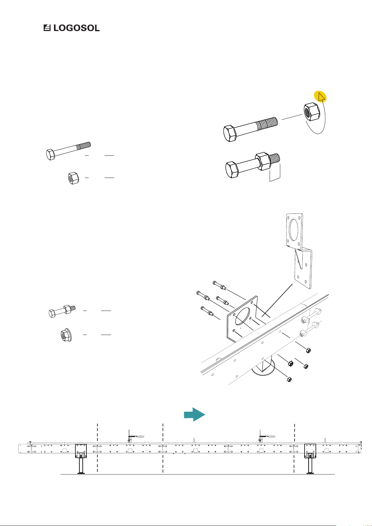
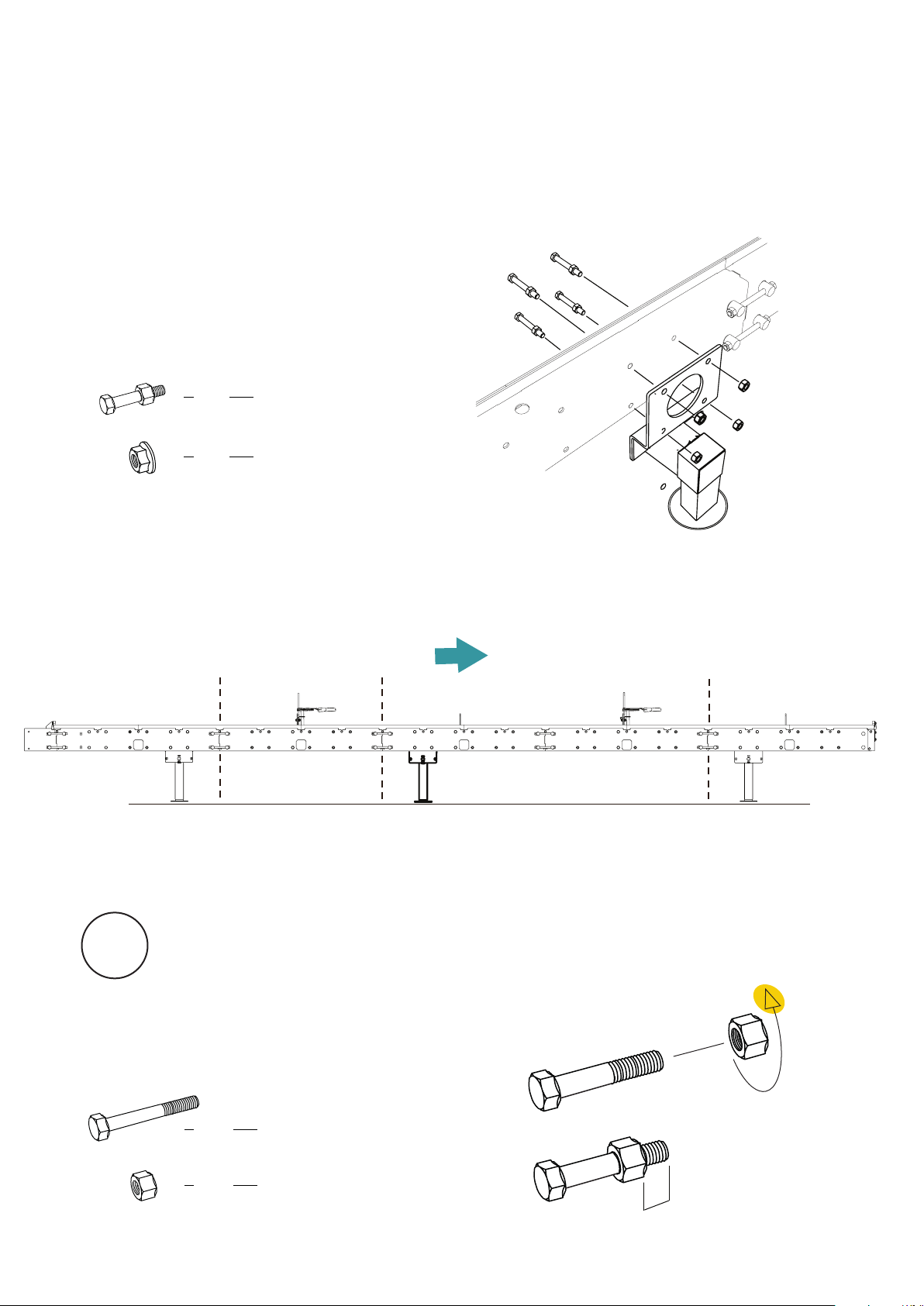
Prepare the bolt joints for the support legs. Screw
the nuts onto the bolts until 20 mm of threading
is visible.
24x
24x
Fit the four support legs that have reinforced
mounts to the rail frame. Note that the attachment
mounts should be tted to the inner side of the rails
with the support legs facing outwards. Check the
recommended position for the support legs in relation
to the rail tube joints in the illustration below.
16x
16x
Hex bolt M12x 90
Hex nut M12
Bolt joint
Flange nut M12
20 mm
10
Sawing direction
Page 11
MONTERING
Fit the other two support legs. Here, the attachment
mounts should be tted to the outside of the rails
with the support legs facing inwards. Check the
recommended position for the support legs in relation
to the rail tube joints in the illustration below.
TRAILER KIT
8x
8x
Bolt joint
Flange nut M12
Sawing direction
1
Prepare the bolt joints for the rest of the assembly.
Screw the nuts onto the bolts until 20 mm of
threading is visible.
22x
22x
Hex bolt M12x 90
Hex nut M12
20 mm
11
Page 12
ASSEMBLY
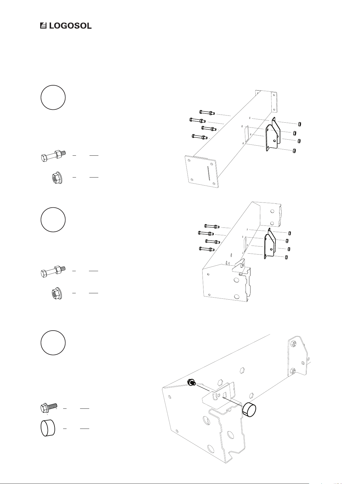
2
Fit the drawbar mounts to the cross beam.
4x
4x
Bolt joint
Flange nut M12
3
Fit the drawbar mounts to the drawbar beam.
4x
4x
Bolt joint
Flange nut M12
12
4
Fit the end cap to the drawbar beam.
1x
1x
Flange bolt M8x12
Rubber end cap
Page 13
ASSEMBLY
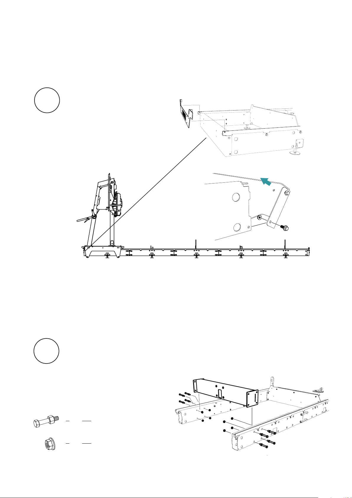
5
Remove the bed end plate and the inner end plate
from the end of the rail frame tubes. Note that the
drawbar beams of the trailer kit should be tted at the
start of the rail frame seen from the sawing direction.
TRAILER KIT
6
Fit the cross beam with bolts in the rst hole pattern
at the rail frame end. Finger-tighten the bolt joints.
8x
8x
Bolt joint
Flange nut M12
13
Page 14
ASSEMBLY
7
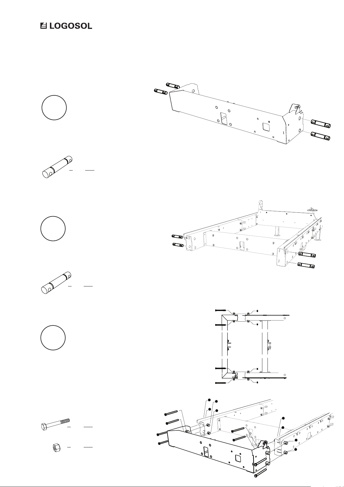
Insert joint pins in the drawbar beam.
4x
Joint pin
8
Insert joint pins in the rail frame end.
4x
Joint pin
14
9
Fit the outer drawbar beam to the rail frame end.
Make sure the joints are level with each other and then
alternately tighten the interior and exterior nuts until
the rail frame tubes match each other. When a good t
is reached, you tighten the bolt joints on both the inner
and the outer drawbar beam.
8x
8x
Hex bolt M12x140
Hex nut M12
Page 15
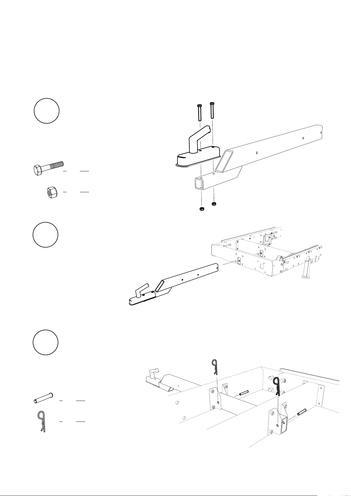
ASSEMBLY
10
Fit the trailer coupler to the drawbar.
TRAILER KIT
2x
2x
Hex bolt M10x65
Hex nut M10
11
Install the drawbar in the drawbar beams.
12
Secure the drawbar with spring cotter
pins in the drawbar beams.
2x
2x
Cylindrical bolt
Spring cotter pin
15
Page 16
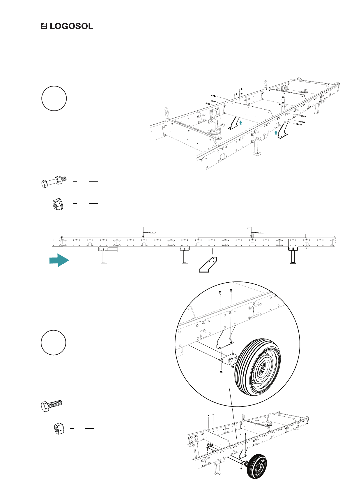
ASSEMBLY
13
Fit the wheel axle mounts to the rail
frame. Note their lateral position on the
rail frame. The wheel axle mounts should
be tted right under the fourth joint (the
drawbar beam joint is included) seen
from the sawing direction.
Sawing direction
14
6x
6x
Bolt joint
Flange nut M12
16
Fit the wheel axle to the wheel axle mounts.
Note the position of the wheelaxle mounts on
the rail frame, shown in the illustration.
4x
4x
Hex bolt M12x25
Lock nut M12
Page 17
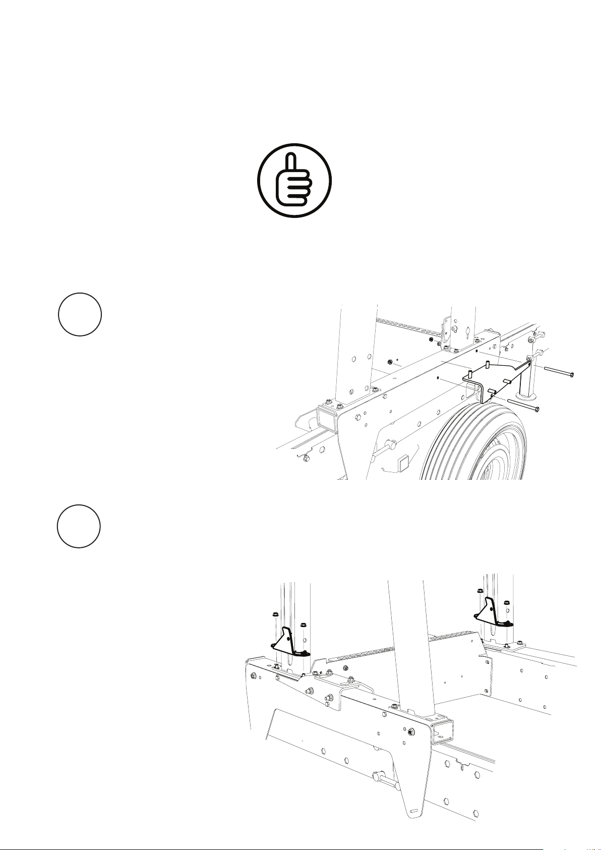
ASSEMBLY
1
TRAILER KIT
Good job!
Now it is time to install the sawhead locking mechanism.
Fit the sawhead lock to the bogie tube.
Repeat this step on the other bogie tube.
2
Fit the lower sawhead lock mounts to the
bottom plates of both the sawhead bogie
legs. Be careful when loosening the bolt
joints; the bolts can easily fall out of the
square tube on the underside.
17
Page 18
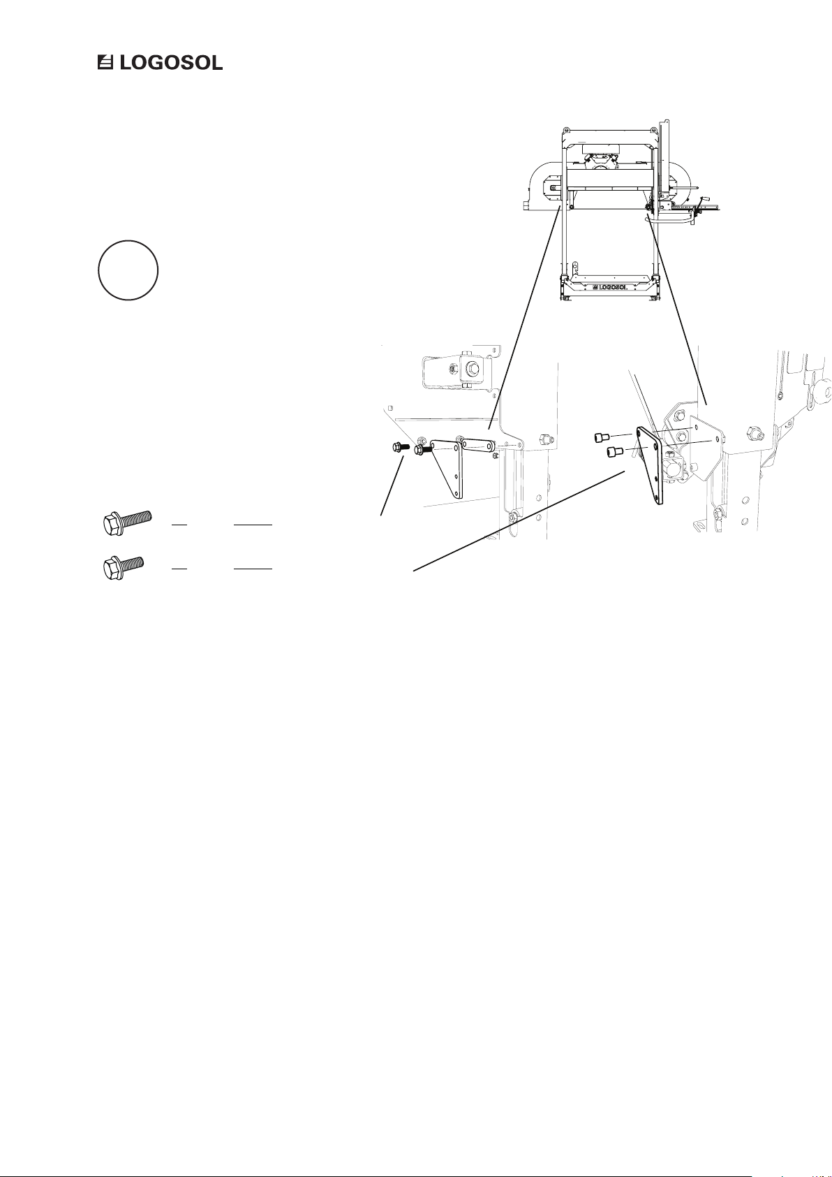
ASSEMBLY
3
Fit the top mounts to the sawhead bogie legs.
Note that the mount on the exhaust side of
the sawhead has to be tted with a spacer
between it and the bogie leg.
2x
2x
Flange bolt M8x25
Fiange bolt M8x20
18
Page 19
FUNCTIONS
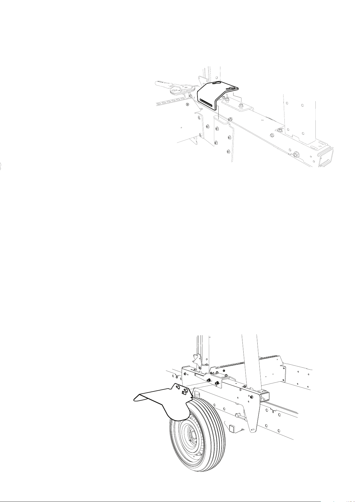
LOCKING THE SAWHEAD
Secure the sawhead with the lock bracket before
transport.
TRAILER KIT
FENDERS
Fit the fenders to the attachment plates before
transporting the sawmill.
19
Page 20
FUNCTIONS
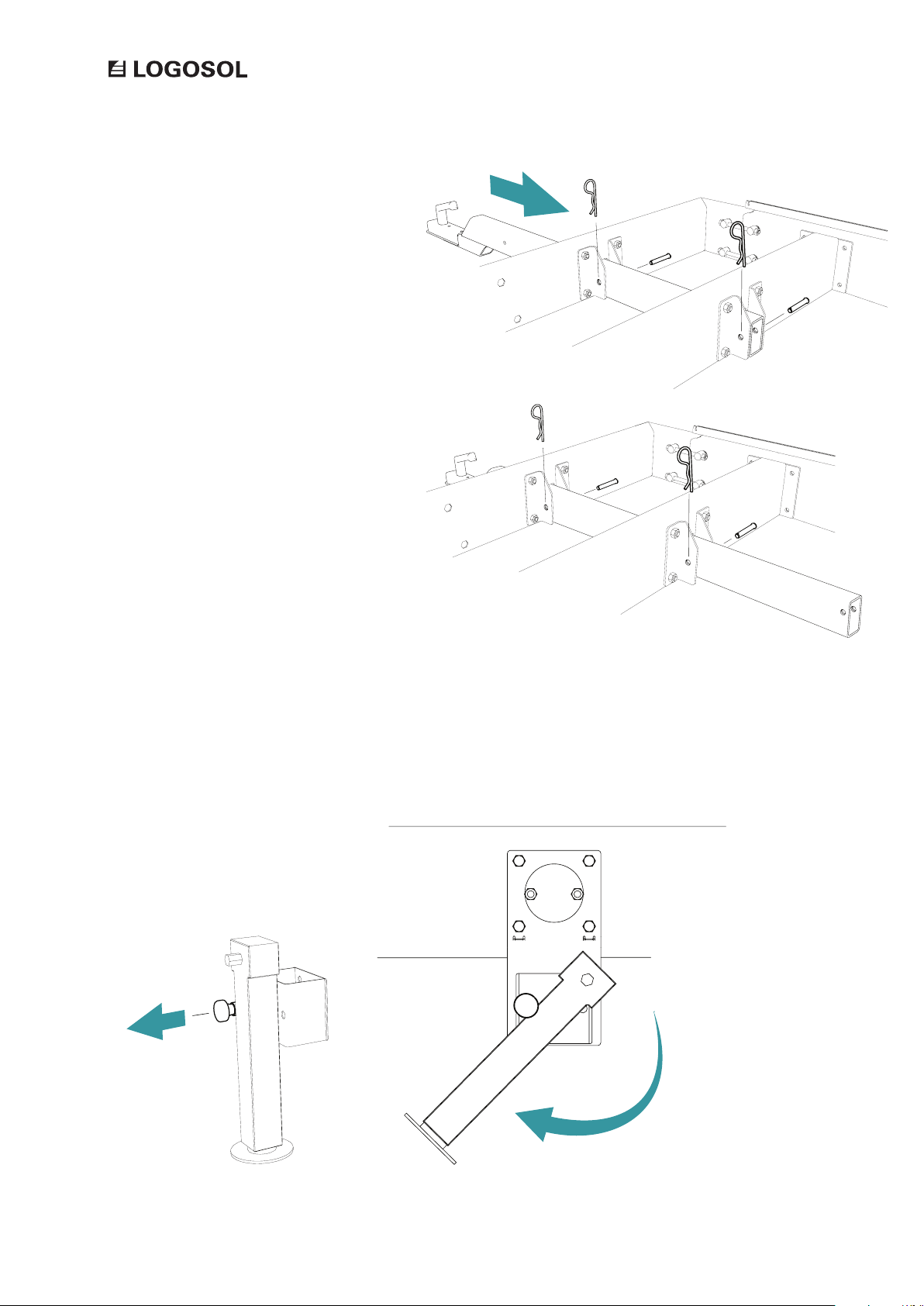
THE POSITIONS OF THE DRAWBAR
The trailer drawbar can be set to two positions. It
can be pulled out for transport, and pushed back for
a better access around the sawmill.
SUPPORTS LEGS
The trailer support legs can be folded
up during transport. To fold up the
legs, you pull out the lock pins.
20
Page 21

Page 22

Page 23

Page 24

 Loading...