

Page 1
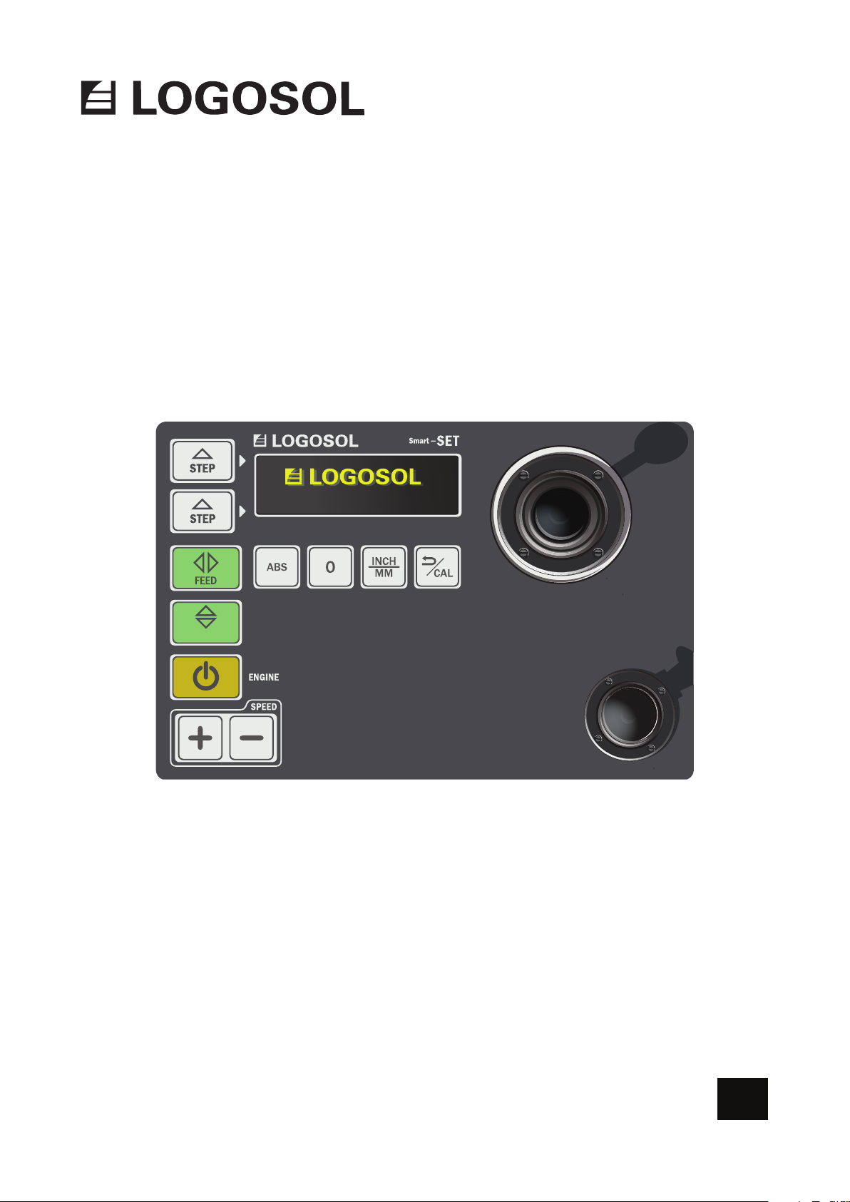
USER MANUAL
Ref. no. 0458-395-5352
/
UP DOWN
SMART SET
AUTOMATION
EN
Page 2

THANK YOU FOR CHOOSING A LOGOSOL MACHINE!
We are very pleased that you have demonstrated your condence in us by purchasing this
product, and we will do our utmost to meet your expectations.
Logosol has been manufacturing sawmills since 1989. In that time we have supplied
approximately 50,000 machines to satised customers the world over.
We care about your safety as well as we want you to achieve the best possible results with
your equipment. We therefore recommend that you take the time to carefully read this user
manual from cover to cover in peace and quiet before you begin using the product.
We hope you get a lot of satisfaction from the use of your new equipment.
Bengt-Olov Byström
Founder and chairman,
Logosol in Härnösand, Sweden
Read through the user manual carefully
and make sure you understand its
contents before you use the equipment.
This user manual contains important
safety instructions.
WARNING! Incorrect use can result in
serious or fatal injuries to the operator
or others.
LOGOSOL continuously develops its products.
For this reason, we must reserve the right to modify
the conguration and design of our products.
Ref. No. User Manual, English: 0458-395-5352
Document: Smart Set User Manual
Text: Martin Söderberg
Illustration: Martin Söderberg
Last revised: January 2019
© 2018 LOGOSOL, Härnösand Sweden
Page 3

TABLE OF CONTENTS
Safety instructions 4
Start and stop 6
Functions 7
Page 4
SAFETY INSTRUCTIONS
KEY TO SYMBOLS
WARNING! This symbol means that you
should pay particular attention and is always
followed by information about the relevant
risk.
This symbol is followed by important
information or instructions. Pay particular
attention when this symbol appears in the
manual text.
For your own safety and the safety of others,
do not use the equipment without rst
having read and understood all the contents
of this user manual.
WARNING! Cutting tools: Incorrect use can
lead to life-threatening injuries. Band blades
are extremely sharp and dangerous.
Always use protective gloves (class 1) when
working with the band sawmill or handling
band blades. Risk of sustaining cuts when
handling band blades. Band blades and
engine parts can be hot after sawing.
Always use approved hearing protection
when working with the machine. Even
short exposure to high frequency noise
can damage your hearing. Always use
closetting safety goggles when working
with the machine or handling band blades.
Under certain circumstances the use of
respiration protection may be necessary. This
would mainly apply if you are sawing dry
wood or sawing indoors.
Always wear approved protective footwear
with saw protection, steel toe-caps and
nonslip soles when working with the
machine or handling band blades.
Always wear full-length protective trousers
when working with the machine or handling
band blades. Never wear loose-tting
clothing, scarves, neck chains, etc., that can
get caught in the machine during operation.
Secure loose hair before working with the
band sawmill.
4
Page 5
SAFETY INSTRUCTIONS
THE SAFETY EQUIPMENT OF THE
BAND SAWMILL
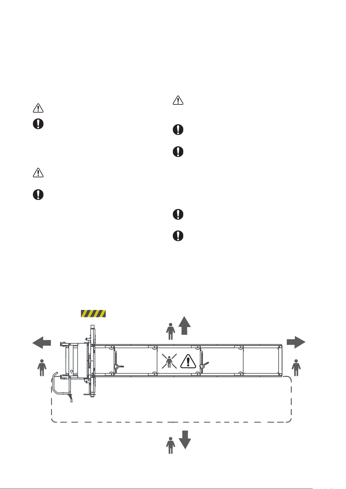
WARNING! Risk of serious injury.
Read the safety instructions for the sawmill
in its user manual, 0458-395-5301, before
using the machine. Pay particular attention to
the safety distance for other persons than the
operator [Illustration 1] as the automation of
the machine increases the risk of injuries.
WARNING! Never use the machine if the safety
equipment is defective.
The safety equipment must be checked and
maintained.
Here is a description of the safety features of the
Smart Set control, and their functions.
Emergency stop on the control unit
On the control unit there is an emergency stop that
shuts off both the control panel and the engine.
OPERATOR
WARNING! Whenever the machine is used,
approved personal protective equipment must
always be used.
Persons under the age of 18 may not work
with the band sawmill or handle band blades.
Never work with the machine or handle band
blades if you are tired, if you have consumed
alcohol or if you are taking medication that can
impair your vision, judgement, reaction times,
mobility, alertness or otherwise cause negative
side effects.
THE WORKSITE
Always keep an ABC re extinguisher
(min. 3 kg) easily accessible at the worksite.
Always keep a fully-stocked rst-aid kit easily
accessible at the worksite.
Enabling switch on the control panel
The eneabling switch is a lock between the operator
and the control panel. To be able to run the software,
the enabling switch button has to be pressed down.
5M
Illustration 1.
15M
5M
5M
5
Page 6

START AND STOP
START
1. Open the fuel valve by moving the fuel control
lever to the right until it reaches the position ”ON”.
2. To start a cold engine, move the choke control
lever to closed position (the control lever in its left
position). To start a hot engine, leave the choke
control lever in its open position (the control lever in
its right position).
3. Turn the ignition key to the ”ON” position and
start the engine with the key.
4. With the software running, press the start button
at the same time as the enabling switch button is
being pressed down.
5. This brings the engine up to its operating speed
and the band blade starts rotating.
6. If the choke is in its closed position, gradually
move the control lever towards its open position as
the enging gets hotter.
STOP
You stop the band blade by releasing the control
lever or the enabling switch button. Then the band
blade will stop and the engine will go to idle. After
that, turn off the engine by turning the ignition key
to the”OFF” position, and then close the fuel valve.
EMERGENCY STOP
Activate the emergency stop by pressing the
emergency stop button. The emergency stop has to
be reset after it has been used.
6
Page 7
FUNCTIONS
The control unit
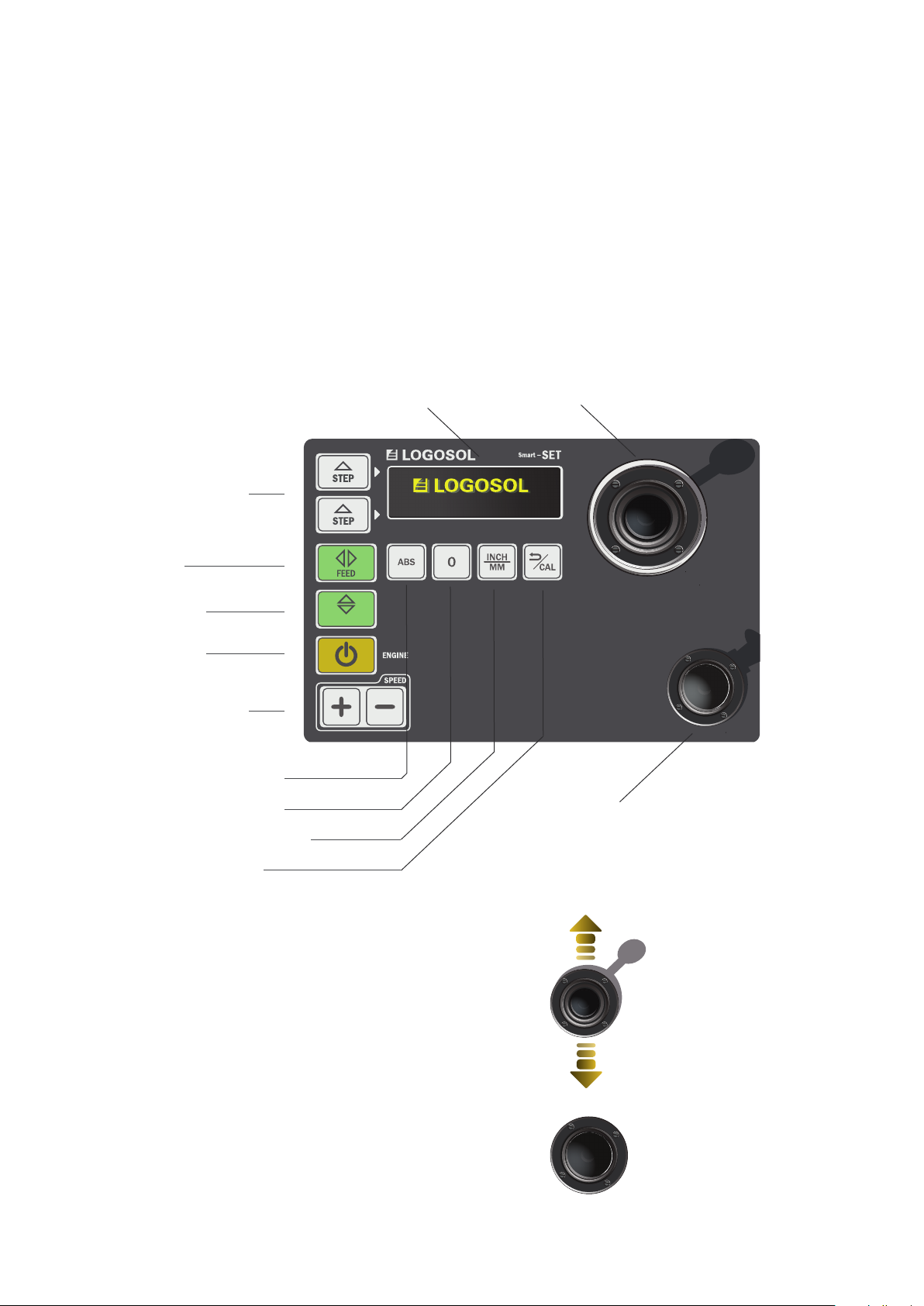
The control unit of the Logosol Smart Set has a display, a set of programs, setting keys, an enabling switch
button and a control lever. To use a function you select the desired one on the control panel. Then, to be
able to execute the command, the enabling switch button has to be pressed down at the same time as the
operation is carried out by the control lever. If the enabling switch button is released, the machine will stop.
Sawing dimensions
Feed
Up/Down
Start engine
Feed rate
Absolute measurements
Relative measurements
Measurement unit, inch/mm
/
UP DOWN
Display
Control lever
Enabling switch button
Calibration, cancel
Control lever
The control lever of the Smart Set control unit
is progressive, i.e. it performs operations at an
increasing rate depending on how far from the
centre it is pushed.
Enabling switch button
The enabling switch button is a safety function. It is
superior to the control unit and has to be kept pressed
down if the machine is to be activated.
The control lever is only
used in the directions
forward/back.
7
Page 8
FUNCTIONS
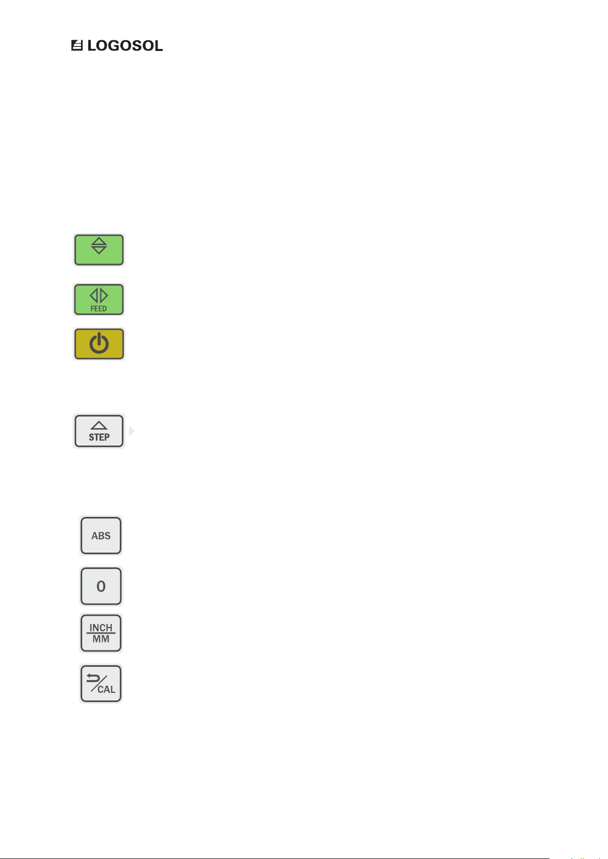
PROGRAM KEYS
/
UP DOWN
SETTINGS
Up / Down
Sawhead position /
Start
REV UP ENGINE
STEP MODE
ABS
Up / Down activates the ability to move the sawhead
vertically.
The feed key is used for running the sawhead back and
forth over the rails.
Activates the engine to enabling sawing operation. The
engine revs up and then runs at working rpm until the
control lever is released.
Step mode is two adjustable modes that enable you to
quickly repeat a preset value of the saw cut.
Absolute measurements means that the display will
show the distance between the bottom of the sawblade
and the top of the log bed.
0
MEASUREMENT
UNIT
CAL / Back
The 0 key creates a zero point for the position of the
sawhead. The value shown on the display will then start
out from this point.
The display can show measurements in inches or
millimetres. To choose measurement unit you press the
key inch/mm.
This key activates the calibration function of the
machine.
8
Page 9
FUNCTIONS
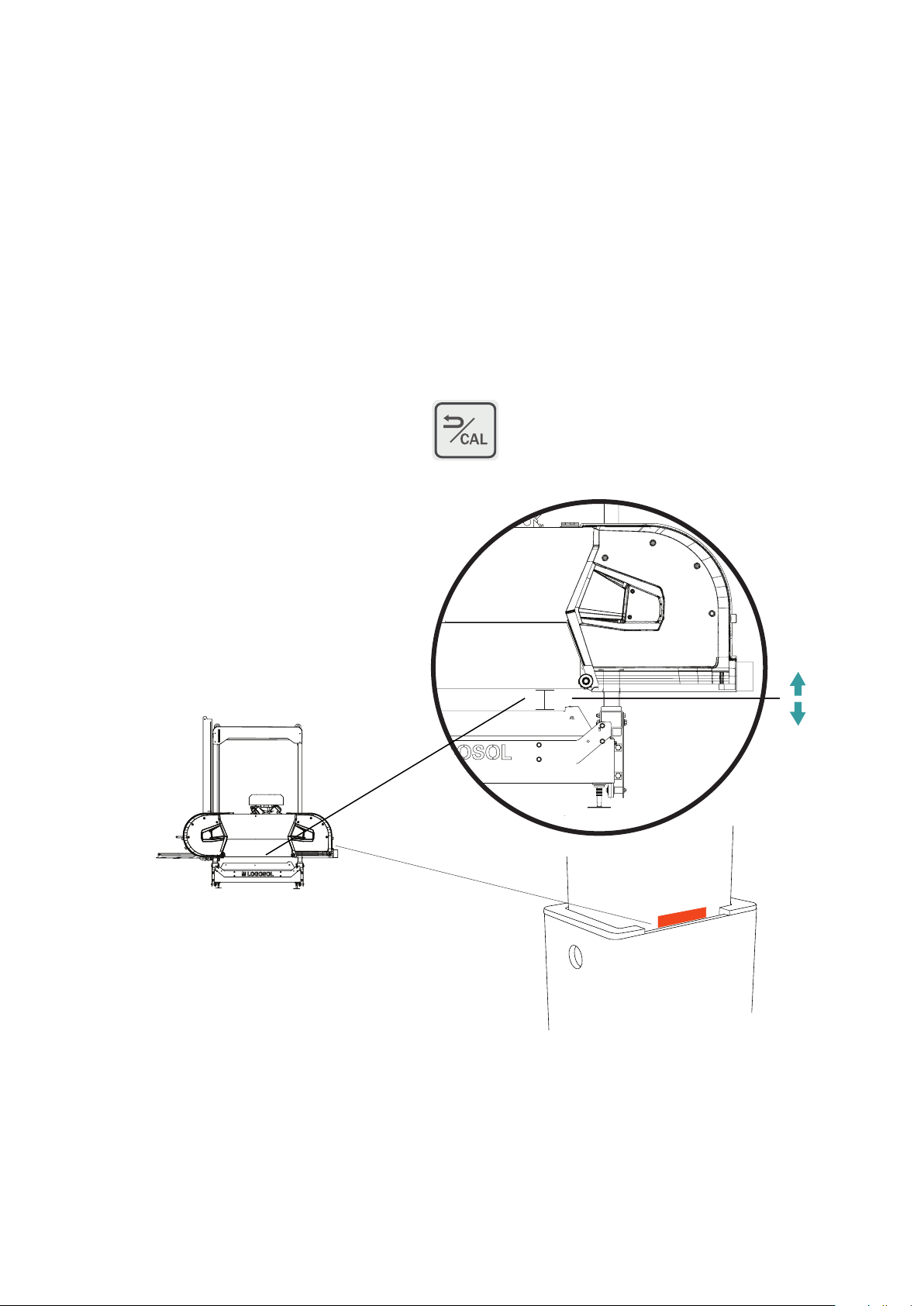
Calibration
At each start-up, the machine asks for the measurement between the sawblade and the log
bed. If the value shown on the display does not agree with the value on the machine scale, the
calibration value has been changed and the machine has to be recalibrated. This operation is
carried out in the calibration mode.
CALIBRATION
If you, during operation, suspect that the value
on the display does not agree with the actual
position of the sawblade, you can use the
Cal key to put the machine in the calibration
mode. The Cal key is pressed down to start the
calibration. Then, you move the sawblade with
the control lever until it comes to the calibration
value 100 mm from the log bed. Be careful when
measuring the position of the saw blade. The
precision when positioning the saw blade will
directly reect the accuracy of the dimensions of
the sawn timber.
100MM
One tip is to put a mark for the calibration
position on the bogie leg after your rst
calibration. This will facilitate when making
rough adjustments when it is time for the next
calibration.
9
Page 10
FUNCTIONS
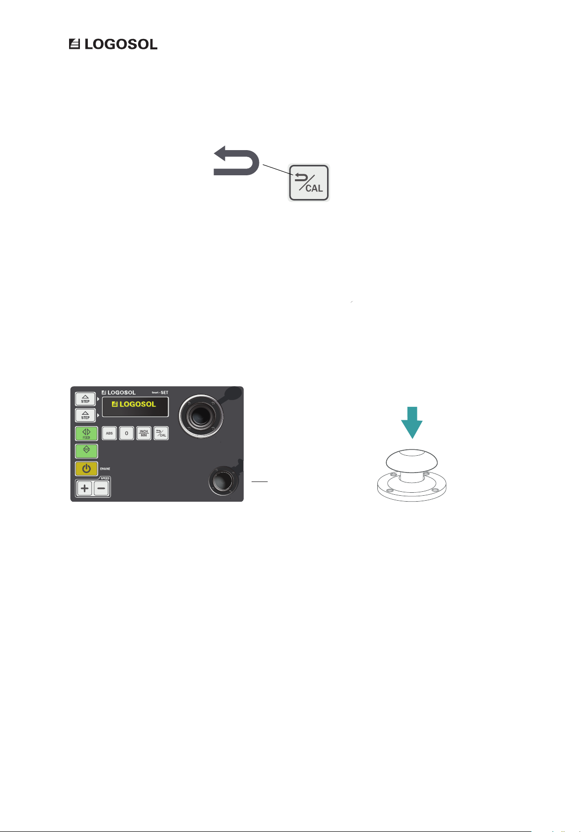
CANCEL COMMAND
The calibration key has two functions; it also works as a command for cancelling a
selected operation. Pressing this button returns the machine to standby mode.
ENABLING SWITCH BUTTON
The enabling switch button is the big button located below the control lever to the
right of the control panel. The enabling switch is connected to all the functions of the
machine and is to be regarded as a lock between the keypad and the control lever.
To execute the selected command, the enabling switch button has to be kept pressed
down.
/
UP DOWN
ENABLING SWITCH
BUTTON
10
Page 11
FUNCTIONSFUNCTIONS
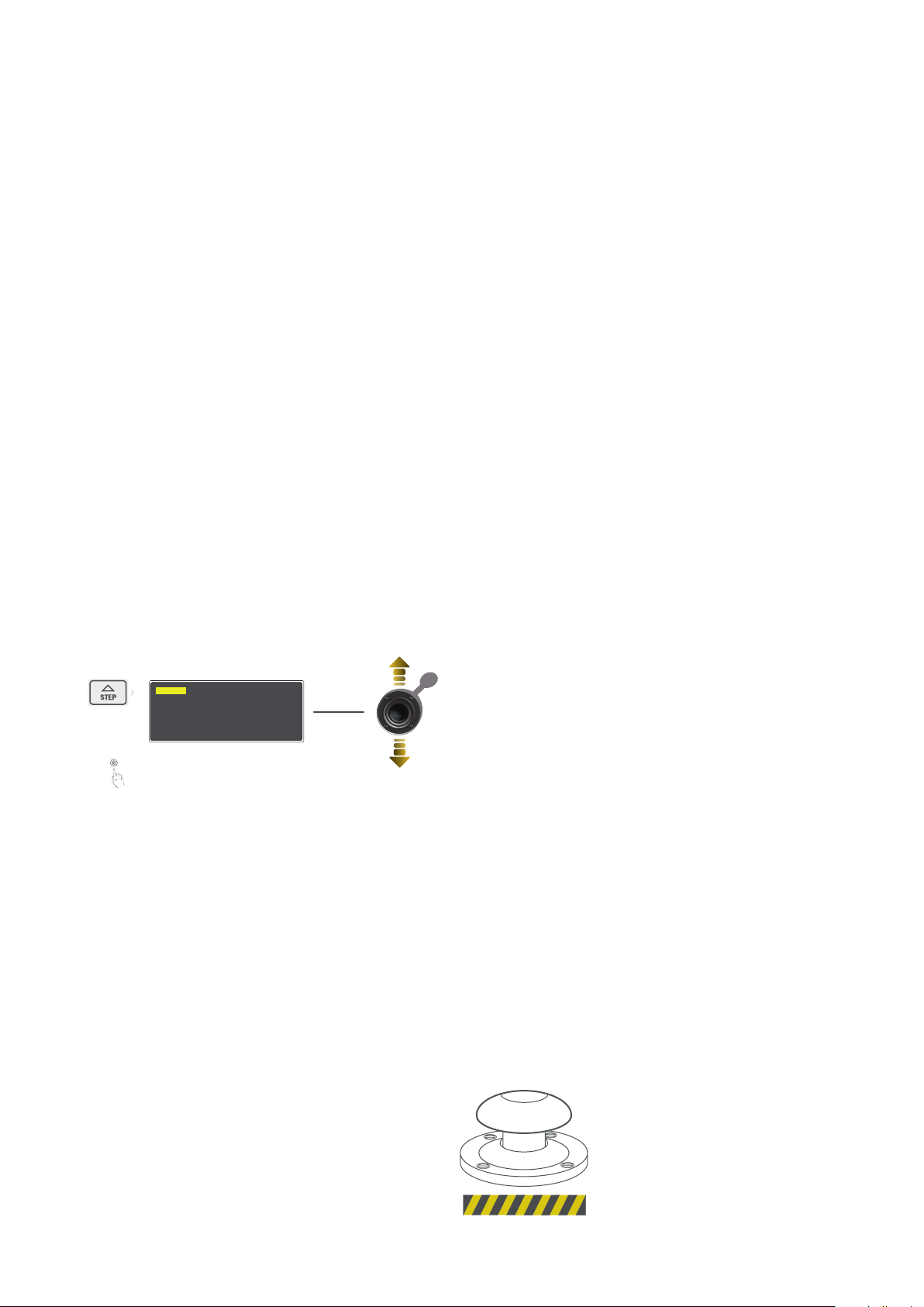
STEP MODE
Step mode is two adjustable modes that enable you to quickly repeat a preset value of
the saw cut. When you use Step mode, the machine remembers where the sawhead was
positioned when the last cut was made. This means that the sawhead will be lowered to
the position of the last cut plus the selected value. The movements are kerf-compensated,
i.e. if you use a preset value of 25 mm, the sawn board will be 25 mm. The saw head has
then actually moved 25 mm + 3 mm = a kerf-compensated, 25 mm board.
SETTING STEP MODE
Set the Step mode by pressing down one of the step keys. This has
to be done with the Smart Set in its standby mode. Keep the sawing
dimension key pressed down and then enter the desired value using
the control lever. The value will be shown on the display next to the
key to which the relevant command is connected.
25.5 0
STEP MODE
HOLD
USING STEP MODE
The Step mode is activated by pressing one of the preset step keys. The value will then
be shown on the display. To activate the command, you push the control lever forward.
Now, the sawhead is lowered down to the position of the previous cut plus the selected
value. This means that you can make a cut, raise the sawhead to be able to bring it back
over the sawn board, and then use the step function to move the sawhead and cut a
new board with exactly the same measurements as the last one.
TURNING OFF THE SMART SET
When the work is nished, the machine is
switched off by pressing the emergency stop
button on the top of the control unit.
11
Page 12
FUNCTIONS
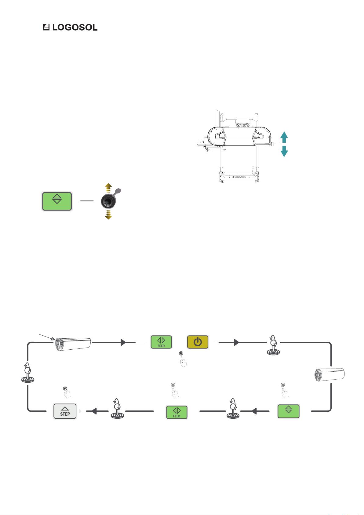
UP / DOWN
The Up / Down key is used for activating the ability
to move the sawhead vertically with the help of
the control lever. In the basic mode, the position is
shown as a value on the dispaly. This value shows
the distance between the sawblade and the log bed.
/
UP DOWN
CUTTING A LOG
The illustration below shows an examaple of a
workow, with the steps that are performed by
the Smart Set during sawing.
START POSITION
To make a cut, begin by setting the
sawblade to the desired height.
HOLD
Prepare the next cut by using a preset
depth of cut. Keep the Step key pressed
down while using the control lever.
Activate the feed and start the engine to
enable sawing.
Activate the feed and bring the
sawhead back to the start position.
Feed the blade through the log using
the control lever.
/
UP DOWN
Activate Up / Down to be able to raise
the sawhead before bringing it back.
12
Page 13
FUNCTIONS
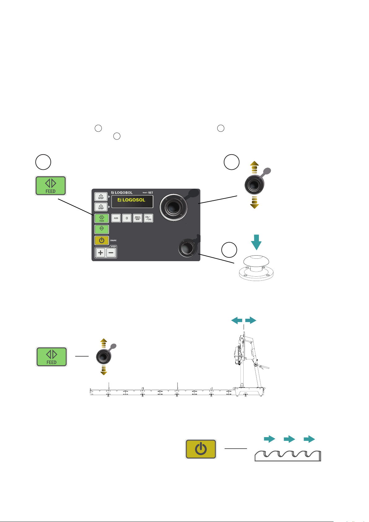
PERFORM FUNCTIONS
To be able to run the different functions in Smart Set, you follow the steps as shown in
the illustration below. Select the desired function on the keypad, Keep the enabling
switch button pressed down. Carry out the selected operation with the help of the
control lever. If you release the enabling switch button, the operation cannot be performed.
1 2
3
1
/
UP DOWN
FEED
The feed function is used for moving the sawhead back
and forth over the rails. This function is acativated with
the Feed key, and is then controlled by the control lever.
Remember that the enabling switch button has to be kept
pressed down to enable the movement.
3
2
REVVING UP THE ENGINE
To rev up the engine and start the blade,
you have to be in the Feed mode and then
press down the Start key. Stop the engine by
releasing the control lever to its 0 position.
13
Page 14
FUNCTIONS
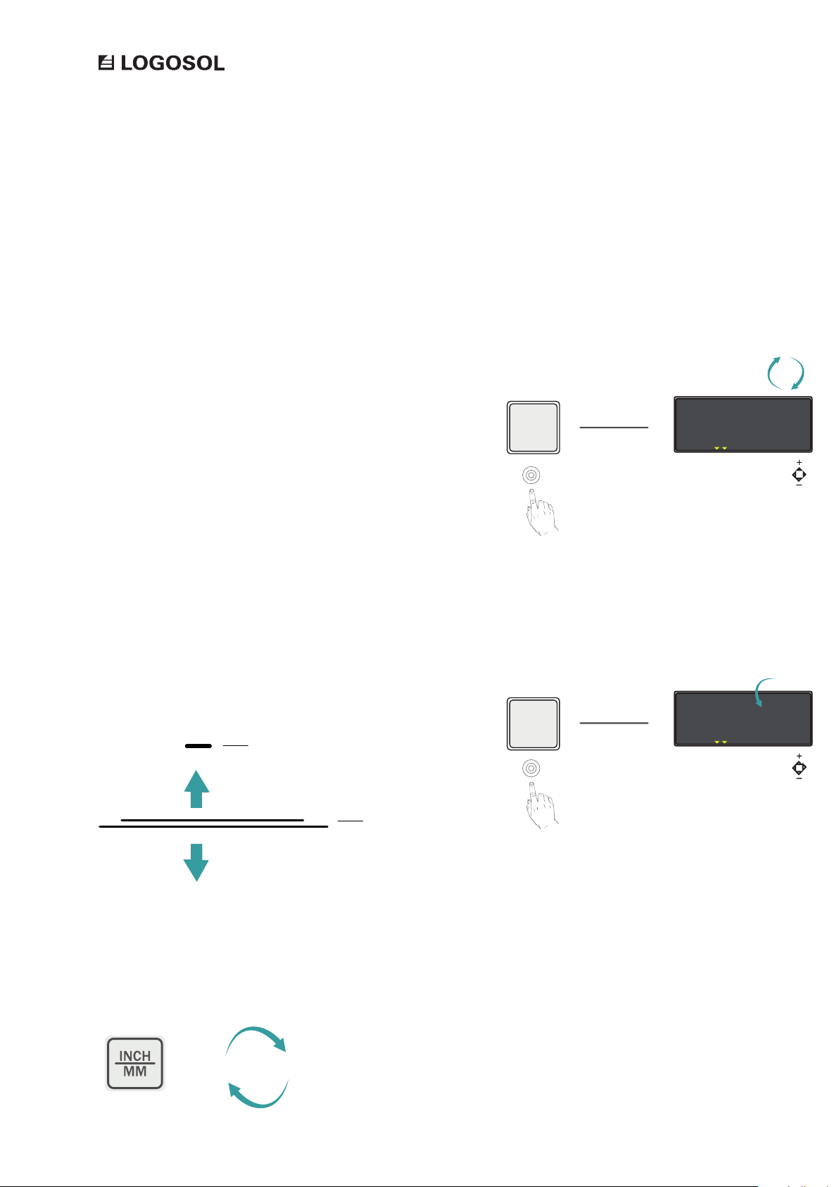
SAWING DIMENSIONS
The Smart Set interface can show different sawing dimensions and
units to facilitate for the user in different situations. The default
setting of the interface is showing an absolute measurement between
the sawblade and the log bed in millimetres.
ABSOLUTE MEASUREMENTS
The Smart Set interface initially shows the distance between
the log bed and the bottom of the sawblade. The selected
measurement is shown in the box called ABS on the display.
RELATIVE MEASUREMENTS
The 0 key creates a new zero point for the log bed position. From
this zero point, a new relative measurement is shown for the position of the log bed. If the sawblade is raised from this selected point,
a negative value is shown, and if the sawblade is lowered a positive
value is shown. On the display, the selected value is shown with the
symbol 0. In this mode, the kerf is compensated manually.
If the saw blade position is raised
from the set zero point, the value
shown on the display is negative.
ABS
0
10.00
10.00
MM
10.00
10.00
MM
100.00
TOE BOARD
1 2 3 4 A B C
0.00
TOE BOARD
1 2 3 4 A B C
REL
ABS
0
14
0
INCH/MM
The display can show measurment units in millimeters or
inches. To select measurement unit, you press down the
Inch/mm key.
INCHMM
Page 15

15
Page 16

 Loading...