

Page 1
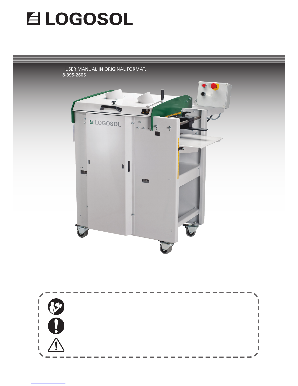
USER MANUAL
LOGOSOL SH410
Read through the user manual carefully and make sure you understand its contents
before you use the machine.
This user manual contains important safety instructions.
WARNING! Incorrect use can result in serious or fatal injuries to the operator or others.
TRANSLATION OF USER MANUAL IN ORIGINAL FORMAT.
ARTICLE NO: 0458-395-2605
Page 2
2
Welcome! We are very pleased that you have
demonstrated your condence in us by purchasing
this machine and we will do our utmost to meet
your expectations.
Logosol has been manufacturing wood processing
machinery since 1988, and in that time we have
supplied approximately 30,000 machines to satised
customers all around the world.
We are concerned with your safety and ensuring
that you achieve the best possible results with your
planer. We therefore recommend that you take the
time to carefully read this manual, from cover to
cover in peace and quiet, before you begin sawing.
Remember that the machine itself is just a part of
the value of the product. Much of the value is also
to be found in the expertise we pass on to you in
the user manuals. It would be a pity if that were not
utilised.
We hope you get a lot of satisfaction from the use of
your new machine.
Bengt-Olov Byström
Founder and chairman,
Logosol in Härnösand, Sweden
Thanks for choosing
a Logosol machine!
LOGOSOL continuously develops its products.
For this reason, we must reserve the right to modify
the conguration and design of our products.
Text: Bo Mårtensson, Mattias Byström
Document: Logosol SH410 Manual
Pictures: Bo Mårtensson, Lars Wahlström
Last revised: May 2018
Manual, part no.: 0458-395-2605
© 2011 LOGOSOL, Härnösand, Sweden
#2
Page 3

3
Table of contents
Safety rules 4
Safe distances 5
Required tools 6
Description of machine 6
Shavings handling 7
Summary 8
Electrical system 10
Wiring diagram 11
Cuts using planing knives, moulding
knives and circular sawblade 13
Planing knives 14
Moulding knives 15
Replacing circular sawblade 16
Maintenance 17
Feed 17
Installing feed tables 18
Four functions 21
Planing tips 21
Good to know 22
Safety regulations for moulding
knives 24
Starter package SH410: moulding
knives & examples of combinations
25
Technical data 28
EC DECLARATION 31
LOGOSOL SH410
Page 4
4
SAFETY INSTRUCTIONS
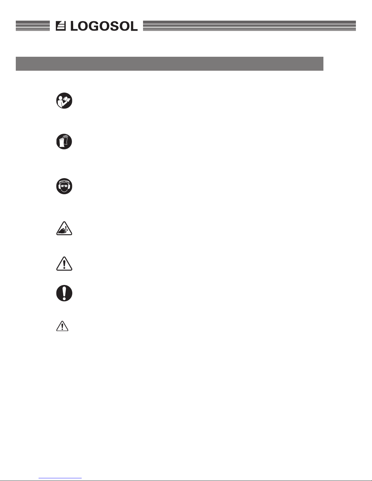
KEY TO SYMBOLS
For your own safety, read through the user
manual carefully and do not start the machine before you have understood everything. Do not let persons who have not read
the manual, use the machine.
Risk of cut injuries. Use protective gloves when
you handle knives and circular sawblades. It
is particularly important to wear gloves when
opening or tightening the knives' locking
screws (the tool can easily slip).
Use approved ear protectors. Hearing can
be damaged by just short exposures to high
frequency noise. Use approved protective
eyewear. Splinters and wood pieces can be
thrown out with great force during processing.
Warning for cutting tools. Never place your
hands or tools above or below the planing
table or in the the shavings ejector when in
operation.
This symbol means 'WARNING!'. Pay particular attention where this symbol appears
in the manual text.
A warning comes after this symbol. Pay particular attention where this symbol appears
in the manual text.
WARNING! The planer can cause serious body
injuries where incorrectly operated. Make
sure you are therefore fully concentrated on
the operation of the unit and are very careful
when you use the machine.
Never stand in the path of a board. The board
can be thrown backwards and out of the machine.
Branches, splinters or pieces of metal can also be
thrown out at great speed. Always stand beside the
in-feed table.
Only one work piece at a time is to be fed
through the machine.
Make sure that the machine is set so that the feeder
rollers (5*) grip the workpiece. Do not feed in work-
pieces which are so conical that there is a risk that
the feeder rollers can lose their grip. Never place
your hands or tools above or below the table when
the machine is running.
Before the machine is started:
• Check that the cutter can rotate freely and that
no tools or loose components have been left in
the machine.
• Check that the cover is properly closed and
that the cover‘s two locking screws have been
tightened
• Check that all knobs, bolts, nuts, stops, shavings
guides, cutters, knives, circular sawblade protective covers, in-feed and out-feed tables etc. are
properly tightened, that the shavings hoses are
tted and that the chip extractor is switched on.
'Shut off the power' means that the cable with
the CCE contact, which supplies the machine with
power, is disconnected from the machine and is
placed in such a way that no unauthorised persons
can re-connect it. The cable is to also be placed so
that there is no risk that it can be treaded upon or
tripped over.
Shut off the power by pulling out the contact and
waiting until the cutter has stopped:
• before you open the cover to replace knives,
replace circular sawblade,
• clean or carry out other work on the unit, above
or below the surface of the table.
• before you replace belts or carry out other service or cleaning work.
• before the machine is moved.
• if the machine is to be left unattended.
The shavings hose and chip extractor are to be connected to the shavings ducts and are to be securely
fastened such as by using hose clips.
Do not wear loosely hanging clothes or anything
else which can get caught up in the machine's moving parts. Fasten long hair up in a secure (and nice)
way.
Never use the machine under poor visibility conditions. Always work under good lighting.
Do not use the machine if you are under the inuence of alcohol or other narcotics or medicines.
Page 5
5
LOGOSOL SH410
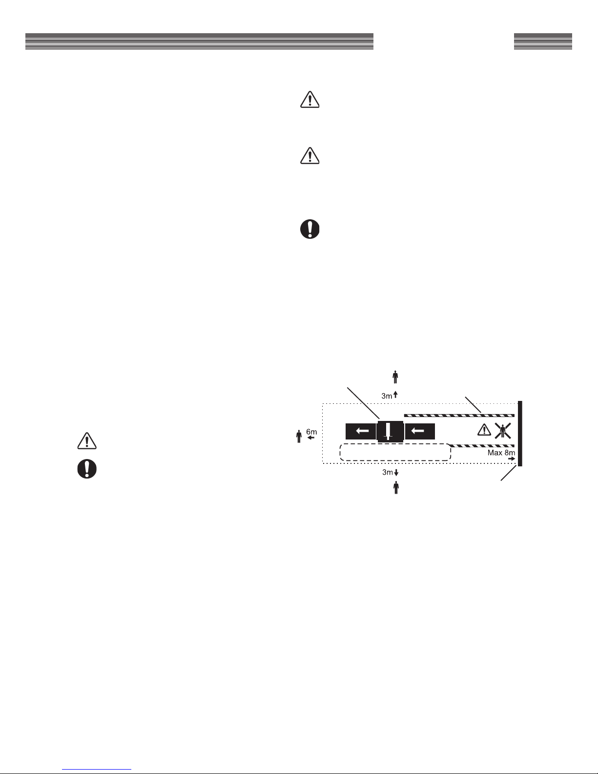
SAFE DISTANCES
No-one other than the operator is to be
present within 3 metres of the sides of the
machine or 6 m from the out-feed side when
in operation. There is to be a wall or other
barrier on the in-feed side, which stops any
thrown-out materials. The wall or barrier is to
be maximum 8m from the machine, but ideally closer if short work pieces are processed.
Set up a form of cordoning which prevents
persons unintentionally entering the risk area
between the machine and the barrier on the
in-feed side.
Keep the workplace clean and tidy. Do not place
anything on the ground which you can later trip
over.
Never place your hands or any tools on the planing
table when the machine is running.
Do not climb onto the machine.
Do not tread on the machine's electric cable.
Make sure that the machine is positioned in such
a way that access to the emergency stop is not
blocked.
For greatest electrical safety, use a residual current
device.
The machine is not to be modied and is not to be
added to. Only use original parts supplied by Logosol
which are designed for the purpose. After service,
the machine should be in its original condition.
The machine's warning markings are there for your
own and other's safety. Damaged or illegible labels
are to be replaced.
Blunt circular sawblades or knives increase the risk of
accidents.
WARNING! Risk of rebound.
The minimum permitted workpiece length:
300 mm. Make sure that you are familiar with
all functions and settings options before you
begin using the machine.
External environment: The motors and the electrical system can be damaged if the machine is stored
or is used at temperatures below zero degrees C
or if it is stored in damp unheated environments.
Water can condense and collect in the motors and
the electrical system's housing, i.e. the control panel
(this applies to most sealed motors). There is a drain
plug on each motor which can be removed to check
that the motor is dry inside. Also check that water
has not collected in the control panel. This check
should be carried out regularly where there is a risk
of condensation.
Operator working area
Barrier behind infeed side
Cordoning
SH410 with in-feed and
out-feed table
Risk
area
WARNING! The circular sawblade has only
two positions on the blade shaft. The locking
screw is to always be fully tightened in one of
the shaft's two countersinks.
WARNING! The circular sawblade is to only
be used on workpieces of thicknesses of less
than 77 mm.
Page 6
6
DESCRIPTION OF MACHINE
REQUIRED TOOLS
The SH410 Solo planer/moulder is a wood dimensioning machine which can process two sides of a
workpiece or, in some cases, three sides.
The machine is designed around a solid rack and a
plane table of steel plate. The table is suspended in
the rack by twin parallel stays, which allow the table
to be safely raised and lowered using a lever.
The workpiece is fed horizontally onto the plane
table and through the machine by two feeder rollers. The feeder rollers are spring mounted and tted
to the rack. The workpiece is steered laterally by an
adjustable stop and a sprung press roller.
Pieces are processed by a cutter and a circular sawblade. The cutter and the circular sawblade counter
rotate and are driven by a powerful electric motor
which transfers drive by a poly-v-belt transmission.
The cutter and feeder rollers are covered by a retractable protective hood. A safety switch prevents
the machine from being started if the hood is not
locked.
The machine is tted with throw-out protection on
the in-feed side.
Siting
Check the Solo planer/moulder on receipt. Any
transport damage is to be immediately
reported to the transport company.
Most of the planer is rust protected and therefore
can withstand being placed in cold spaces. Additional maintenance in the form of the lubrication of the
components without rust protection is however
required. Refer to the 'Maintenance' and 'lubrication
points' sections.
• There is to be an open space below the machine, so that shavings cannot collect around
the motor. Also screw the planer into place
through the holes in the rack's underside.
• Make sure that there is sufcient unrestricted
space for the longest boards which are to be
planed on the in-feed and out-feed side and
that there is space for service and wood storage.
• Hang planer electrical cables from the roof or
protect them in other ways. Never tread on the
cable. The machine should be connected via a
residual current device.
• Make sure that there is very good lighting. There
is to be good general lighting. Also set up a
powerful lamp right above the machine. Make
sure that there is no risk of being blinded by the
light.
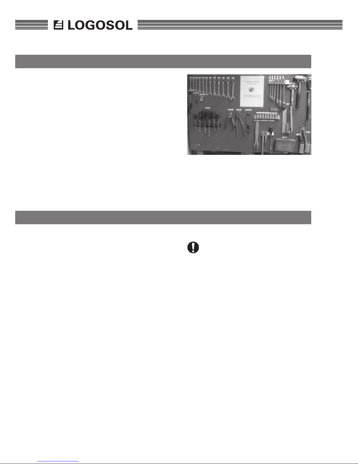
TIP! Make a tool board for the tools you need and
set it up alongside the planer, so that you can easily
see it. Look at tool board before you start the machine to check whether any tools are missing. They
could have been left in the machine!
• 10 mm spanner
• Allen key 3 mm
• Allen key 4 mm
• Allen key 6 mm
• Ring spanner 13 mm
• Ring spanner 10 mm
• Adjustable spanner
• Setting block for planing knives
• Callipers
• Guide rail 30-50 cm
Page 7

7
LOGOSOL SH410
SHAVINGS HANDLING
The Solo planer/moulder is to be connected to a chip
extractor which has a capacity of minimum 1000
m3/h. Logosol has a very suitable 240V 2-phase,
1.5kW fan.
The re risk and dust emissions (releases) associated
with shavings collection must be taken into consideration.
WARNING! Fire risk and dust emissions associated with shavings handling.
Contact the local authorities for advice on the
regulations which apply in your area.
• Connect the shavings hose and attach it, using
hose clamps, to both the planer and the chip extractor. Use Flexislang from Logosol (L:3m, part.
no: 7000-000-1015) which has a smooth inside
and which improves ow.
• If you want to transport the shavings across a
longer distance:
Use the shortest hoses possible and
transport the shavings in sheet steel pipes which
generate less resistance to air ow.
• The shavings duct on the cover can be unscrewed, removed and turned so that hose connection is to the right or left.
Position the chip extractor so that its switch is
easily accessible.
In-feed and out-feed table
Logosol can supply in-feed and out-feed tables. You
can also build your own in-feed and out-feed table
yourself. It is very important that the in-feed table,
planer table and out-feed table are precisely in-line,
so that the cutter does not leave marks on the ends
of the workpieces.
Page 8
8
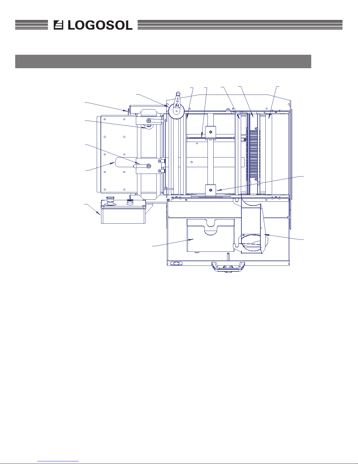
SUMMARY
0
1
2
1
1
2
3
4
5
6
7
7
8
9
1
1
1
3
Art.nr
Pos. Description Part no.
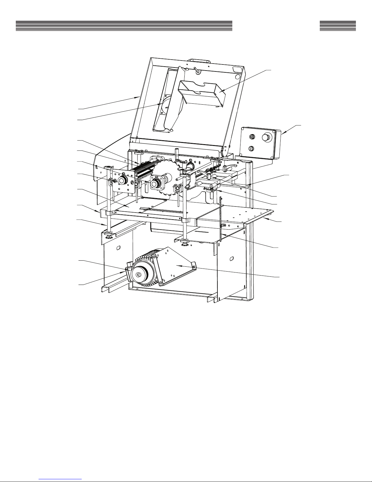
1 Control panel 7504-0002 Stop 7504-0003 Locking of stop 7504-0004 Press roller cpl 7504-0005 Height scale 7504-0006 Crank 7504-0007 Ribbed feeder roller 7504-0008 Blade 7504-00010 Out-feed roller PU 7504-00012 Duct, planer cutter 7504-00013 Duct, blade 7504-00014 In-feed table 7504-00015 Spindle motor 7504-00016 Motor pulley 7504-000 Poly-v-belt 7504-00017 Motor stand 7504-000 Hoist spindle 7504-000 Hoist spindle crank
18 Table 7504-00019 Plastic lining 7504-00020 Pulley cutter 7504-00021 Pulley blade 7504-00022 Protective cover 7504-000-
Page 9
9
LOGOSOL SH410
1
2
3
4
5
14
15
16
17
17
18
19
20
21
8
9
12
22
13
1
2
3
4
5
14
15
16
17
17
18
19
20
21
8
9
12
22
13
Page 10
10
THE ELECTRICAL SYSTEM
WARNING! Lethal voltage. Do not, at any
point in time, open the machine's electrical
system unless you are authorised to do so.
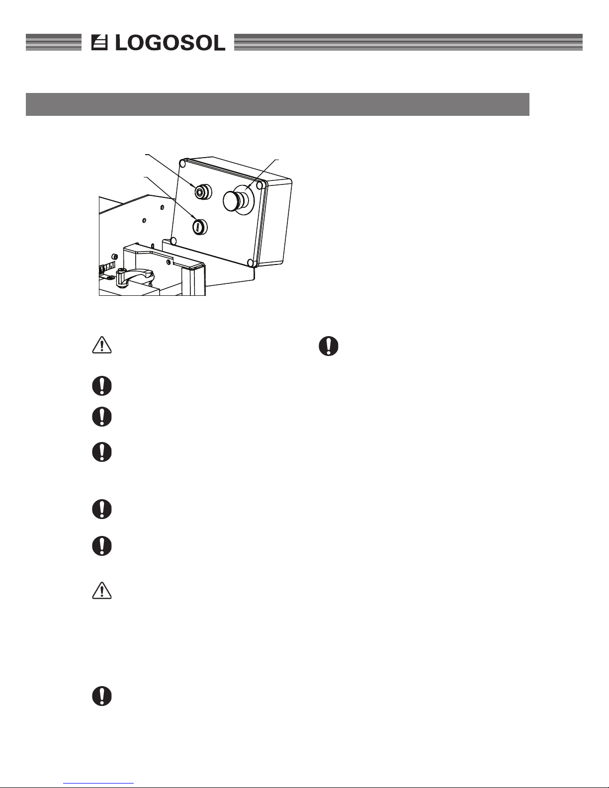
The black button starts the machine, pos 3.
The red button stops the machine,
pos 2.
The red emergency stop button is only to be
used to stop the machine in an emergency
situation, pos 1. Access to this switch must
not be blocked.
Carry out the 'Before the machine is
started'check, refer to the safety instructions.
Check that cables and contacts are in good
condition and that the voltage,
frequency and fuse are correct.
WARNING! Make sure that the machine is
connected to the correct voltage. Check that
the machine runs in the right direction. Lower
the table to its lowest position so that you
can see the circular sawblade from the in-feed
side. If it runs in the wrong direction, remove
the plug from the machine.
Switch the two phases around.
The machine has zero voltage switches. Automatic re-start after loss of power is prevented.
If the machine does not start, this can be
due to the following:
• that the cover is not correctly closed and the
cover‘s limit switch is therefore tripped.
• that the emergency stop button is depressed
• that the neutral conductor is not correctly connected
• that a motor still is too hot
BRAKE CARD
The machine has a brake card to stop the unit within
10 seconds. The card buzzes for a few seconds immediately after a stop. Never restart the machine
before the buzzing has stopped.
If the brake stops working, then the fuse on
the card may have 'blown'.
1
2
3
Bromskort
Maskinen har bromskort för att stanna inom 10 sekun-
der. Kortet surrar något direkt efter stopp. Återstarta
aldrig maskinen innan surret har slutat.
Om bromsen slutar att fungara kan säkringen på
kortet ”gått”.
Page 11
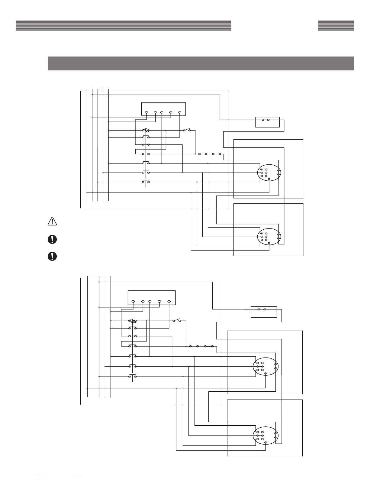
11
LOGOSOL SH410
WIRING DIAGRAM
L3 T3
KONT.
KONT.
KONT.
L2 T2
L1 T1
43
C1
L2 V2 IS P
A1 A2
43
21
BROMSKORT 230V
TILL
FRÅN NÖDSTOPP
5
HUVBR.
TERMOKONT.
GUL/GRÖN
KUTTERMOTOR
6
1
2
3
9
TERMOKONT.
5
MATARMOTOR
GUL/GRÖN
1
2
3
MANÖVERPANEL
L1 L2 L3NJord
ELSCHEMA SOLOHYVEL, 400 V, 3-FAS
L3 T3
KONT.
KONT.
KONT.
L2 T2
L1 T1
43
C1
L2 V2 IS P
A1 A2
43
21
BROMSKORT 230V
TILL
FRÅN NÖDSTOPP
5
HUVBR.
TERMOKONT.
GUL/GRÖN
KUTTERMOTOR
6
1
2
3
TERMOKONT.
5
MATARMOTOR
1
2
3
GUL/GRÖN
MANÖVERPANEL
ELSCHEMA SOLOHYVEL, 230 V, 3-FAS
L1 L2 L3Jord
WARNING! Lethal voltage. Incorrect connection can
result in life threatening injuries.
Note that authorisation is required to open or carry out
work on the electrical equipment.
Make sure that the power has been fully disconnected
before you open the system.
Page 12
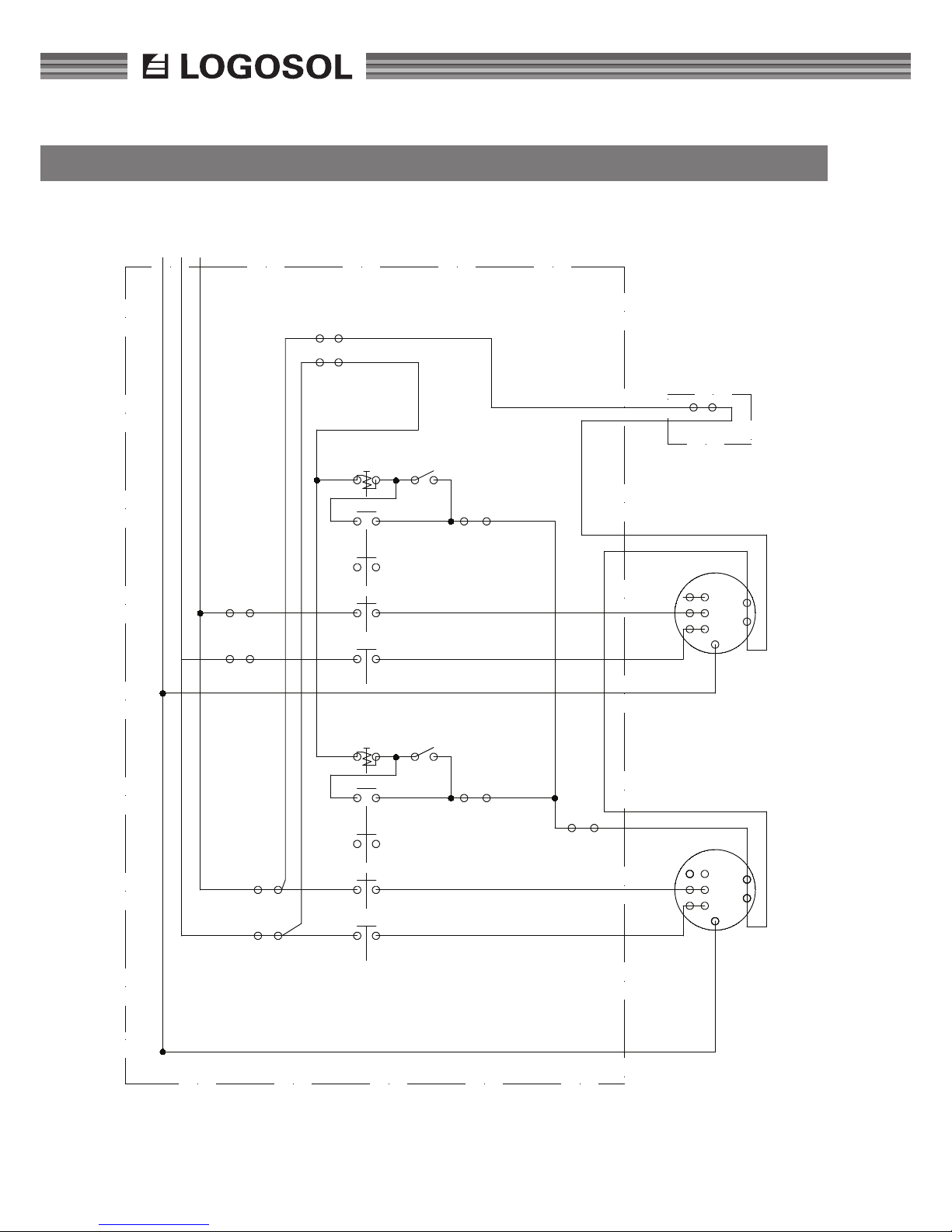
12
WIRING DIAGRAM
L3L3T3
T3
L2L2T2
T2
L1L1T1
T1
A1A1A2
A2
4
4
3
3
4
5
MOTOR 3 kW
1
ELECTRICAL MAIN BOX
ON
ON
Pe, EARTH
HORIZONTAL CUTTER AND SAWBLADE
THERMO SWITCH
CONT.
CONT.
CONT.
CONT.
CONT.
CONT.
YELLOW/GREEN
4
5
MOTOR5MOTOR
THERMO SWITCH
YELLOW/GREEN
OFF
OFF
EMERGENCY STOP
TOP DOOR SWITCH
FEEDING MOTOR
L1N
2
1
2
1
FUSE 16 A (x2)
FUSE 25 A (x2)
FUSE 1 A
FUSE 1 A
ELECTRICAL DRAWING SH410, 230 VOLT 1-PHASE, EU
K1 18
K2 9
Total power 3,2 kW
Connect to 230 V, 1-phase
Fuse 25 Amp
Page 13
13
LOGOSOL SH410
CUTTER WITH PLANING KNIVES, MOULDING KNIVES & SAWBLADE
Make sure that the power is fully disconnected
and that the cutter is not rotating before you
open the cover to service or replace knives.
Use protective gloves, particularly when
loosening screws which are tight or when
tightening screws (refer to 'Safety regulations'). Watch out for the planing knives. It is
very easy to cut yourself on these, even when
lightly touched.
A short wedge is available as an accessory for the
installing moulding knives. The moulding knives'
projection is set by adjusting the planing knives'
removal rate. Short wedges for moulding knives
which are adjustable in the height direction, are also
available.
After replacement of moulding knives, planing
knives or circular sawblade:
Check that no tools have been left in
the machine.
Check that the cutter can rotate freely when
the cover has been closed. This is checked,
when power has been disconnected, by
rotating the pulley on the motor. You reach
the underside of the pulley by extending your
hand under the belt's protective plate.
Panel planer thickness is set using the plane table
crank, (6). The thickness that has been set can be
read on the scale on the machine rack. The scale
can be calibrated. Loosen the stop screw under the
scale and turn to the correct position. Run a board
through and measure using a calliper. Then adjust
tenths and hundredths using the scale on the crank.
Shavings thickness up to 8 mm.
WARNING! Bluntness increases the risk of an
accidents.
Page 14
14
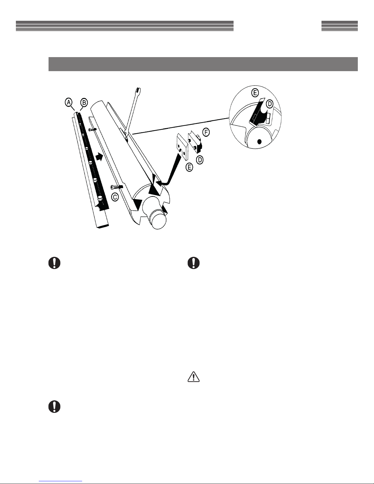
PLANING KNIVES
Refer to the section 'Cutting using planing
knives, moulding knives and circular sawblade'
Planing knives which are in the machine are set, i.e.
set for use on delivery. The knives must however be
regularly ground to ensure that the machine functions well.
DISMANTLING
Loosen the locking screws (B) and press the shavings
breaker down (A). Screw up the planing knife using
the adjustment screws (C).
GRINDING
Always ground the knives in pairs so that they have
the same width, min 15 mm. Vibrations can otherwise arise in the cutter. The grounding angle is to be
40 degrees.
ASSEMBLY
The knives, shavings breaker and cutter are to be
cleaned carefully before knives are tted. Retract
the shavings breaker down into the track. Place the
planing knife straight in relation to the adjustment
screws, so that the adjustment screw heads are in
the recess in the side of the knife and screw the
knife down using the adjustment screws.
The knife's locking screws are in the shavings
breaker.
Undo the locking screws in the shavings breaker, to
allow the knife height to then be adjusted. When
adjustment has been completed, the locking screws
are tightened a little at a time until all are fully tightened.
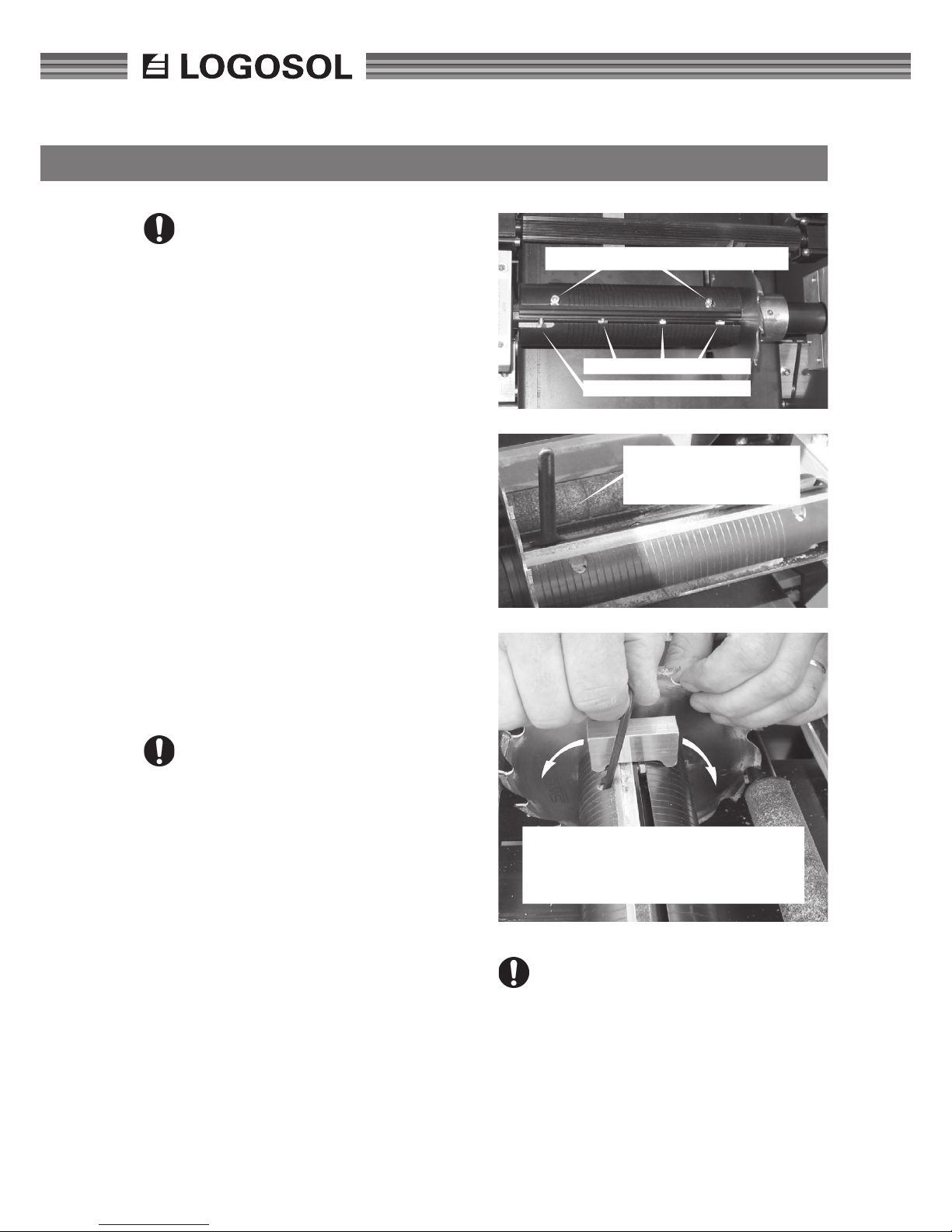
Rough setting of height: Set the height of the
knife using the adjustment screws, so that the rear
edge of the knife is in line with the cutter body.
Fine tuning: Guide the adjustment block (part.no.
7500-000-1020) laterally over the cutter. The knife
should just graze the block when passing over the
knife, when the right height is set. Use this method
to measure on both sides and in the middle of the
knife.
Knife locking screws M6x12
Adjustment screws for height adjustment
Knife locking screws M6x16
Insert a ground 10 mm
spanner to loosen or lock the
knife.
Adjust the height of the knife using the setting block. The knife, when correctly set, just
grazes the block along its entire length, when
the block passes laterally over the cutter.
Tighten the shavings breaker's locking screws
fully when adjustment has been completed.
Finally, screw the adjustment screws carefully
down, until they are tight. The knife will crack
if these are tightened too hard.
Page 15
15
LOGOSOL SH410
MOULDING KNIVES
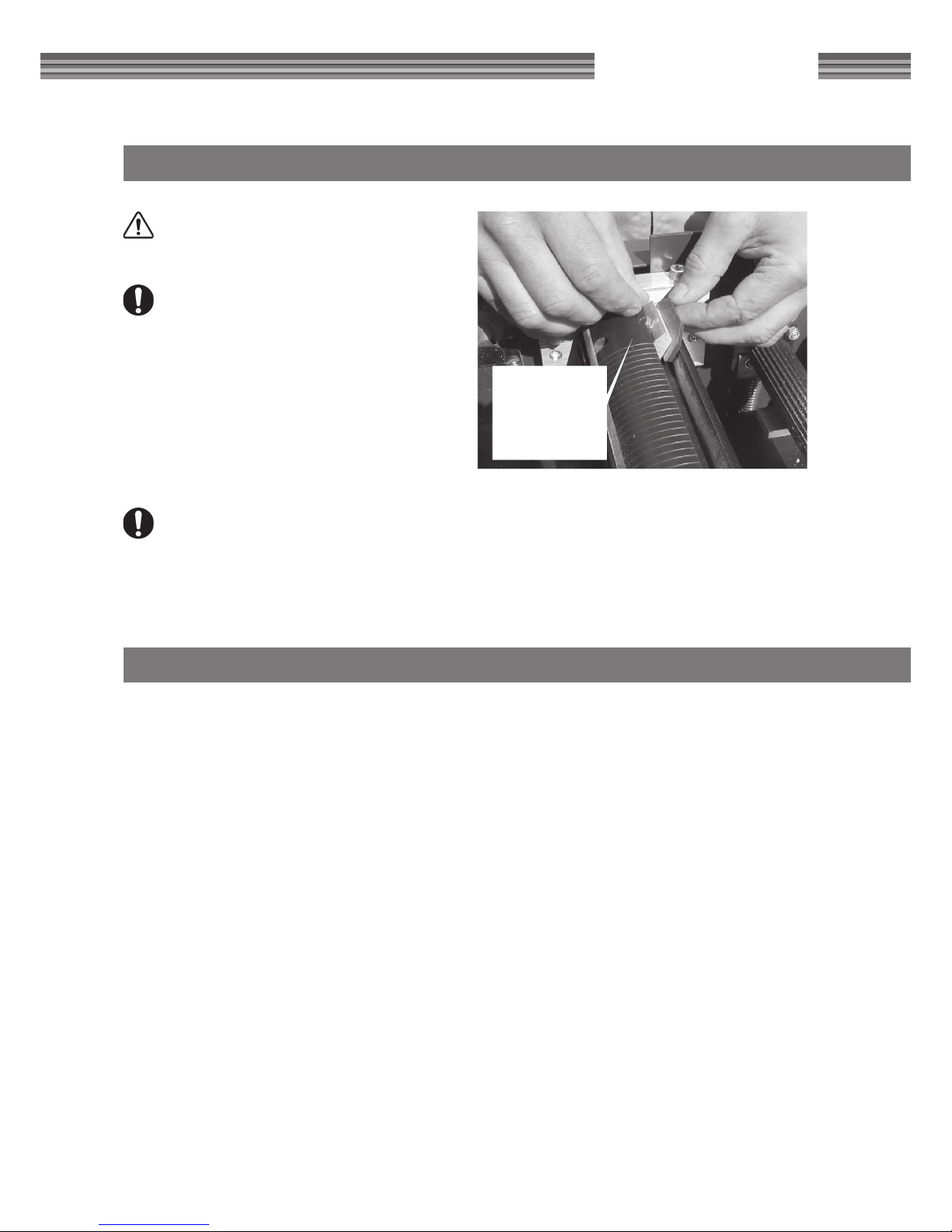
Guide the wedge
with moulding
knife into the
widening in the
cutter's side.
WARNING! Cutter imbalance creates vibrations which can damage the machine and
cause personal injury.
Moulding knives must always be tted in pairs,
so that the cutter remains well balanced.
ASSEMBLY:
• Assemble wedge (D) and moulding knife (E).
• Guide the wedge and moulding knife down the
side of the cutter where the wedge groove is
expanded.
• Push the knife and wedge into the track and attach through screwing out the screw on the rear
of the wedge.
The locking screw is not to be above the
groove of the wedge track.
• Measure the knife's lateral position and t an
identical knife exactly on the cutter's opposite
side.
REPLACING CIRCULAR SAWBLADE
DISMANTLING:
Remove the protective cover for the belt transmission and the rear protective cover for the chain
transmission.
Loosen the belt tensioner and bend the belt off the
spindle pulleys.
Remove the saw spindle through loosening the two
stop screws on each ball bearing inner ring. The
spindle can now be pushed out towards the pulley.
Push out the spindle one decimetre. The four screws
on the blade centre can now be loosened and the
blade can be replaced.
ASSEMBLY:
Clean the bearing and spindle carefully. Fit
the circular sawblade onto the spindle.
Only circular sawblades supplied by Logosol are to
be used.
Fit the protective covers.
Page 16

16
MAINTENANCE
WARNING! Risk of serious damage if maintenance is neglected.
The Solo planer is easy to maintain. Required maintenance is specied below.
Make sure that all power has been disconnected from the machine before you open the
cover or dismantle protective covers.
A good procedure is to ensure that compressed air
is available to blast the machine clean each time
you open the cover. The entire machine should be
cleaned of resin and shavings at the end of each
working day. Take extra care with the feeder rollers'
sprung bearings, the feeder rollers, the out-feed rollers and the cutter. Use alcohol as solvent. Check for
belt stretching (under the protective cover). Check
also that cables, connectors and contacts are in
good condition.
Shavings can be packed under the feeder
roller's and the out-feeder roller's sprung
bearings (4 pcs) which impairs feeding and
increases the risk of rebound.
Check that the teeth of the rebound protection are clean and fall under their own weight.
Make sure that the following components are well
lubricated. Use the appropriate Superow (part.no.
9999-000-5115).
• Feeder roller bearings. Lower the table to the
lowest position.
• The chain which drives the feeder rollers (under
the protective cover).
When you use the machine, regularly clean the table
and treat with low viscosity oil, such as parafn oil.
Regularly check that the motor compartment has
not been lled with shavings. This can otherwise
lead to inadequate motor cooling.
If the machine is not used for a longer period
of time:
• All power is to be disconnected and the machine is to be thoroughly cleaned.
• Repair any damage to paint; wash with alcohol,
scrape off rust and ll the damage with automotive paint. This is to prevent creeping rust
which can increase the damage.
• Then coat the table surface and the components specied above with universal oil (part.no.
9999-000-5105).
• Also coat the moulding knives, planing knives
and circular sawblade with oil. The machine
should ideally be stored in a heated space. If this
is not possible, make sure that the machine is
carefully covered and not in direct contact with
the ground.
Page 17
17
LOGOSOL SH410
FEED
The feeder rollers are driven by a separate motor
and chain transmission.
The feeder rollers must be kept clean of resin and
shavings to ensure they function well. Use Snickarrent (part.no. 7500-001-5000).
The feeder rollers are spring mounted and tted in
the rack. You can experiment by re-setting the feed
pressure using the nuts under the rollers which the
springs are against.
The rollers are to balance directly above the
workpiece.
If a narrow workpiece is processed and the springs
are equally tensioned on the right and left side, then
the the feeder rollers can tilt, which gives poorer
results.
Note the basic setting before you begin to adjust, so
that you can easily return to the original settings if
incorrect. The springs are normally tightened harder
on the circular sawblade side, particularly if narrow
workpieces are to be planed. To check roller pressure: Disconnect the power, lower the table, place
a workpiece under the cutter, raise the table so that
the feeder roller is pressed up. Both sides of the
feeder roller are to then be sprung upwards equally.
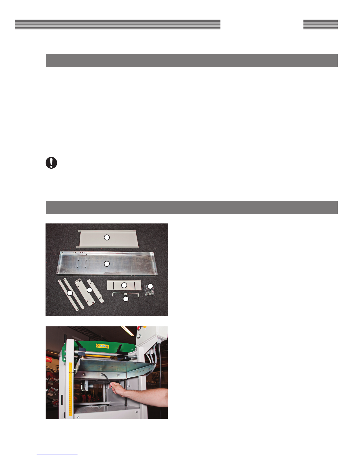
INSTALLING FEED TABLES
1. Remove the original in-feed table. Note that the
bolts will be reused.
Feed table SH410 (accessory)
Included
1. Support plate
2. Feed table
3. Link arms
4. Mounting plates, top mount (only used for
PH260 and DH410)
5. Lower mounting plate
6. Angle adjustment plate
7. Bolt bag
1
2
3
4
5
6
7
Page 18
18
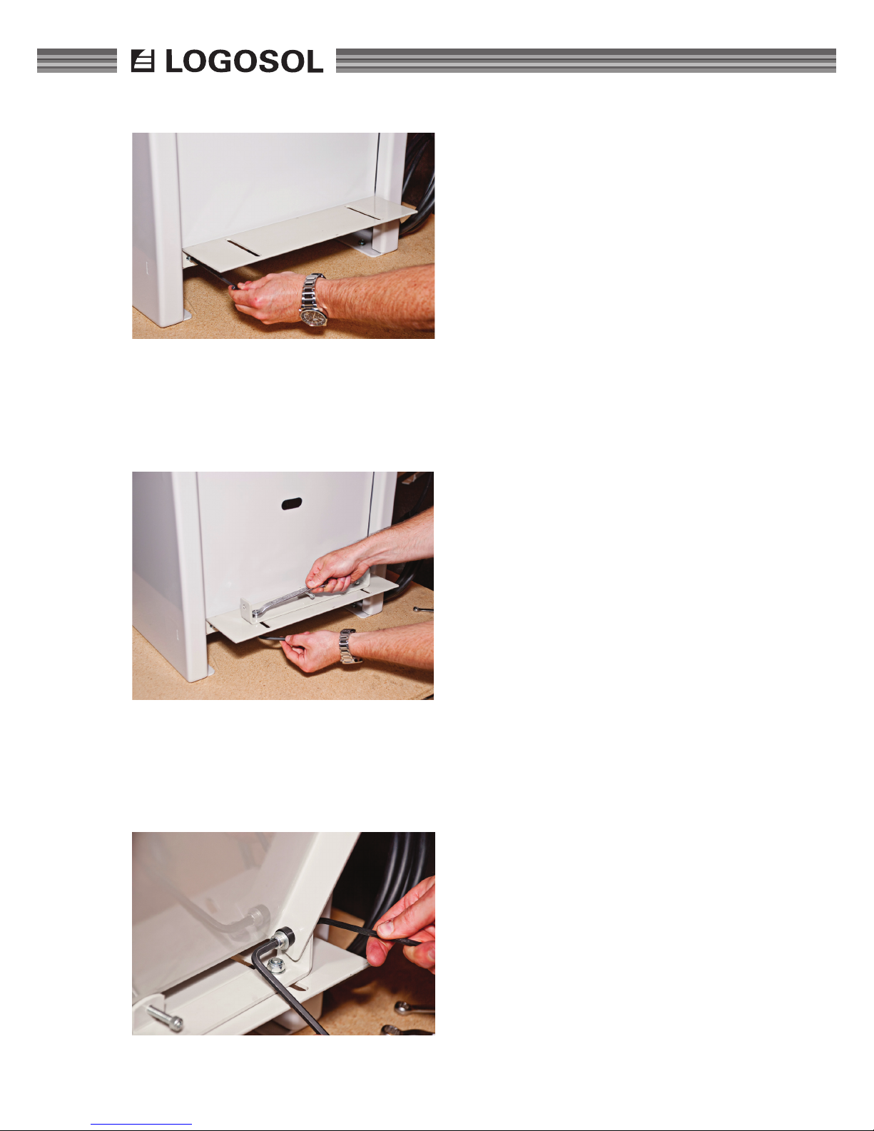
1. Fit the lower mounting plate to the frame using
the original bolts.
2. Fit the angle adjustment plate with two M8x20
incl. washers and locknuts.
3. Attach the support plate with a sleeve nut,
(angle adjustment plate), M10 washer, (support
plate), sleeve spacer, M8 washer and M8x10
bolt.
Page 19
19
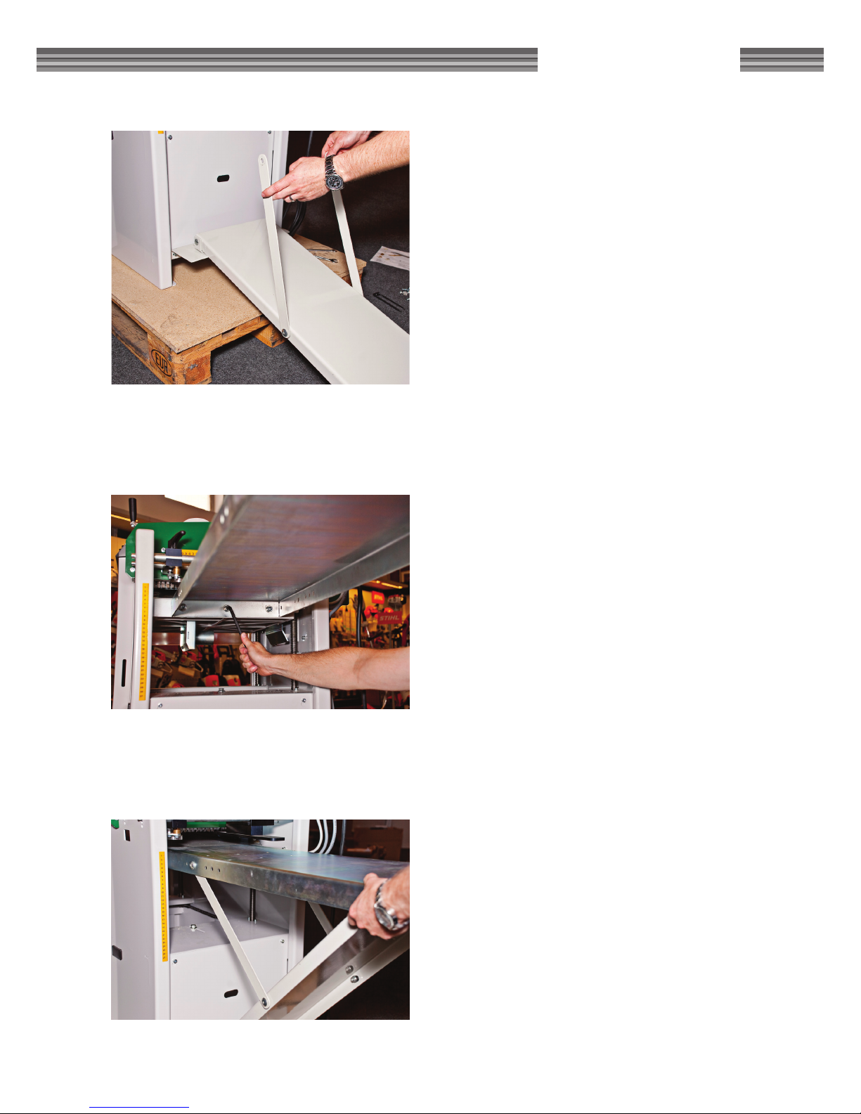
LOGOSOL SH410
1. Fit the link arms outside the support plate usisng
sleeve nuts, (link arm), M10 washer, (support
plate), sleeve spacer, M8 washer and M8x10
bolt.
2. Fit the feed table directly to the cast iron table in
the machine using the original bolts.
3. Fit the link arms to the feed table using sleeve
nuts, (feed table), M10 washer, (link arm) sleeve
spacer, M8 washer and M8x10 bolt.
Page 20
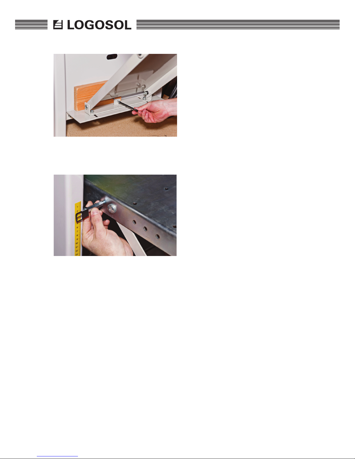
20
1. Adjust the angle of the table. Place something
between the bolt and the machine to avoid
damaging the coating. When the plate is
adjusted to the correct angle you tighten the
M8 bolts and loosen the adjustment bolt a
couple of turns.
9. Install the original pointer for the height scale
using a spacer and two M6x10 hex bolts.
Page 21
21
LOGOSOL SH410
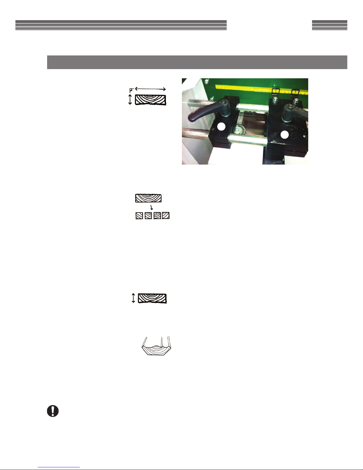
FOUR FUNCTIONS
DIMENSION PLANING:
Set stop (A) to the required
width using the scale on the top
of the planer and lock using the
locking wheel. When dimension
planing, it is the right scale and the left tip on the
double gauge which shows the width of the board.
Adjust the sprung stop (B) so that the working
pressure presses against the stop and lock using the
locking wheel. Set the table to the required board
thickness using the table lever and the scale. Lock
using both locking knobs. Also adjust the height of
the in-feed and out-feed table. Loosen the locking
knob on the machine's sides, adjust using the lever
on the left side. Tighten the locking knob again.
RIP SAWING:
Set the stop (A) to the required
width using the scale and lock using the locking wheel. Adjust the
sprung stop (B) so that the working pressure presses against the stop and lock using
the locking wheel. Set the table to the same height
as the working piece using the table lever and lock
using both locking knobs. If several identical lathe
or moulding workpieces are to be produced, then
the stop and the sprung counterhold should be
switched around. The left scale will then correspond
to the right point on the double gauge.
PLANING:
Loosen the the allen head bolts
in the circular sawblade's locking
sleeve and move it to the countersinks in the shaft
by the side of the table.
MOULDING:
Dimension planing of moulding
workpieces to suitable measurements. Then t the moulding knives
and the locking heals to the cutter. Loosen the top
cover/the shavings duct on the cover and set (alternatively remove completely) the adjustable shavings
breaker. Test run and adjust the moulding knives if
required.
Always check that the cutter can rotate freely
and that no tool or loose screws are left in the
machine.
PLANING TIPS!
• If you have a board which has been very poorly
sawed or if you for any other reason want to remove a lot of wood, set the planer so that it only
takes away as much as it is capable of removing.
Run the board through the planer several times
until you can set the correct dimension.
• Try to avoid timber that is too crooked. It will not
become any straighter because you have planed it.
• Dimension plane a board and measure its exact
width. Then calibrate the double gauge on the
stop, against this. Loosen the screw which holds
the gauge on the side of the table, ne tune
and tighten.
• When you have nished planing a moulding
which you know you will plane again, feed in
a ca 1m long board and shut off the machine
when the end is just in front of the table edge.
Lower the table and take out the board. Next
time the moulding is to be set, the board can be
used as a template for both cutter and stop.
• If the knives in the top cutter are set out too
much, the last feeder roller does not grip. The
projection is to be 1 mm.
• If a lot of wood of the same dimension is to be
planed, a stop can be set on the in-feed table,
so that you quickly can direct in the boards in
the lateral direction before you feed them into
the machine. Logosol has magnetic stops which
attach to the in-feed table. (An alternative can
be to draw a mark on the table, if you have a
crooked work piece.)
B
A
Page 22

22
GOOD TO KNOW
WHICH STEEL QUALITY FOR WHICH
PLANING?
VS, Tool steel also called carbon steel. Hardened
through heating and cooling. TS is used when only
a smaller amount is to be planed. It is cheap but can
begin to loose sharpness already after around 300
running metres. It is the heat which is generated
when planing which makes the knife blunt. TS can
withstand 300 degrees before it is damaged . The
cheap steels which can be found in catalogues and
at ironmongers is TS and can not be compared with
HSS.
HSS, High speed steel or cobalt steel. This is the
steel quality we recommend in most cases. It is
around twice as expensive as TS, but remains sharp
for around 2000 metres, which is a much better
nancial solution in the long term. HSS withstands
700 degrees without being damaged .
HM, Hard metal, also called cormant, is the most
wear resistant steel quality. The hardness of the hard
metal makes the knife as brittle as glass. It is therefore not possible to ground the edge to an angle
that is as sharp as HSS and TS, which means that
it does not cut as well in some materials. HM costs
8-10 times more than TS, but remains sharp for
up to 6000 running metres. HM withstands 1000
degrees without being damaged . Keep in mind that
HM steel must be handled carefully so that it does
not crack. Always place the cutter on a soft surface.
Some special cases: Pine: Use HSS or tool steel.
HM gives a poorer surface. MDF board: Only use
HM. Hardwood: TS cannot be used for planing hardwood. Use ideally also a 4-insert cutter.
THE CUTTER
The Solo planer is supplied with HSS planing knives
in the cutter. These are also available in HM. Above
and below the cutter, holders can also be tted for
replaceable thinner steel, so called Reversible knives
of HSS or HM.
Moulding knives can be tted in the cutter with
the planing knives, which means that the machine
planes and moulds in one operation. There is a large
range of 40 mm moulding knives which can be
combined to achieve the required moulding.
Special steel can be ordered from Logosol. Also
these can be combined to be able to produce more
mouldings using just a few moulding knives.
MOULDING PLANING AND STRAIGHT
PLANING
A moulding planer, such as SH230, is not to be used
to straighten broads. It is to only be used to dimension and mould work pieces. The machine's processing part is to therefore to be built as short as possible, to avoid the straightening effect. Panels and
mouldings are normally not straightened.
A jointer/planer makes the workpiece's sides straight
but does not dimension. A jointer/planer is to have
a long table which steers the work piece straight
over the cutter. The board must then be run through
a planer, dimension planer or moulding planer to
achieve the correct width and height measurements.
Normally only shorter pieces are straightened, for
example for joinery or window production.
These two planer types are not to be confused. They
have separate functions, each being important.
WOOD
Wood shrinks when it dries. The largest shrinkage
takes place when the wood dries from 25% humidity to 10%. To achieve a good surface, you should
not plane wood which has higher humidity than
20% and is as dry as wood can be through outdoor
drying. Ideally the wood is to also be stored indoors
before it is planed.
Wood shrinks very little along the board, along the
bres. You do not, in most cases, need to take this
into consideration . Wood shrinks along annual rings
by around 8% and across annual rings by around
5%. Vertical annual rings are also better in boards.
Boards warp and crack over time. In most cases, the
wood should be turned so that the heartwood side
is the visible surface, to avoid problems with the
wood to the greatest extent possible.
If you are using lock panel, the top boards should be
turned with the heartwood side outwards and the
inner boards with the heartwood side inwards, to
achieve a wall that is as tight as possible.
Page 23
23
LOGOSOL SH410
RESULT
Hard materials provide better surfaces than soft.
Small depressions and light small ames affect the
shavings which accumulate around the edge and
is pressed down into the wood. This phenomena
increases when the steel loses sharpness.
Noticeable cutter impacts in the planed wood are
usually due either to the knives not being adjusted
to the same height or that the workpiece is not
pressed hard enough against the table or stop during processing. A feed speed that is far too high can
also can give visible cutter impact.
Keep feeder rollers clean of shavings. The out-feed
roller is particularly important, as shavings which
stick to this otherwise can make marks on the
planed surface.
Boards that are too warped and crooked, should be
straightened in a jointer/planer or dimension planed
before nal processing is carried out.
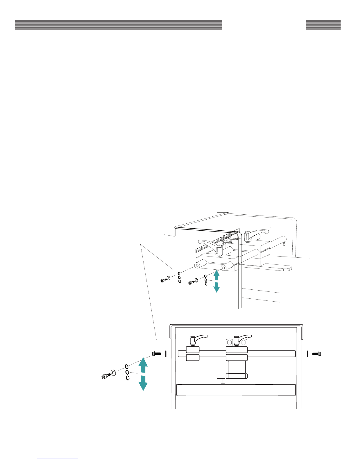
ADJUSTING THE LOWEST
PLANING HEIGHT WITH THE
FENCE
The lowest planing height can be
adjusted by vertically changing
the position of the fence bolts.
You can adjust the height in
three steps, where the rule of
thumb is that the thinner the
piece of wood you are planing
is, the higher the position of
the bolts should be. To adjust
the height, unscrew the Allen
bolts and move the fence to the
desired height.
Page 24
24
SAFETY REGULATIONS FOR MOULDING KNIVES
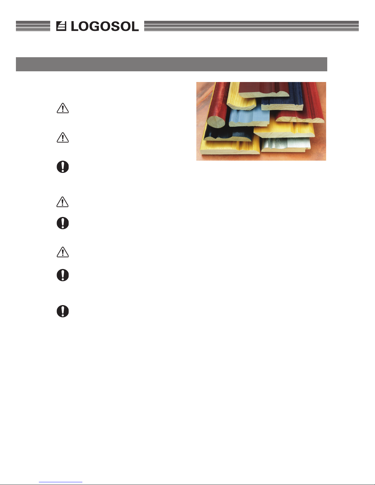
Some of the above mouldings are, when processed,
completely undamaged where the cutter cuts through the
wood piece.
Applies to all moulding knives which have
larger moulding depths than 12 mm
WARNING! When these knives are used, the
risks increase signicantly. Be therefore particularly careful and attentive.
Life threatening! Risk that moulding knives
hit the table during operation. Steel fragments
can be thrown out of the machine.
Check that the cutter can rotate. Moulding
knives easily touch the plastic insert in the
table, but not more than that the cutter can
be turned by hand.
WARNING! Remove the setting crank from
the machine after setting.
Replace the plastic insert in the table if
damage or scores of more than 1 mm are
found.
Life threatening! High risk that planed wood
mouldings are thrown out of the machine.
Respect the safe distances. Set up the
cordoning specied on page 5. Never stand
in front of the in-feed side when in operation.
Make sure that no children are in the vicinity .
Before SH410 is started with these moulding knives: Check that the cutter can rotate
freely and read the machine's safety instructions.
Page 25
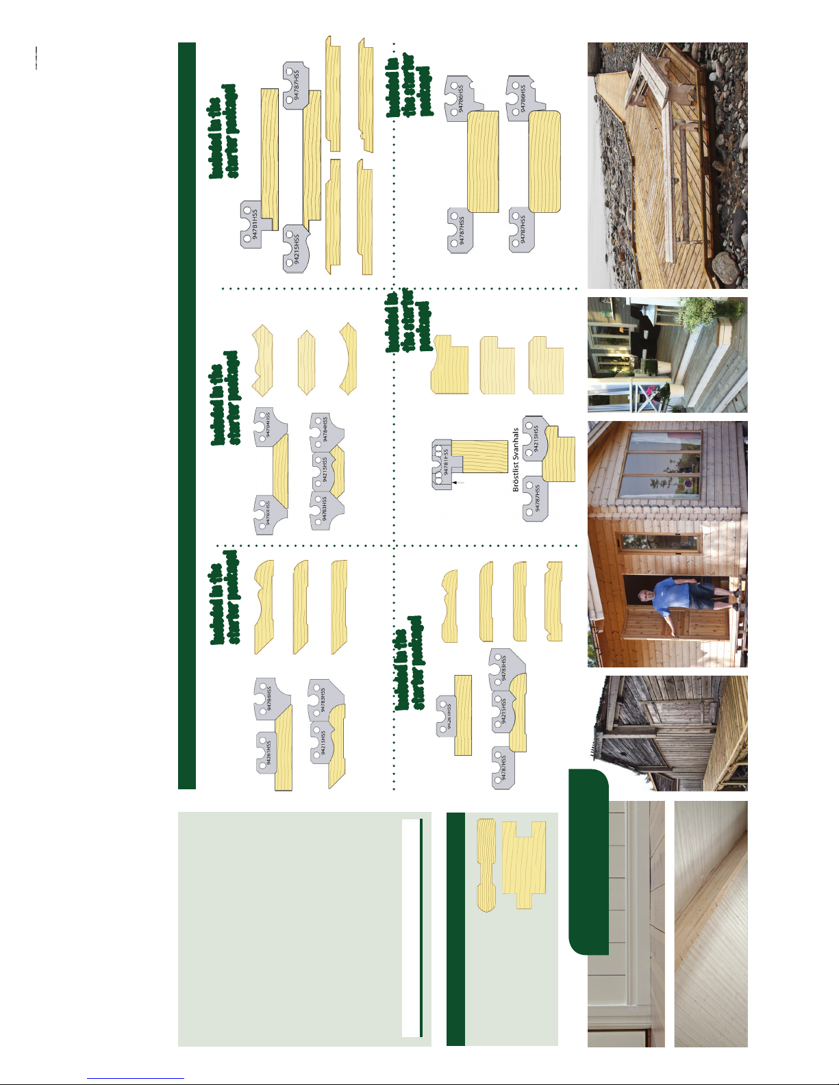
25
LOGOSOL SH410
CORNICES
The package includes: 9 pairs of
moulding knives of HSS, 3 pairs of gibs
and one pair of position holders.
Look at the examples of knife combi-
nations to the right. Let the examples
inspire you, but you can do a lot more with
the starter package!
Starter package with
knives for the SH410
SOLOHYVEL SH410 Knives
Carefully selected knives – plane and mould for your project!
Starter package with knives and
gibs for the SH410
5.390:-
TB90-010
The wood proles
on this page are just
examples of what you
can do with the knife
package.
Handrails, T&G and much more
Included in the
starter package!
Included in the
starter package!
Example of wood proles you can make with the knives in the starter package
Brush-painted wooden details
add a genuine and homely touch!
Plain skirting board
WAINSCOT MOULDINGS
Rounded
SKIRTING BOARDS
Rustic style cornice
Rustic style skirting board
Plain skirting board 1
Plain skirting board 2
Bevelled
Rustic style
Cove crown
PANELLING
Open bevelled T&G Close rounded T&G
Beaded T&G
Open rounded T&G
One knife
is displaced a
couple of mm
from its lateral
position in rela-
tion to the
other knife.
CASINGS
Plain casing 1
Plain casing 2
Rustic style casing
Beaded casing
Close bevelled T&G
Included in the
starter package!
Included in the
starter package!
Included in
the starter
package!
Included in
the starter
package!
Joists, 5 mm radius.
JOISTS & DECKING
Page 26
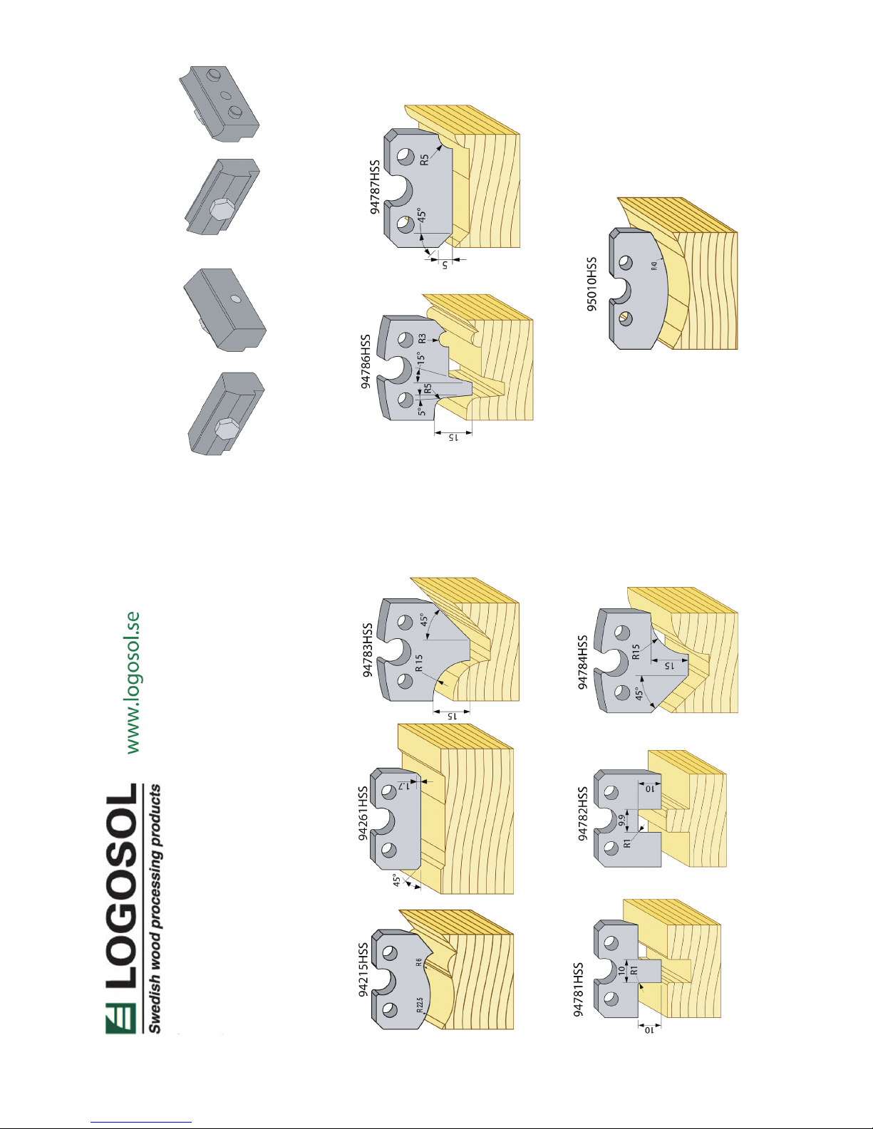
26
BASIC PACKAGE SH410 ITEM NO: TB90-010
6 pairs of moulding knives of HSS + 3 pairs of knife gibs
+ 1 pair of position holders for making:
Casing
Rounded panelling
Bevelled panelling
Wainscot moulding
Cornice
Skirting board
Joists & Decking
POSITION HOLDERS X1 KNIFE GIBS -038 X3
Page 27
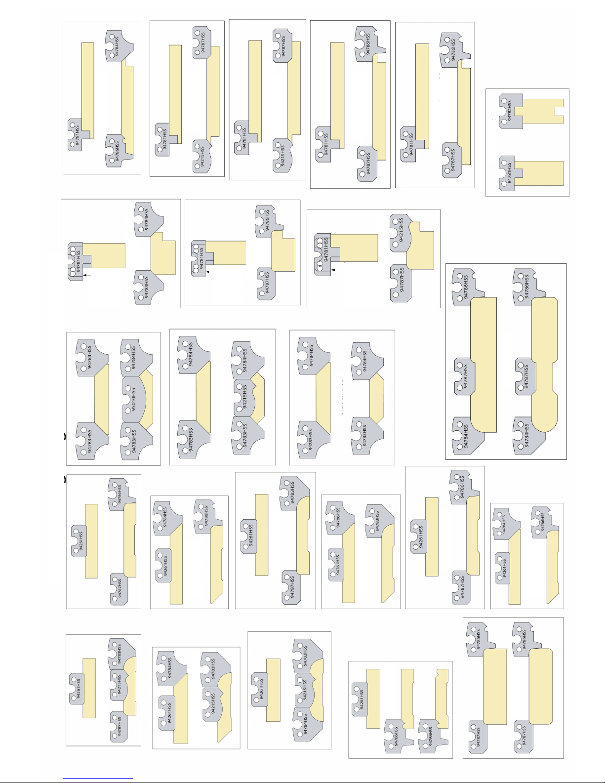
27
LOGOSOL SH410
Knife mounting in the LOGOSOL SH410
Rustic style casing
Rustic style skirting board
Rustic style casing 2
Beaded casing
Joist & decking
Rounded casing 1
Rounded skirting
board 1
Rounded casing 2
Rounded skirting
board 2
Rounded casing 3
Rounded skirting
board 3
Cove crown
Swan neck cornice
Plain cornice
Wainscot moulding,
bevelled
Wainscot moulding,
rounded
Wainscot moulding, swan neck
Hand rail
Beaded panelling
Double bevelled
panelling
Double bevelled
panelling (open)
Double rounded
panelling
Double bevelled
panelling (open)
T&G
One knife is
displaced a couple
of mm from its
lateral position
in relation to the
other knife.
One knife is
displaced a couple
of mm from its
lateral position
in relation to the
other knife.
One knife is displaced
a couple of mm from
its lateral position in
relation to the other
knife.
Page 28
28
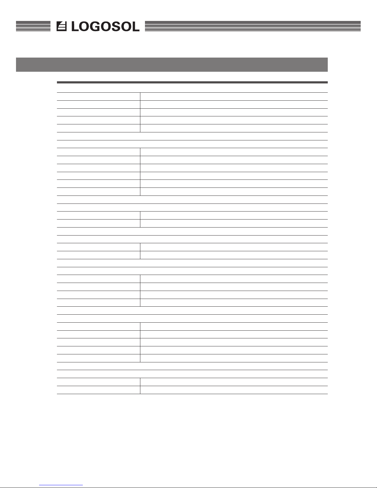
TECHNICAL DATA SH410
PROCESSING MEASUREMENT
Max material width 410 mm
Max panel planer width 410 mm
Max panel planer height 260 mm
Min planer height 6 mm
Max splitting 80 mm
CUTTING EQUIPMENT
Cutter diameter 72 mm
Planing knives 2 x 410mm HSS
Shavings thickness 4 mm
Circular sawblade ø 225 mm
Rotational speed 5400 rpm
Stop time for cutter ca: 7 sec
SHAVINGS HANDLING
Shavings duct diameter 125+100+50 mm
Required chip extractor capacity 1500 m2/h
POWER SUPPLY
Feed rate ca: 6 m/min
Number of rollers 3
DIMENSIONS
Length 1100 mm
Width 700 mm
Height 1050 mm
Weight ca. 200 kg
ELECTRICAL SYSTEM
Power supply CCA16 A, 400 V 50 Hz three phase, or 25 A 230 V 50 Hz three phase
Protection rating IP54
Rated power, main motor 3kW
Rated power, feed motor 0.18 kW
Main breaker The contact for power supply is disconnected.
NOISE LEVELS
Sound pressure level 100.4 dB(A)
Noise effect value 107.6 dB(A)
Page 29

29
LOGOSOL SH410
Page 30

30
Page 31

31
LOGOSOL SH410
Declaration of conformity
Manufacturer
MORETENS AB,
Nifsåsvägen 11
S-831 52
Östersund, Sweden
Tel. +46 63 121890,
hereby conrms that SH 410,
with part. no. 245-000
has been manufactured in conformity with:
Machinery Directive 98/37/EC, EMC Directive
2004/108/EC
and LVD directive 2006/95/EC,
and in accordance with
the following harmonized standards:
EN ISO 12100-1, -2:2003, EN 60204-1:2006,
EN 61000-6-1, -3.
Östersund, Sweden, 1 November 2011
MD Bo Mårtensson
Page 32

LOGOSOL SWEDEN
Fiskaregatan 2, SE-871 33 Härnösand, Sweden
Tel. +46 (0) 611-182 85 | Fax +46 (0) 611-182 89
[email protected] | www.logosol.se
 Loading...