

Page 1
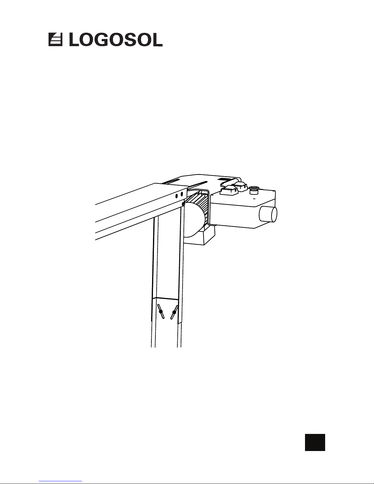
USER MANUAL
Ref. no. 0458-395-0552
OPTIONAL ATTACHMENT
ELECTRIC FEED UNIT
EN
Page 2
LOGOSOL continuously develops its products.
For this reason, we must reserve the right to modify
the conguration and design of our products.
Document: Electric Feed Unit
Ref. No. User Manual, English: 0458-395-0552
Text: Mattias Byström, Robert Berglund
Illustrations: Mattias Byström, Martin Söderberg, Robert Berglund
Last revised: Augusti 2018
© 2018 LOGOSOL, Härnösand Sweden
THANK YOU FOR CHOOSING A LOGOSOL PRODUCT!
Read through the user manual
carefully and make sure you
understand its contents before you
use the equipment.
This user manual contains important
safety instructions.
WARNING! Incorrect use can result
in serious or fatal injuries to the
operator or others.
Welcome! We are very pleased that you have demonstrated your condence in us by
purchasing a LOGOSOL product, and we will do our utmost to meet your expectations.
LOGOSOL has been manufacturing sawmills since 1989. In that time we have supplied
approximately 50,000 machines to satised customers the world over.
We care about your safety as well as we want you to achieve the best possible results with
your equipment. We therefore recommend that you take the time to carefully read this
user manual from cover to cover in peace and quiet before you begin using the equipment.
Remember that the equipment itself is just part of the value of the product. Much of the value
is also to be found in the expertise we pass on to you in the user manuals. It would be a pity if
that were not utilised.
We hope you get a lot of satisfaction from the use of your new LOGOSOL product.
Bengt-Olov Byström
Founder and chairman,
Logosol in Härnösand, Sweden
#1
Page 3

Safety instructions 4
Description of the equipment 5
Components: on delivery 6
Components: electric feed unit 7
Components: support leg 8
Components: wire tensioner 9
Tools required 10
Assembly: support legs 12
Assembly: wire tensioner 14
Assembly: electric feed unit 16
Assembly: wire and wire attachment 18
Adjustment: support legs 22
Adjustment: wire tensioner 23
Adjustment: electric feed unit 24
Control panel 26
Control lever 27
Operation: forward feed 28
Operation: reverse feed 29
Maintenance 30
Troubleshooting 32
Wiring diagram 33
Exploded views 34
CE Declaration of conformity 39
TABLE OF CONTENTS
Page 4
4
• Read carefully through the entire user manual
before starting to use the product. Failure to
observe these safety instructions may result in
fatal injuries.
• Make sure that everyone who uses the product
is well informed of the dangers and has read
the user manual. The user manual shall always
be available to the persons working with the
product. This also applies where the product is
sold or loaned out.
• Minors under 18 years of age are not allowed to
use the product.
• Make sure that children and animals are not in
the vicinity when the product is being used.
• Anyone working with the product must be
t for work, healthy and in good physical
condition. Make sure you take regular breaks
when working with the product. Never use the
product while under the inuence of alcohol,
narcotics or other drugs or medicines that can
cause drowsiness or inattention.
• The product is only to be used where visibility is
good. It is not to be used in the dark or where
visibility is poor.
• Make sure there are other persons within
earshot who you can summon if you need help.
• VOnly add extra equipment to the product
that is made by LOGOSOL or that is specically
approved by LOGOSOL for the purpose. Other
equipment can cause accidents and should not
be used. LOGOSOL will not accept liability for
personal injury or material damage that occurs
while using non-approved attachments on the
product.
• If the saw unit used weighs more than 15 kg,
support legs must be tted under the guide rail
ends. Risk of overturning.
• Always wear protective clothing and use
personal protective equipment: Close-tting
work overalls are appropriate. Never work with
the product wearing loose-tting clothes, overall
coats or similar.
• Use safety shoes with high-grip soles and steel
toecaps. Neckerchiefs, ties, jewellery or other
items that can get caught in the equipment are
not to be worn.
• Wear strong protective gloves.
SAFETY INSTRUCTIONS
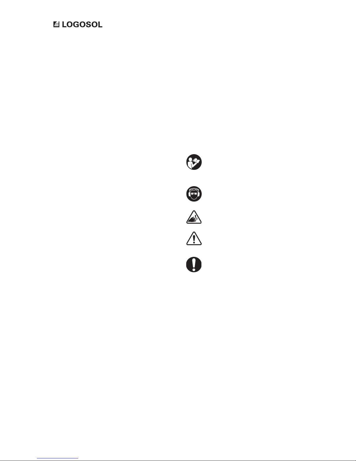
Key to symbols
For your own safety, read through the
entire user manual carefully and do not use
the product before you have understood
everything.
Use approved ear protectors and protective
eyewear. Hearing can be damaged even
after short periods of exposure.
Sharp rotating tools. Make sure that your
ngers never come near the cutting tools.
This symbol means ’WARNING’. Pay
particular attention where this symbol
appears in the manual text.
This symbol is followed by instructions that
must be observed. Pay particular attention
where this symbol appears in the manual
text.
Page 5

5
OPTIONAL ATTACHMENT ELECTRIC FEED UNIT
DESCRIPTION OF THE EQUIPMENT
The product has several integrated functions.
- Forward and reverse feed with stepless, variable
pressure.
- Control panel for electric saw unit or log moulder
- Loading ramp that makes it easy to push the saw
unit onto the guide rail.
En stor fördel med friktionskopplingen är att du
indirekt reglerar hastigheten på aggregatet genom
att ställa drivningstrycket. Detta gör att farten delvis
blir självjusterade. A great advantage of the friction
clutch is that you indirectly regulate the speed of
the saw unit by adjusting the feeding pressure.
This makes the speed partly selfadjusting. The saw
unit will accelerate or decelerate depending on the
dimension and quality of the log. This makes the
feed unit very easy to operate. Also, there will be
less stress on the cutting equipment, since the speed
is immediately adjusted when sawing through a
knot or swelling in the log.
This can be compared to feeding machines that have
adjustable speed, where the cutting equipment is
exposed to very high stress when the cutting unit
meets with temporary resistance that the operator
does not manage to compensate for.
With the LOGOSOL Electric Feed Unit the guide
bar and the chains will last longer, and it is easy to
maintain optimum sawing speed.
Page 6
6
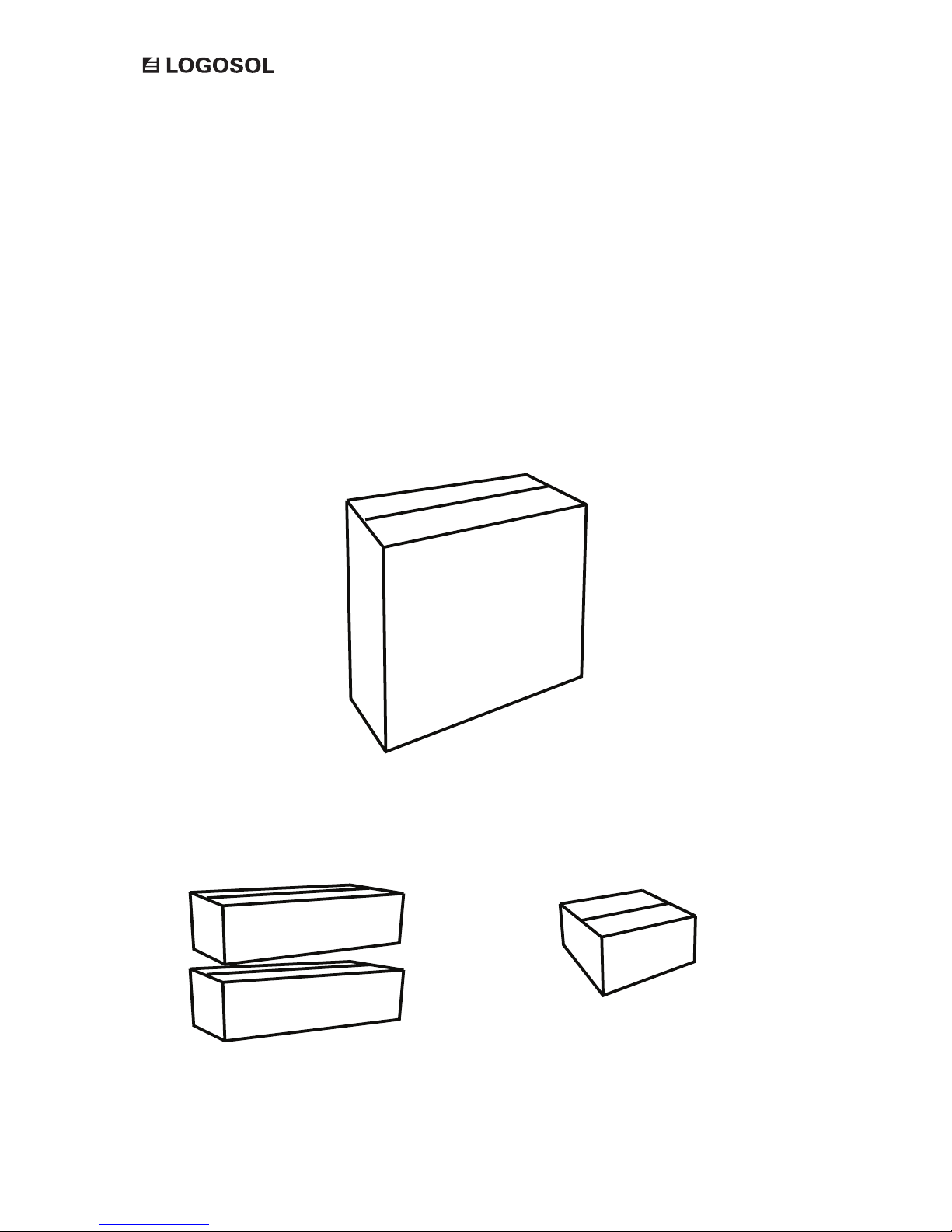
The product comes in 4 boxes consisting of 1 wire tensioner, 2 support legs, and 1 electric feed unit. Check
that all of these boxes are included in the shipment when receiving it.
Support legs
6600-000-3005
Electric feed unit
6600-000-3035 (400V)
6600-000-3040 (230V)
Wire tensioner
01-00339
COMPONENTS: ON DELILVERY
Page 7
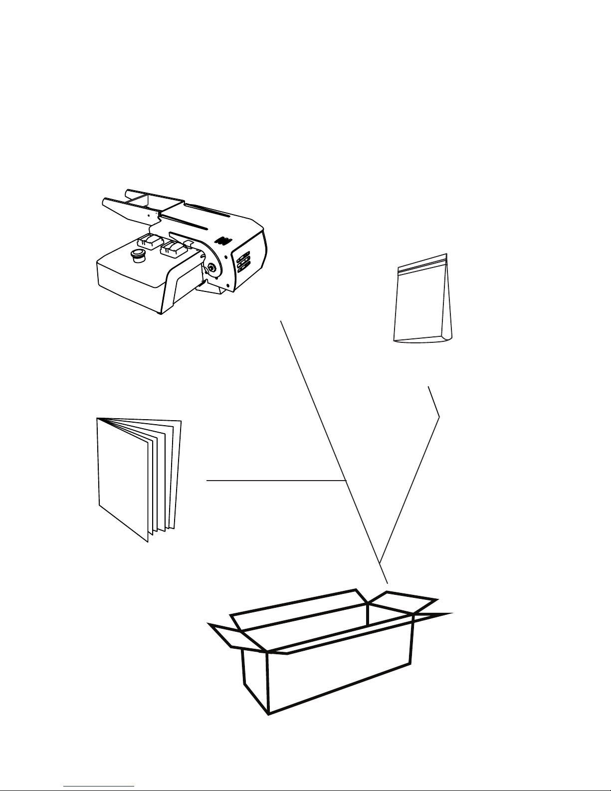
7
OPTIONAL ATTACHMENT ELECTRIC FEED UNIT
Bolt bag
Electric feed unit
Electric feed unit
6600-000-3035 (400V)
6600-000-3040 (230V)
Contents of the box.
COMPONENTS: ELECTRIC FEED UNIT
User manual
Page 8
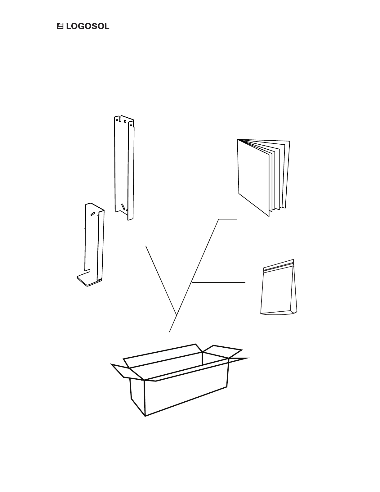
8
Bolt bag
Contents of the box.
Support leg
6600-000-3005
Assembly instructions
on page 12
Support leg, top
Support leg, bottom
COMPONENTS: SUPPORT LEG
Page 9
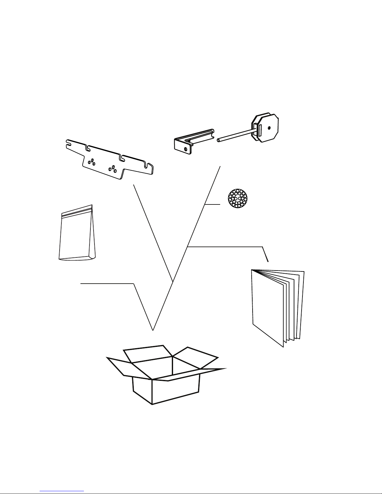
9
OPTIONAL ATTACHMENT ELECTRIC FEED UNIT
Contents of the box.
Wire tensioner
01-00339
COMPONENTS: WIRE TENSIONER
Bolt bag
Bracket and wheel housing
Assembly instructions
on page 14
Wire attachment
Wire
Page 10
10
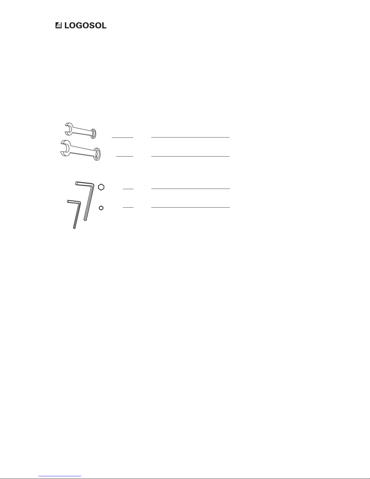
These tools are not included in the shipment.
1 x
1 x
Fixed spanner 10 mm
Fixed spanner 13 mm
TOOLS REQUIRED
1 x
1 x
Allen key 6 mm
Allen key 5 mm
Page 11
11
OPTIONAL ATTACHMENT ELECTRIC FEED UNIT
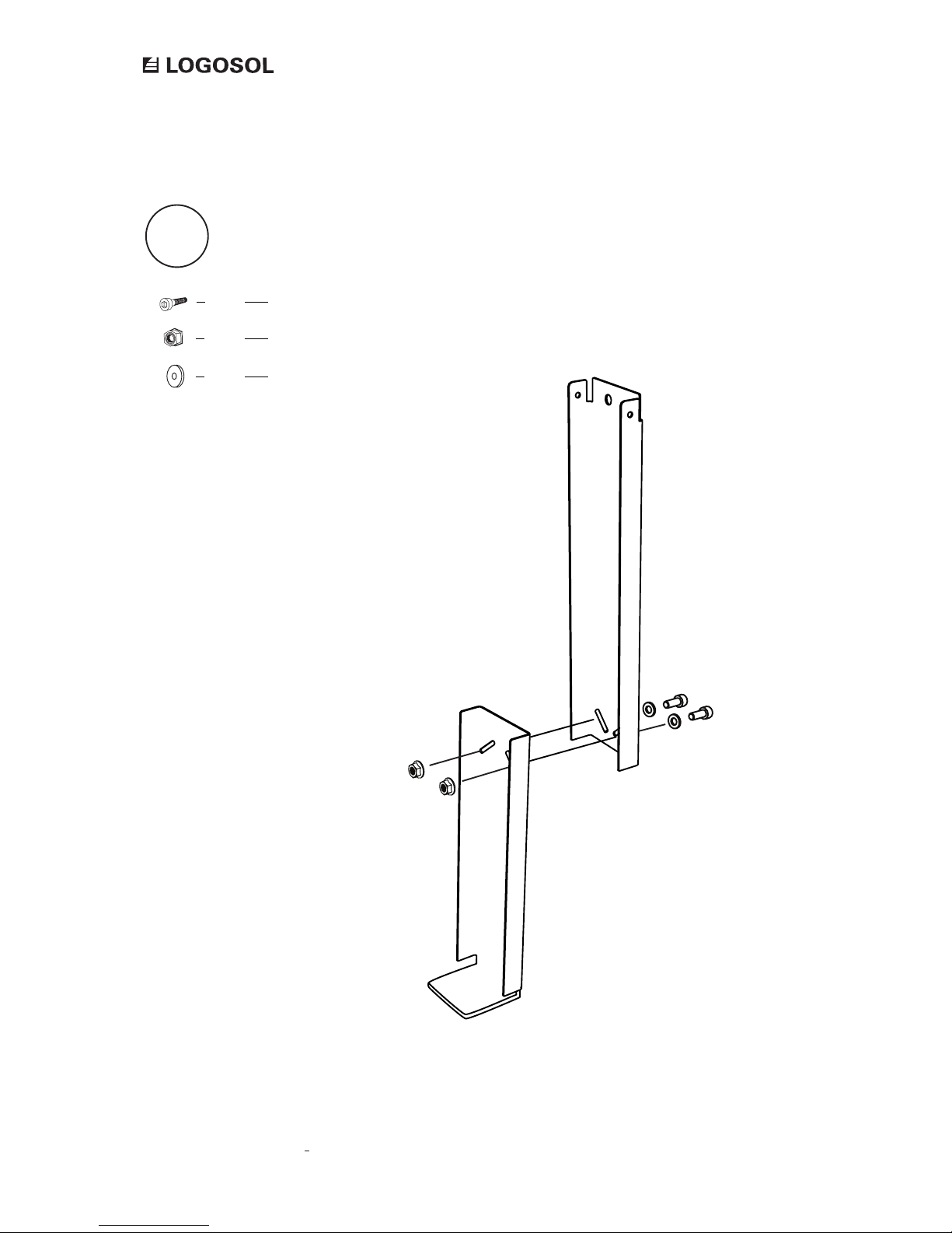
We recommend that you start with assembling the support legs. These are identical, and
all components needed are found in the leg support boxes.
We recommend that you place all fastening elements on a tray or the like
to facilitate nding the bolts, nuts, etc.
Open one of the leg support boxes and start assembling.
Support leg
6600-000-3005
Here we go!
Page 12
12
Allen bolt M8x20
Flange lock nut M8
Washer M8
2 x
2 x
2 x
1
ASSEMBLY: SUPPORT LEG
Page 13
13
OPTIONAL ATTACHMENT ELECTRIC FEED UNIT
To continue with the next step you need the
components from the wire tensioner box.
Open the wire tensioner box.
Wire tensioner
01-00339
Good job!
Page 14
14
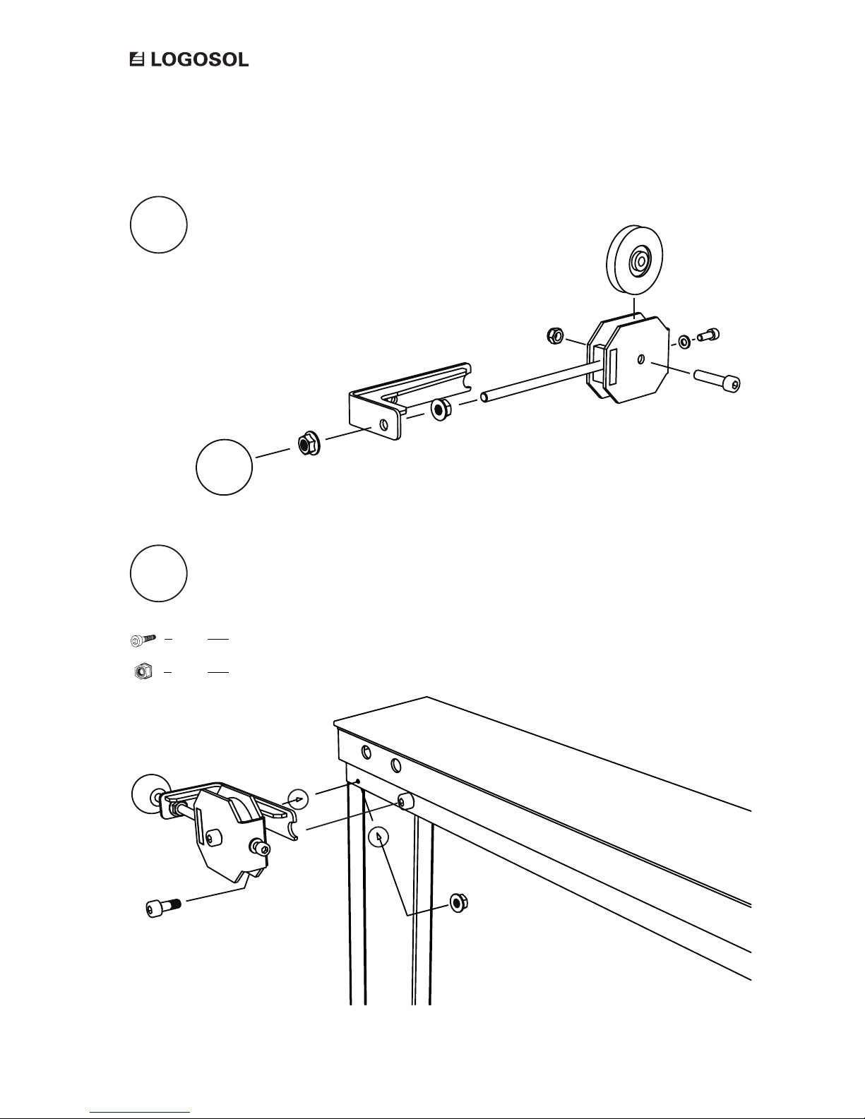
1
2
ASSEMBLY: WIRE TENSIONER
Assemble the wire tensioner.
Fit the wire tensioner and the support leg to the guide rail.
Allen bolt M6x20
Flange lock nut M6
1 x
1 x
Page 15
15
OPTIONAL ATTACHMENT ELECTRIC FEED UNIT
To continue with the next step you need the
components from the electric feed unit box.
Open the electric feed unit boxt.
Electric feed unit
6600-000-3035 (400V)
6600-000-3040 (230V)
Good job!
Page 16
16
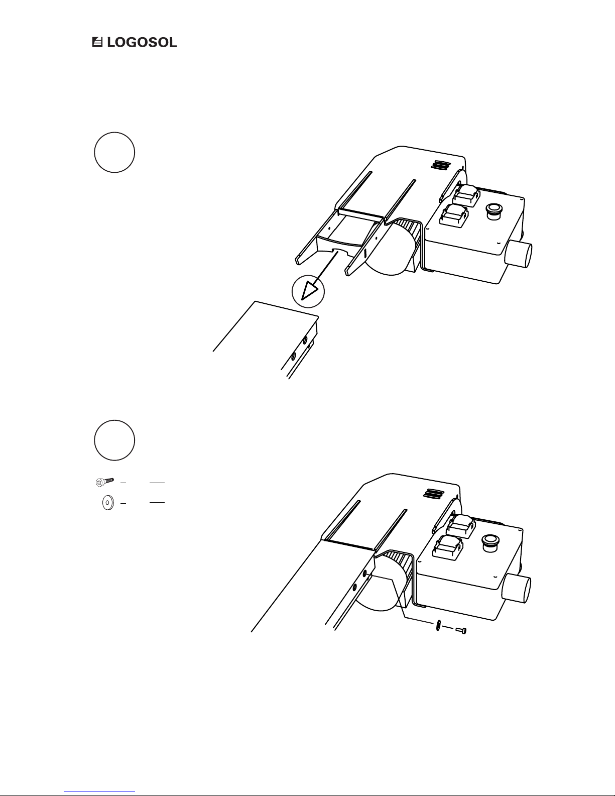
Slide the feed unit forks into the guide rail end.
Secure the feed unit with bolts in the guide rail.
1
2
Allen bolt M6x20
Washer 20 mm
1 x
1 x
ASSEMBLY: ELECTRIC FEED UNIT
Page 17
17
OPTIONAL ATTACHMENT ELECTRIC FEED UNIT
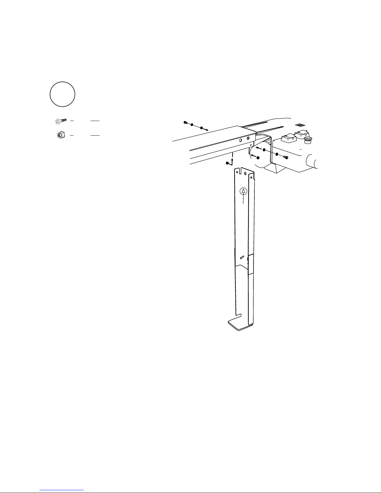
Fit the support leg to the guide rail.
Allen bolt M6x20
Flange lock nut M6
2 x
2 x
3
ASSEMBLY: ELECTRIC FEED UNIT
Page 18
18
Now it is time to assemble the wire and the wire attachment.
The components needed are in the wire tensioner box.
Wire tensioner
01-000339
Good job!
Page 19
19
OPTIONAL ATTACHMENT ELECTRIC FEED UNIT
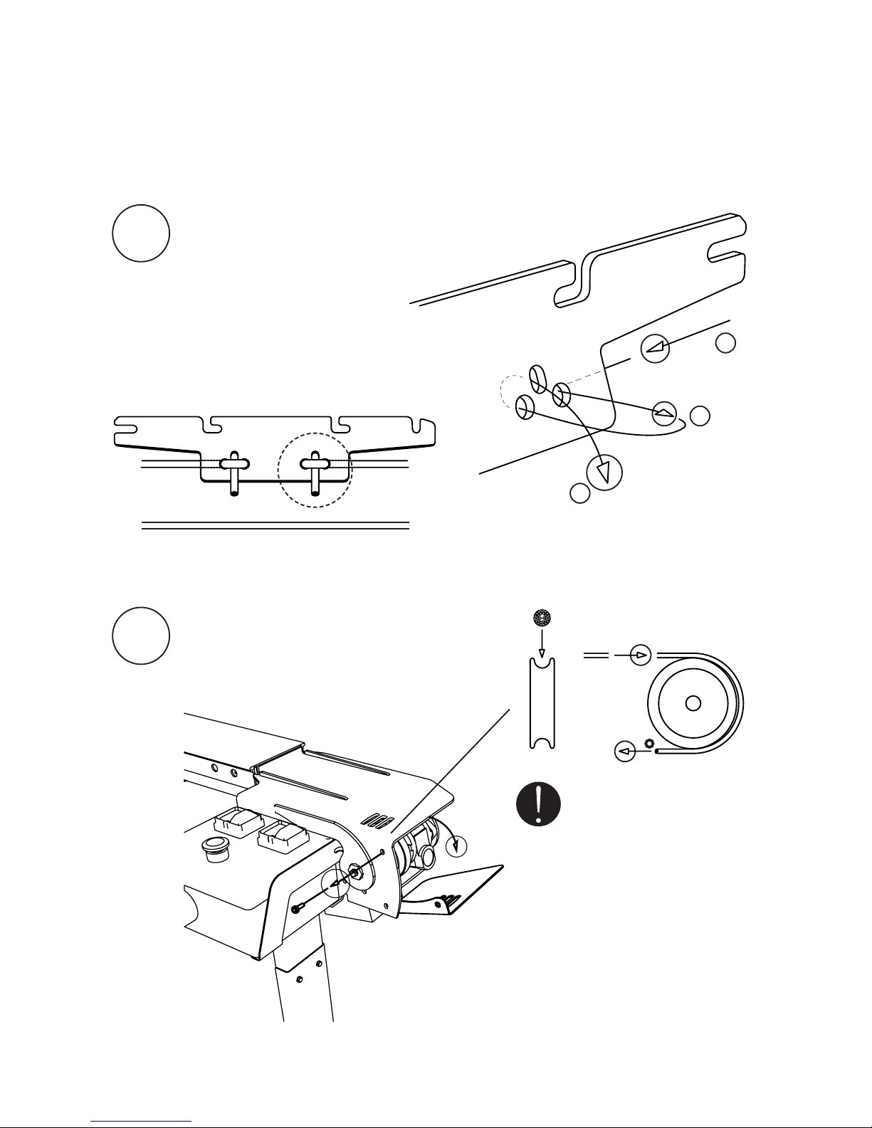
ASSEMBLY: WIRE AND WIRE ATTACHMENT
1
Fasten one of the wire ends to the wire attachment.
2
Pass the wire around the pulley.
Open the hatch for better access.
1
2
3
Important: Make sure that
the wire is led below the guide
bolt, which is located after the
pulley.
Page 20
20
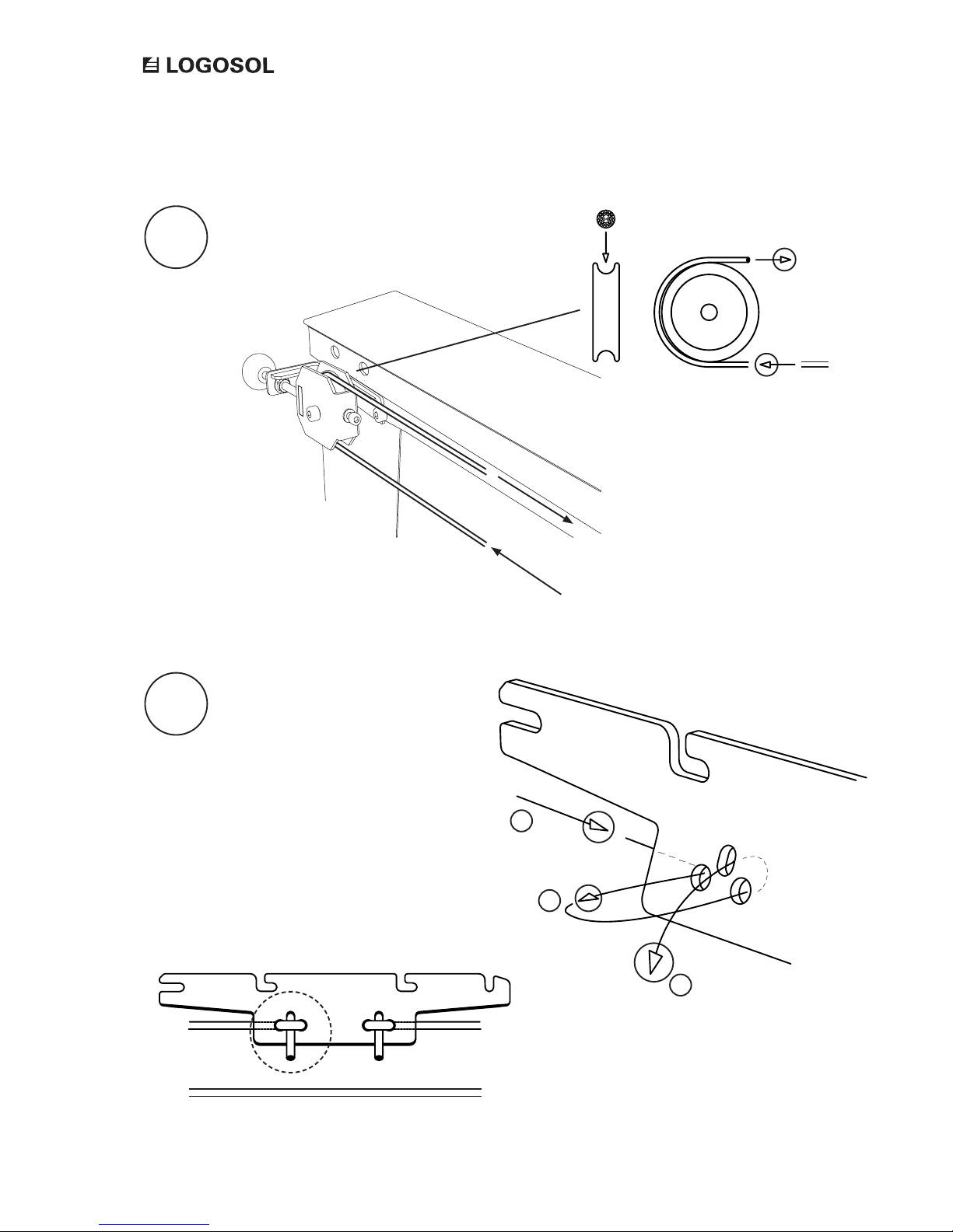
3
ASSEMBLY: WIRE AND WIRE ATTACHMENT
Pass the wire through the wire tensioner
and around the pulley.
4
Fasten the wire end to the wire
attachment.
1
2
3
Tip: Tighten the wire as much as
posible by hand before fastening
it to the wire attachment.
Page 21
21
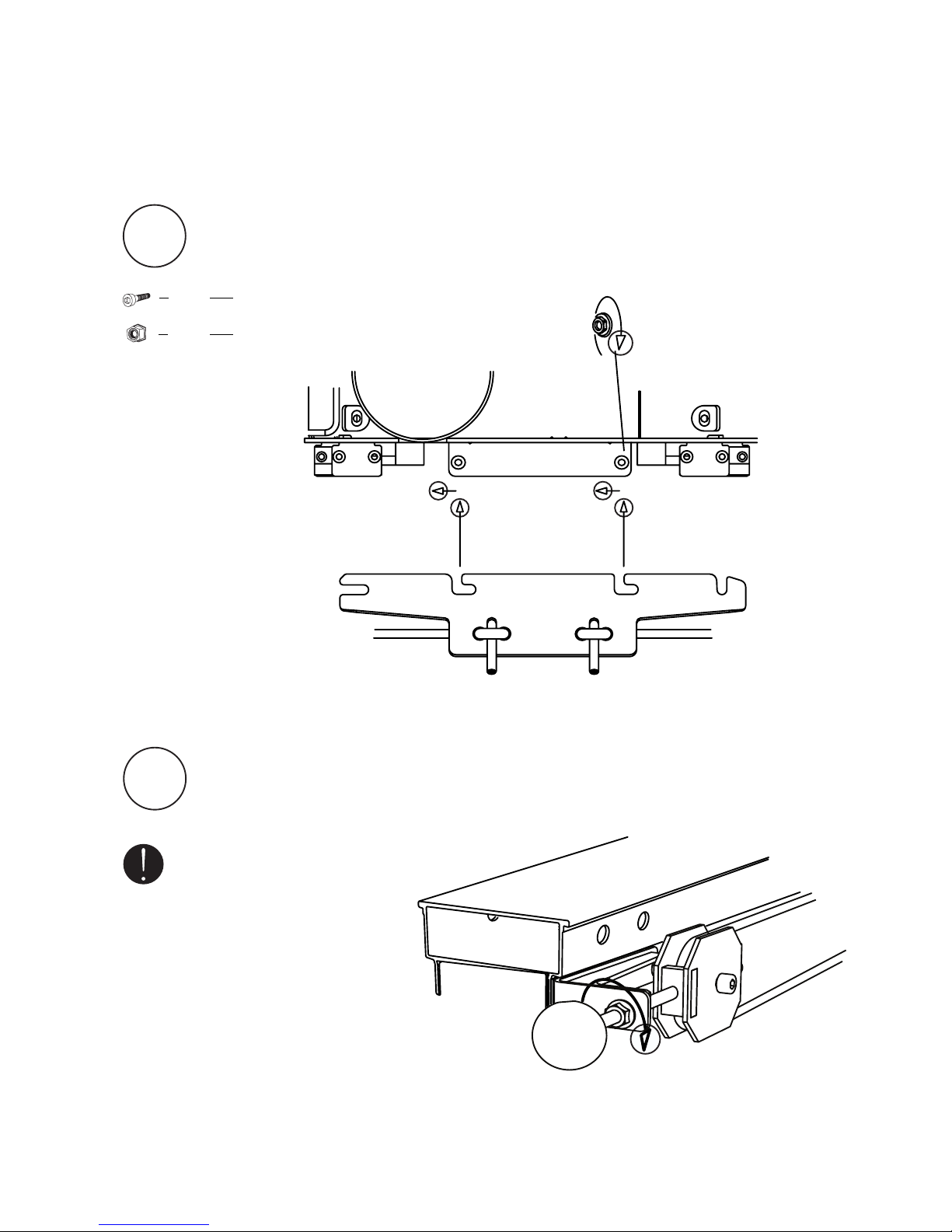
OPTIONAL ATTACHMENT ELECTRIC FEED UNIT
5
Screw the bolts to the fastening plate on the saw unit. Secure the wire attachment
with the nuts.
ASSEMBLY: WIRE AND WIRE ATTACHMENT
6
Tighten the wire with the wire tensioner.
Important: It is important that
the feed unit has the right wire
tension to work satisfactorily.
Tighten the wire until it stops
slipping in the pulley. The wire
tension may need to be readjusted
after a period of use.
Allen bolt M6x20
Flange lock nut M6
2 x
2 x
Page 22
22
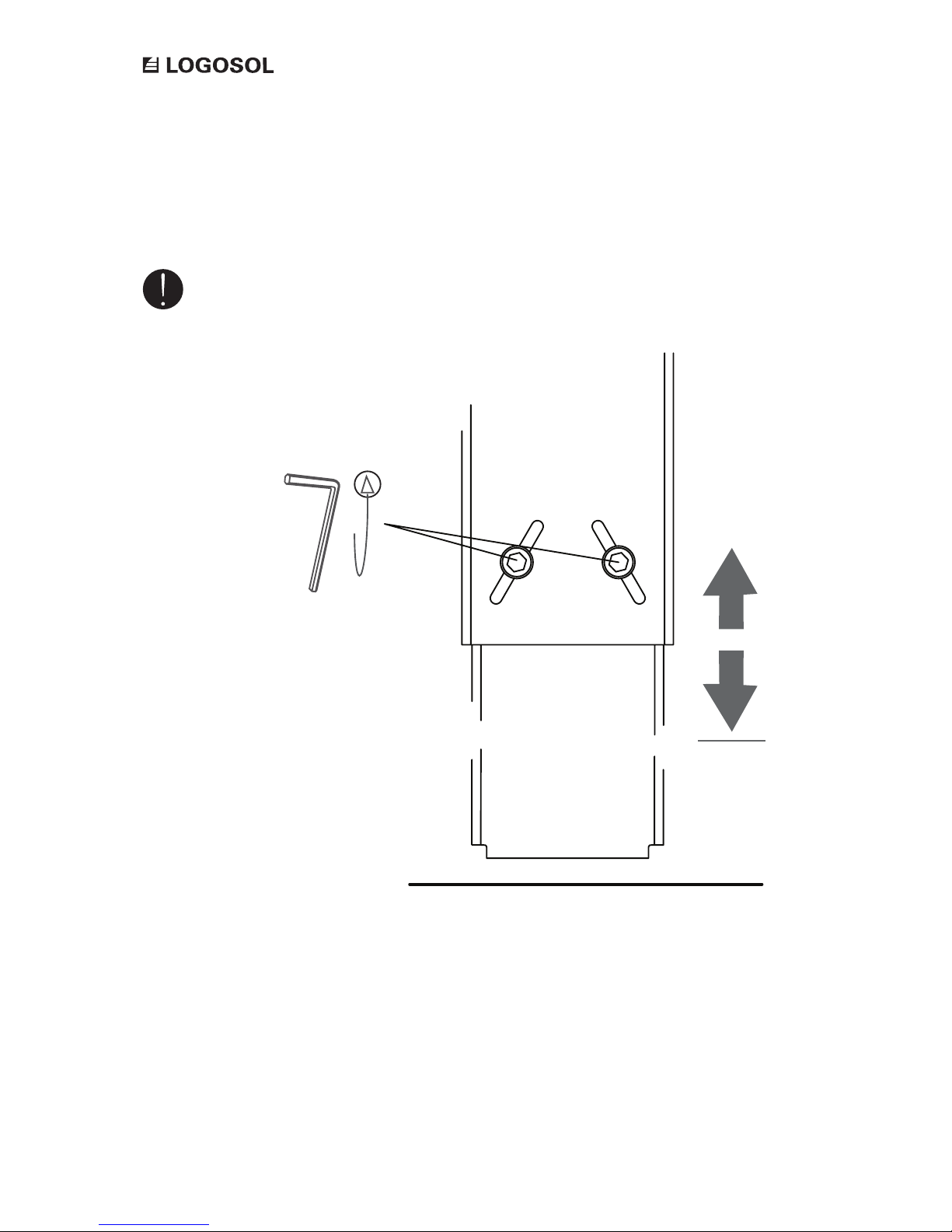
ADJUSTMENT: SUPPORT LEGS
The support legs can be adjusted vertically by loosening the two adjusting bolts. Adjust the height
of the support leg until it rests lightly against the ground.
Important: The supports legs
should just rest lightly against the
ground. The sawmill should put all
its weight on the feet of the log
lifters.
Page 23
23
OPTIONAL ATTACHMENT ELECTRIC FEED UNIT
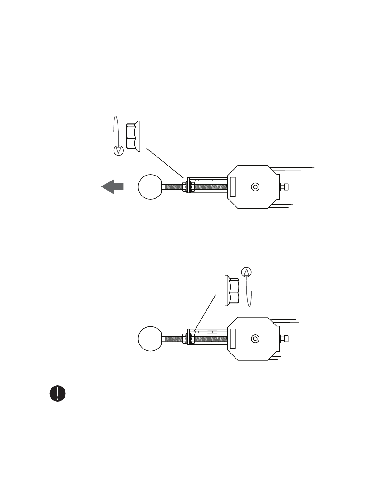
ADJUSTMENT: WIRE TENSIONER
Adjust the wire tension by pulling the ball outwards at the same time as you tighten the
tensioning bolt. Note that you have to loosen the counter nut to tighten the wire.
Finish the adjustment by tightening the counter nut.
Important: It is important that
the feed unit has the right wire
tension to work satisfactorily.
Tighten the wire until it stops
slipping in the pulley. The wire
tension may need to be readjusted
after a period of use.
Page 24
24
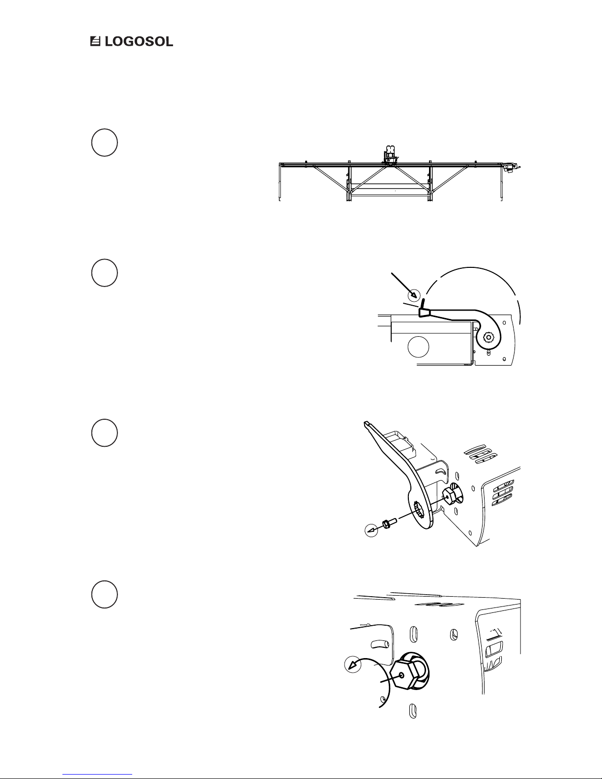
ADJUSTMENT: NEUTRAL MODE
Position the saw unit at the centre of the
guide rail.
Check that the control lever is in its
neutral position.
Unscrew the lock bolt from the control
lever to reach the pressure bolt.
Loosen the pressure bolt.
1
2
3
4
Neutral mode
Page 25
25
OPTIONAL ATTACHMENT ELECTRIC FEED UNIT
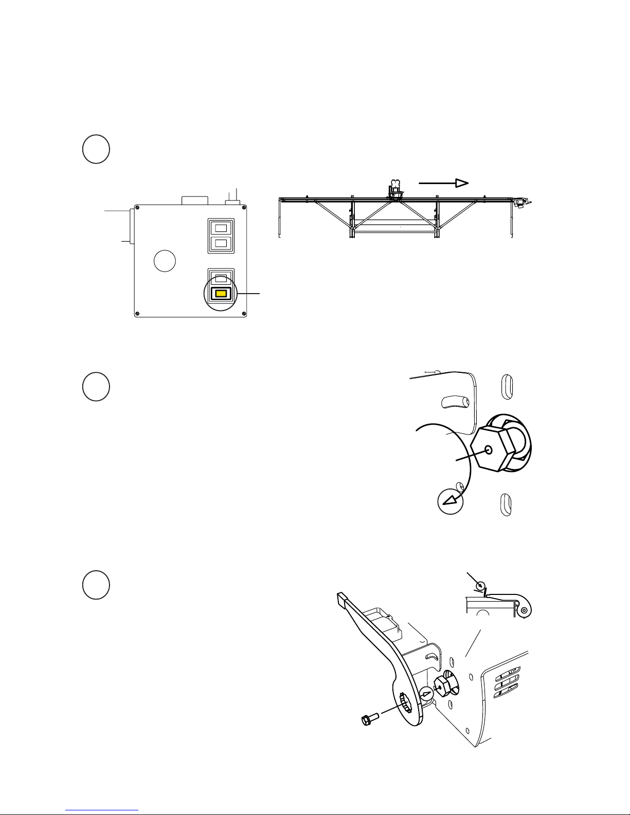
ADJUSTMENT: NEUTRAL MODE
Press the B4: reverse feed button on the control panel.
B4: Reverse feed
Tighten the pressure bolt until the saw unit just begins
to move backwards. When this happens, you loosen the
bolt slightly until the saw unit stops again.
Reinstall the control lever in its
neutral position.
5
6
7
Tip: Uses the control lever as a tool to
facilitate adjusting the pressure bolt.
Neutral mode
Page 26
26
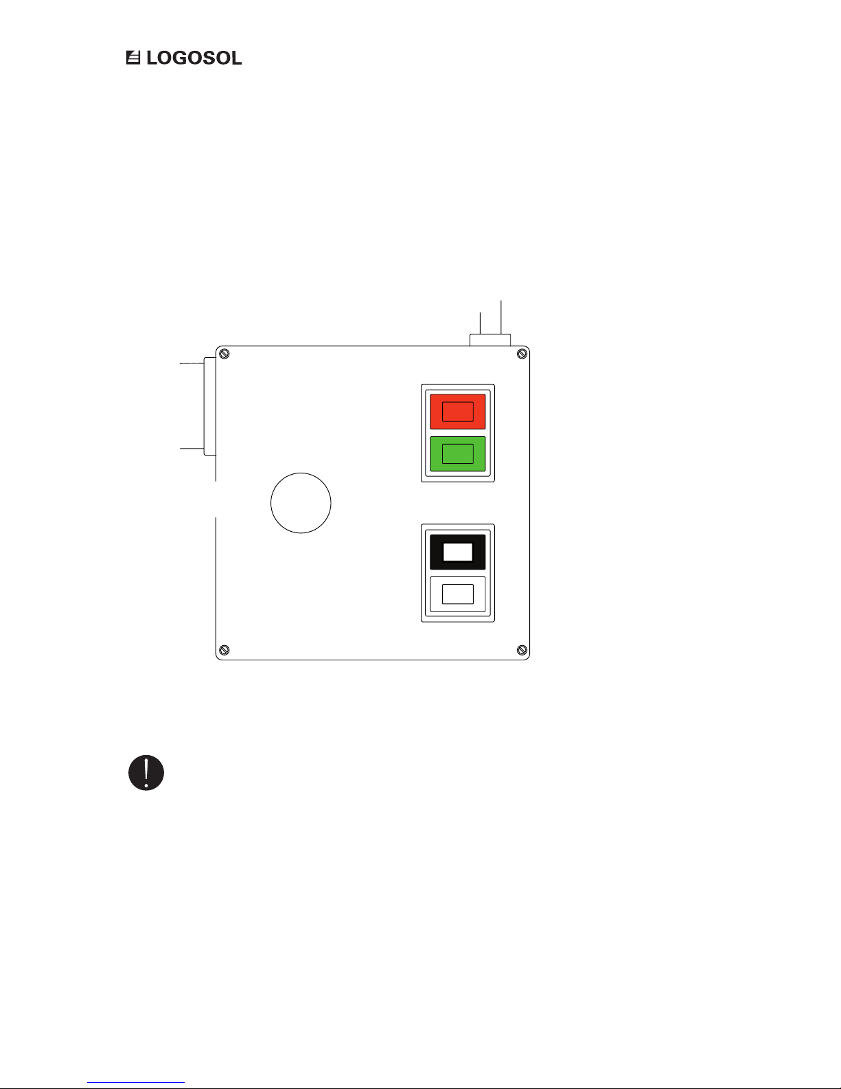
CONTROL PANEL
B1
B
2
B3
B
4
B5
Important: An enabling switch button
is a pressure-sensitive switch. It has to be
pressed down all the time during sawing
and forward feed.
Black: –
White: Start
Red: Stop
Green: Start
With the control panel buttons you choose the desired function. During all types of forward
processing you need to keep the enabling switch pressed down to enable operation.
Feed unit
Enabling
switch
Saw unit
Page 27
27
OPTIONAL ATTACHMENT ELECTRIC FEED UNIT
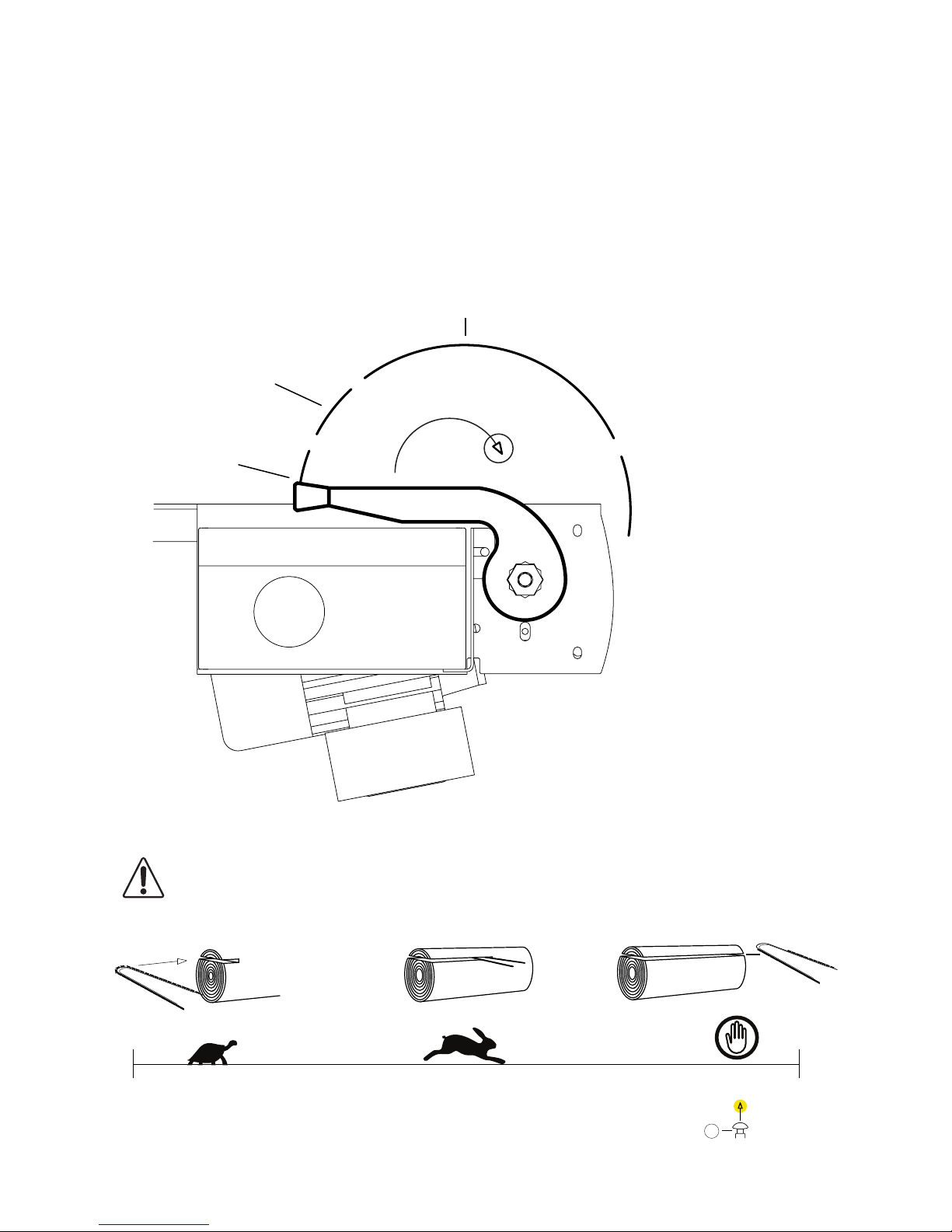
CONTROL LEVER
Danger: When starting the feed unit, the control
lever should always be in its neutral position.
With the control lever you control the feeding speed.
Operation
mode
Slip mode
Neutral mode
Slip mode
Operation mode
Stop
Page 28
28
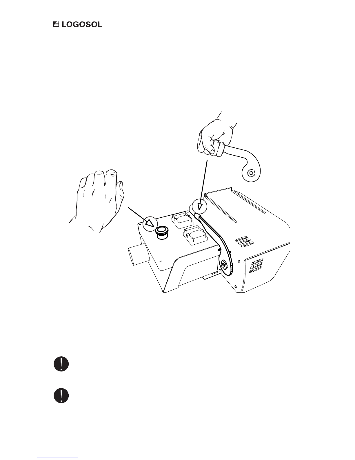
Important: When using the saw unit and
forward feed, the enabling switch button
has to be pressed down.
B2
B4B5
Hålldon
Manöverspak
OPERATION: FORWARD FEED
For forward feed, press down the enabling switch button, B5, with your left hand. With your right hand
you rst start the saw unit by pressing the B2 button, and then start the feed unit by pressing the B4 button. After that, you slowly pull the control lever with your right hand.
Important: To lower the stress on the
equipment, it is important that the saw unit
slowly enters the wood that is to be cut.
Control lever
Enabling switch
button
Page 29
29
OPTIONAL ATTACHMENT ELECTRIC FEED UNIT
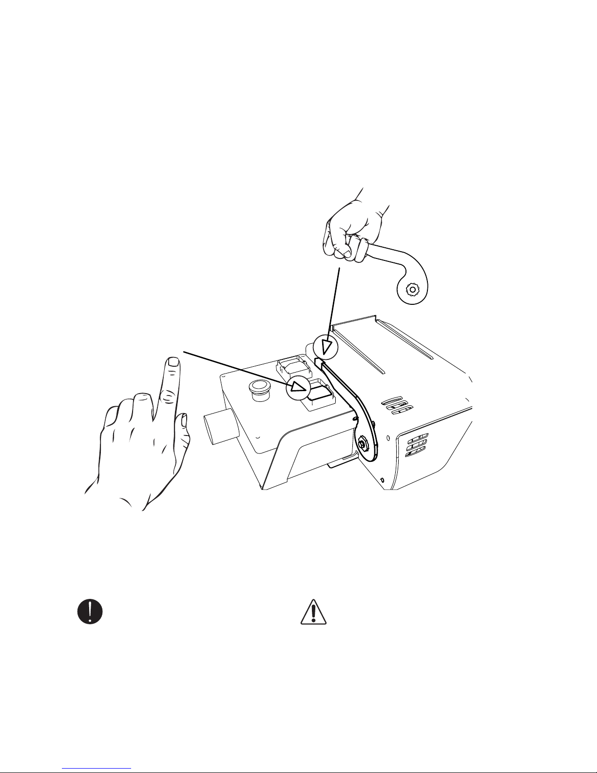
Important: During reverse feeding the B4
button has to be pressed down.
Danger: Risk of crushing and cutting
injury when the saw unit backs in over
the loading ramp.
Manöverspak
B4
OPERATION: REVERSE FEED
For reverse feed, press down the B4 button with your left hand while the control lever is pulld back with your
right hand.
Control lever
Page 30
30
The rst hours of operation, the feed unit can run
unevenly. The wire may need to be retightened a
couple of times before it becomes fully stretched
out, and it takes some time for the friction disc to
be worn into the discs before full feeding pressure
is attained. Also, the feeding pressure can pulsate a
little, but this will decline in the course of time. If the
pulsation become worse or does not decline after a
couple of hours, read the section ’Trouble shooting’
or contact Logosol.
Normally, the control lever has to be adjusted a
couple of times during the rst working day.
Important: Regularly check that no
sawdust is building up in the pulleys. Be
extra attentive when it rains, or when
extremely wet or resinous timber is sawn. If
this is overlooked there is risk that the wire
wriggles off. Clean the pulleys with a thin
piece of rigid plastic, or the like. Do not use
tools of steel.
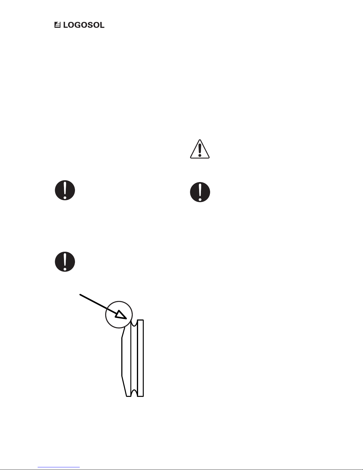
Important: Regularly check the wear in
the track in the secondary clutch disc (see
exploded view on p.35). This is a detail that
will wear over time, and will need to be
replaced at regular intervals.
Other maintenance
Cover the feed unit and the saw unit when they are
not being used.
Long-term storage: Clean the feed unit and lubricate
the ball bearings. Store the feed unit in a heated
place to prevent condensation caused by variations
in temperature.
When removing the paint on the top of the loading
ramp: Rub off rust and paint akes, wipe off with
ethyl alcohol, and paint with black paint in order to
keep the feed unit nice and clean.
Make sure that the label on the top of the loading
ramp is intact and legible. If not, order a new label.
Important: Check that there is no water
in the system. The control panel and the
motors have a drain plug or a bolt that
can be opened to drain out any water that
have accumulated. The control panel drain
plug is located on the underside of the
panel. On the feed motor it is located on
the side of the motor. On the elcetric saw
it is either located at the belt pulley or on
the side of the motor. Accumulated water
in the equipment does not constitute a
reason to make complaints.
Condensation
If the feed unit and the electric saw are stored
outdoors or in an unheated place, there is risk that
water condenses in the control panel and in the
motors due to variations in temperature. Under
adverse conditions, several decilitres of water can
accumulate here.
MAINTENANCE
Danger: Risk of electric shock and that the
equipment becomes damaged.
Page 31
31
OPTIONAL ATTACHMENT ELECTRIC FEED UNIT
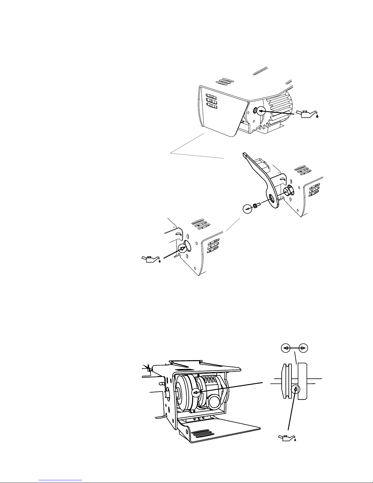
Lubrication points
Check that the ball bearings always are
lubricated. Use adhesive oil in the ball bearing
of the clutch. Be careful not to use too much
oil. One press on the adhesive oil can nozzle
gives enough lubrication (ref. no: 9999- 000-
5100). At the control lever side you remove
the pressure bolt to reach the bearing of
the secondary clutch disc. At the same time,
lubricate the friction disc on both sides to
prevent rust, and to get a smoother operation
of the feeding. This can be done by loosening
the pressure bolt about 5 mm and parting the
clutch.
Lubricate the square-shaped rubber gasket of
the 6-pole plug with a silicone lubricant (ref.
no: 9999-000-5110). This should be done
daily if the same feed unit is used for several
machines and there is heavy wear on the
gasket. Check that the gasket is not worn out
and replace it if it breaks (ref. no: 9999-000-
9999).
Lubrication of both sides of the
friction clutch and the spindle. After
maintenance is done, the neutral mode
of the feed unit must be adjusted (see
p.24)
MAINTENANCE
Page 32

32
Important: Always stop the machine if you
suspect that something is wrong with
1. the wire tension
2. the track in the clutch disc
3. the lock pins in the spindle
Important: Check the saw unit and the
cutting equipment. If the cutting equipment
does not cut as it is supposed to, it can result
in poor feeding.
The feed unit does not start:
Do you press the enabling switch button (B5) down
while you are trying to start the equipment? The
enabling switch button must always be pressed
down during sawing and forward feeding. See more
about the functions of the enabling switch under
the section Operation: Forward Feed on page 28.
Drivningen är svag:
– The feed wire is not tightened enough. Check the
tension of the wire, see Adjustment: Wire Tensioner
on page 23.
– Sawdust has accumulated in the wire track of
the secondary clutch disc. Clean the track, see
Maintenance on page 30.
TROUBLESHOOTING
Page 33
33
OPTIONAL ATTACHMENT ELECTRIC FEED UNIT
Fram/retur
Stopp
Start
M 3fasM 3fas
Matarmotor
Sågklinga
T.VG .L
SågMatare
R1
R2
Drift
Pe
K1
H.D.
Stopp
Start
Pe
A1
A2
1
24 6
14
35
13
L1
L2
L3
N
Pe
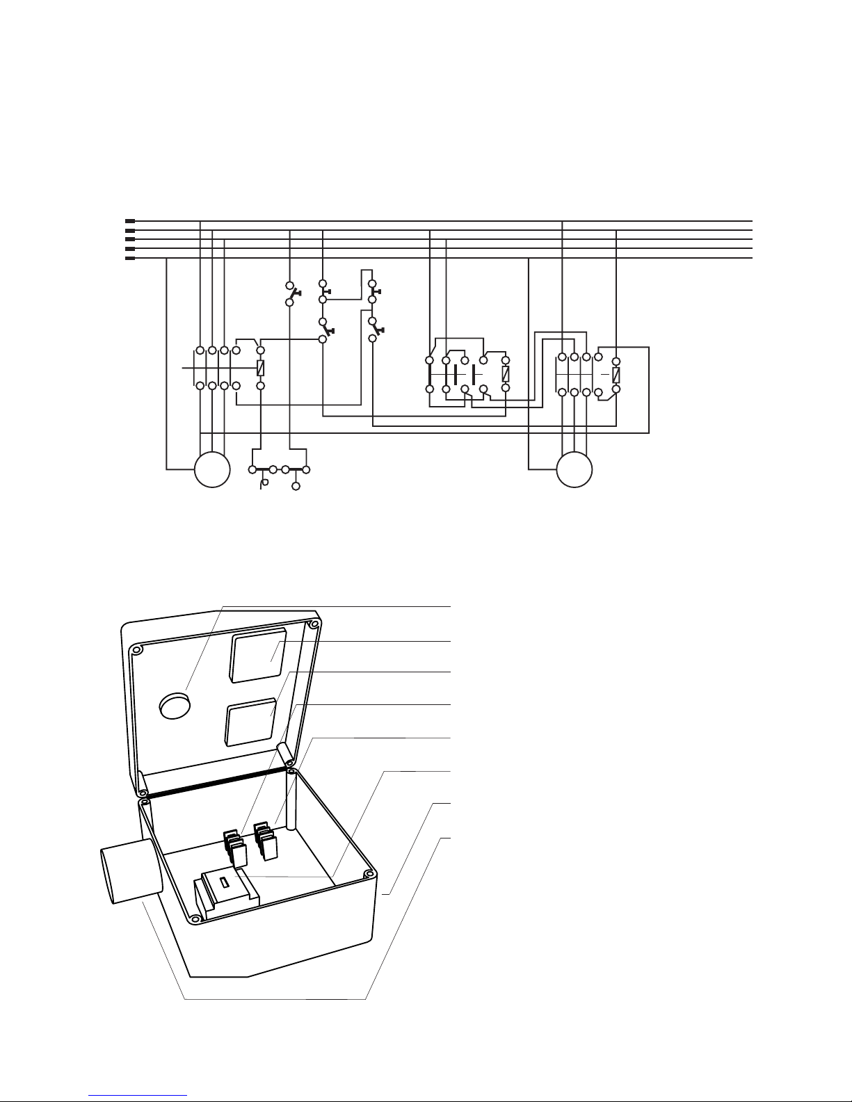
Circuit diagram
Enebling switch: 6600-001-0038
Black/white contact: 6600-001-3096
Red/green contact: 6600-001-3095
Relay: 6600-001-0402 / Norge: 6600-001-0232
Contactor: 7202-001-0160 / Noway: 7212-001-0230
Contactor: 6600-001-0045 / Noway: 6600-001-0042
Enclosure
Plug: intake with phase inverter
Electrical components list
Complete terminal box: 6600-001-3027
WIRING DIAGRAM
M
3-phase
Saw blade
Saw unit feed
Forward/reverse
Feed
Feed motor
M
3-phase
Page 34
34
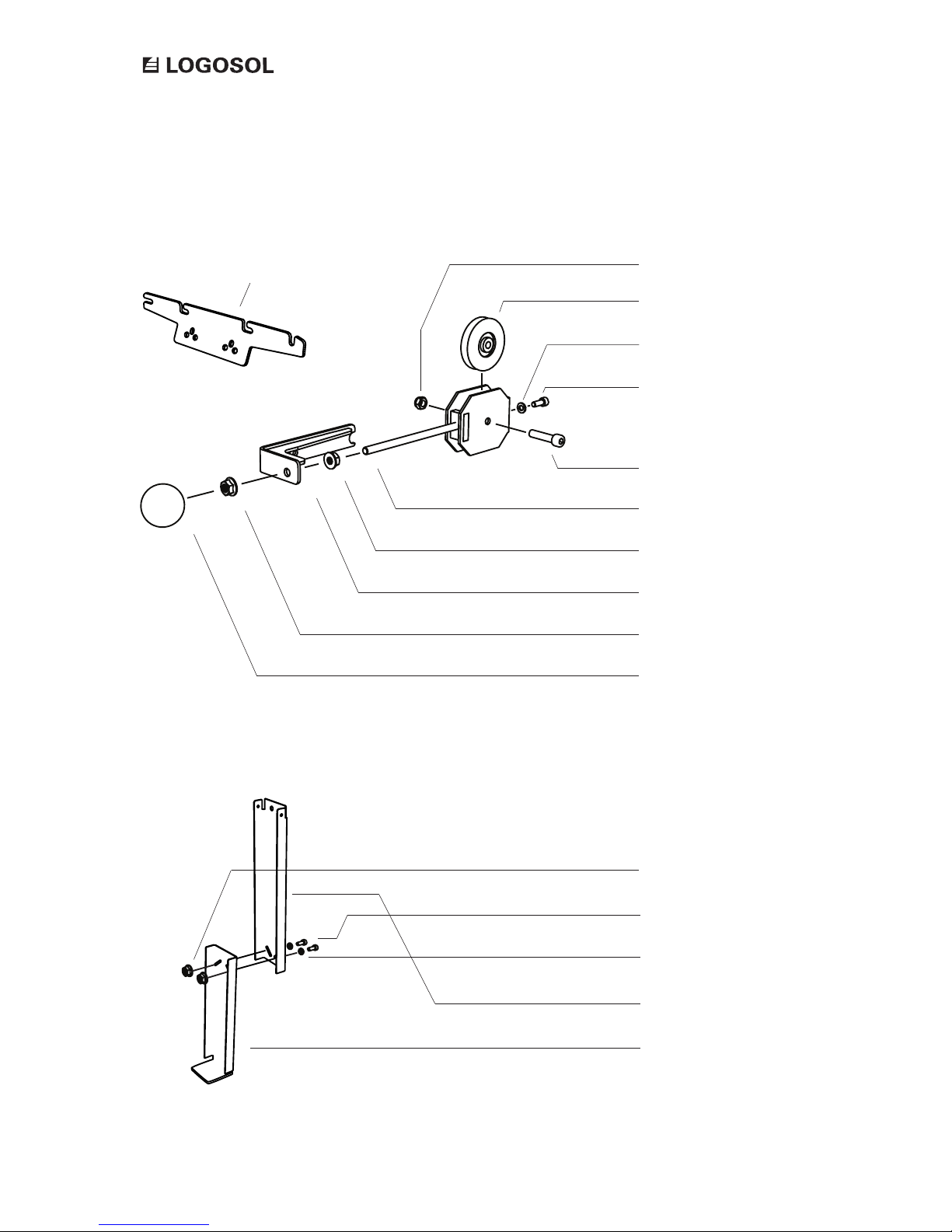
Wire attachment
EXPLODED VIEW
Lock nut M8
Flat washer M6
Allen bolt M6x16
Pulley (6600-001-3023
)
Allen bolt M8x35
Flange nut M8
Tensioner
Bracket
Flange nut M8
Ball
Flänslåsmutter, M8
Insexskruv, M8x20 mm
Planbricka, M8
Stödben, övre
Stödben, nedre
Page 35
35
OPTIONAL ATTACHMENT ELECTRIC FEED UNIT
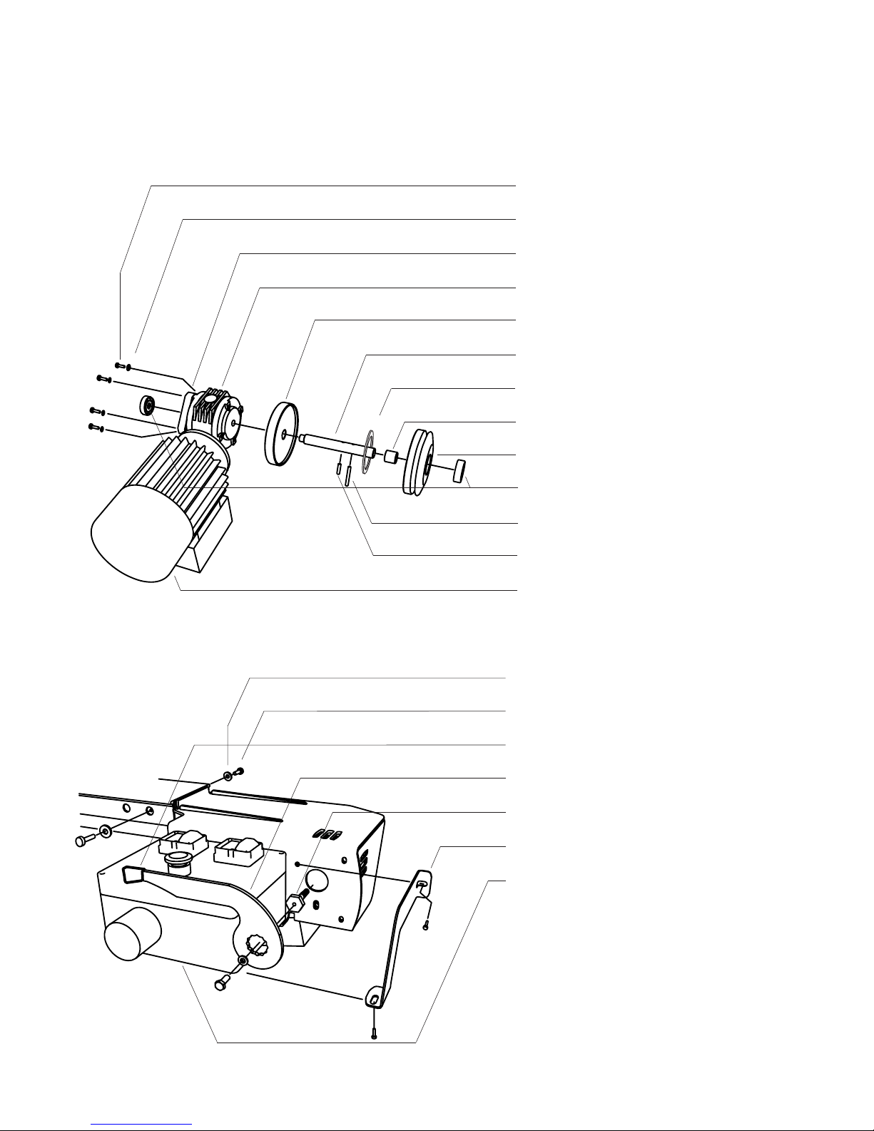
4 x Allen bolt M6x25 mm
4 x Flat washer M6
Spacer ring 12 mm
Worm gear
Primary clutch disc
Spindle
Friction disc (6600-001-3024)
Bushing
Secondary clutch disc
2 x Angular contact ball bearing (6600-001-3017)
Hardened lock pin M6x30 mm (6600-001-3018)
Hardened lock pin M6x16 mm (6600-001-3020)
Electric motor
2 x Flat washer M6
2 x Flange bolt M6x20 mm
Lever knob (6600-001-3005)
Control lever (6600-001-3027)
Pressure bolt M16/M6 (6600-001-3025)
Terminal box bracket
Terminal box
EXPLODED VIEW
Page 36

36
Page 37

37
OPTIONAL ATTACHMENT ELECTRIC FEED UNIT
Page 38

38
Page 39

39
OPTIONAL ATTACHMENT ELECTRIC FEED UNIT
EU declaration of
conformity
In accordance with Directive 2006/42/EG, Annex 2A
Logosol AB
Fiskaregatan 2
871 33 Härnösand
SWEDEN
herewith declares that the Electric Feed Unit
has been manufactured in conformity with:
The Machinery Directive 2006/42/EG
The EMC Dierctive 2004/108/EU
and has been manufactured in conformity with the following
harmonized standards:
EN ISO 12100:2010
EN 60204-1:2006
EN 50370-1, -2.
Notied body, 0404, RISE SMP Swedish Machinery Testing
Institute AB, Box 7035, 750 07 Uppsala, Sweden, has executed
EC type-examination according to Directive 2006/42/EG, article
12, paragraph 3b. The EC type examination certicate has the
number: 0404/17/2408
Mattias Byström, Product Manager, is
responsible for the technical les.
Härnösand 21/08/2018
Malte Frisk, CEO
Page 40

Fiskaregatan 2, 871 33 Härnösand, SWEDEN
+46 611-182 85 | [email protected] | www.logosol.com
 Loading...