

Page 1
You can nd this notice
on www.logo-silver.fr
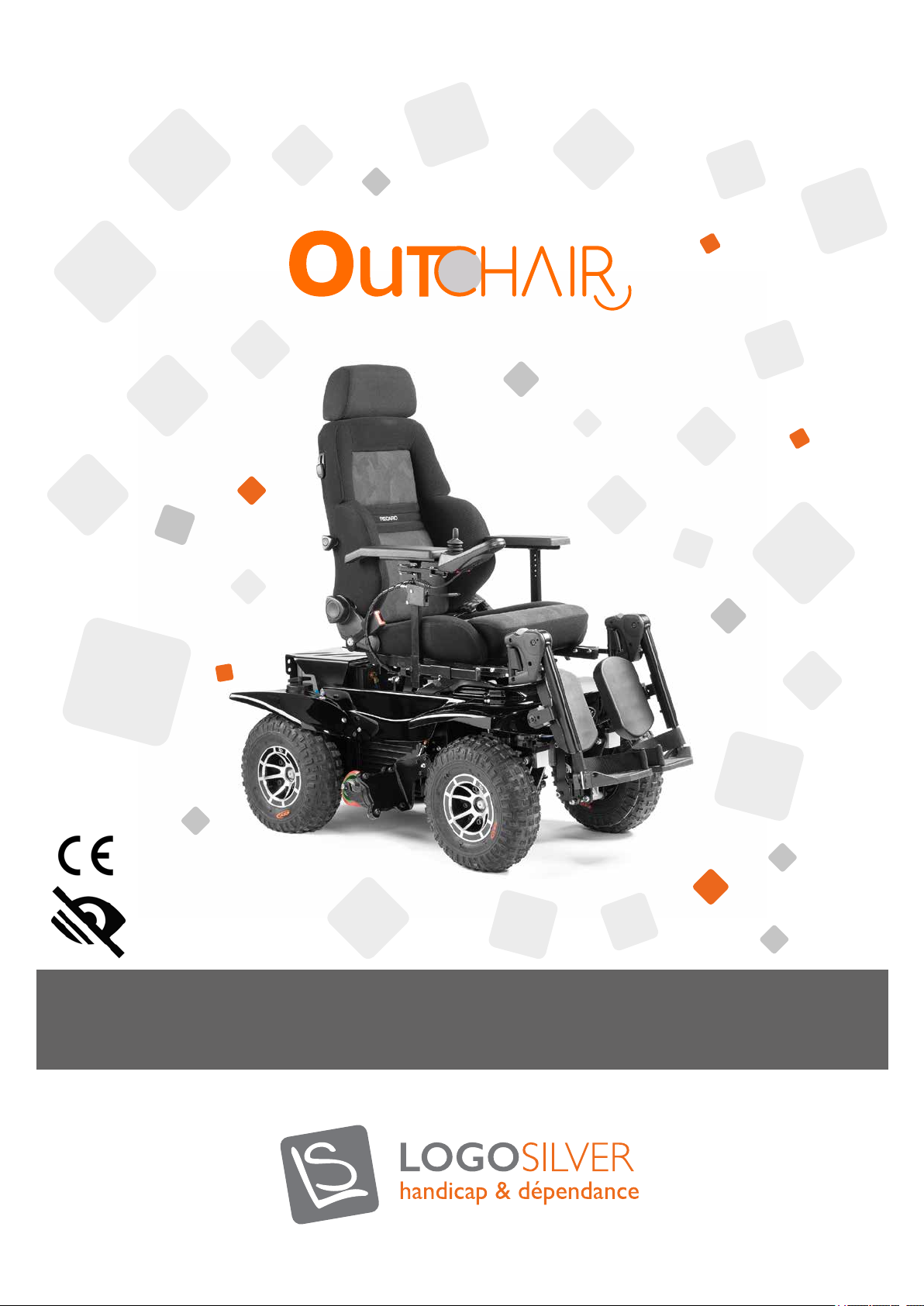
OUTCHAIR - S AND L MODELS
THE ALL-TERRAIN CHAIR.
Page 2

User manual
Summary
1. Introduction ......................................................................................................................................................................................... 4
1.1. About this manual ................................................................................................................................................................... 4
1.2. Use in accordance with instructions .................................................................................................................................. 4
1.3. Liability........................................................................................................................................................................................ 4
1.4. Indications for reuse of this product .................................................................................................................................. 5
1.5. Maintenance .............................................................................................................................................................................. 5
1.6. Contact ...................................................................................................................................................................................... 5
2. Safety ........................................................................................................................................................................................... 6
2.1. Standards and guidelines ....................................................................................................................................................... 6
2.2. Declaration of conformity .................................................................................................................................................... 6
2.3. General safety instructions ................................................................................................................................................... 6
2.4. Safety requirements for transportation, storage and assembly ..................................................................................... 7
2.5. Operation and safety requirements ................................................................................................................................... 7
2.6. Safety tips for 2 wheel drive with casters (if option available) ...................................................................................... 9
2.7. Main safety requirements for maintenance, care and disposal ..................................................................................... 9
2.8. User requirements ................................................................................................................................................................. 10
2.9. Safety functions ..................................................................................................................................................................... 10
2.10. Warning plates and nameplates ...................................................................................................................................... 10
2.11. Electromagnetic compatibility ......................................................................................................................................... 10
3. Technical features ............................................................................................................................................................................. 11
4. Product description ......................................................................................................................................................................... 12
5. Transport and storage ..................................................................................................................................................................... 13
6. Delivery and setup .......................................................................................................................................................................... 13
6.1. Delivery .................................................................................................................................................................................... 13
6.2. Initial charging and setup ..................................................................................................................................................... 14
7. Use ......................................................................................................................................................................................... 14
7.1. “Off-Road” driving prole .................................................................................................................................................. 14
7.2. “Crossing” driving prole ................................................................................................................................................... 15
7.3. “Indoor” driving prole with caster option .................................................................................................................... 16
7.4. Manual movement ................................................................................................................................................................ 16
7.5. Adjustment options .............................................................................................................................................................. 18
7.5.1. Armrest adjustment ..................................................................................................................................................... 18
7.5.2. Manual footrests ............................................................................................................................................................ 18
7.5.3. Standard seat ................................................................................................................................................................. 18
7.5.3.1. Backrest ...................................................................................................................................................................... 18
7.5.3.2. Headrest ..................................................................................................................................................................... 19
7.5.4. Shock absorber ............................................................................................................................................................. 19
7.5.5. Pneumatic pressure ...................................................................................................................................................... 20
7.5.6. Seat tilt ............................................................................................................................................................................ 21
7.5.7. Normal seat position when driving .......................................................................................................................... 21
7.5.8. Joystick position ............................................................................................................................................................ 22
7.5.9. Folding RECARO backrest (optional) ....................................................................................................................... 22
7.6.Transferring into the chair .................................................................................................................................................. 23
7.7.Switching the power on and off ........................................................................................................................................ 24
7.7.1. Protection of the electronic system ........................................................................................................................ 24
7.7.2. Circuit Breaker fuse ..................................................................................................................................................... 24
7.7.3. Switching the power on .............................................................................................................................................. 24
7.7.4. Switching the power off .............................................................................................................................................. 25
7.8. Joystick control ...................................................................................................................................................................... 25
7.8.1. Joystick ............................................................................................................................................................................. 25
7.8.2. Powering the joystick .................................................................................................................................................. 25
7.8.3. Rain and water .............................................................................................................................................................. 25
7.8.4. Joystick cable ................................................................................................................................................................. 25
7.8.5. The control programme .............................................................................................................................................. 25
7.8.6. Precautions for use ......................................................................................................................................................... 26
2
Page 3

7.8.7. Joystick LCD ................................................................................................................................................................................ 26
7.8.7.1. Control panel ............................................................................................................................................................. 26
7.8.7.2. Control system indicators on the LCD screen ................................................................................................. 27
7.8.7.3. Basic programming and conguration .................................................................................................................. 28
7.8.8. Joystick CJSM2-BT (optional) ...................................................................................................................................... 30
7.8.8.1. Control system information ................................................................................................................................... 30
7.8.8.2. Instructions on the control system scre ............................................................................................................... 30
7.8.8.3. Basic programming and setup ................................................................................................................................ 33
7.8.8.4. CJSM-BT pairing ........................................................................................................................................................ 34
7.8.8.5. “Discovery” mode .................................................................................................................................................... 34
7.8.8.6. Infrared (IR) control ................................................................................................................................................. 35
7.8.9. Locking the control system ........................................................................................................................................... 37
7.8.10. Screen ............................................................................................................................................................................ 38
7.9. Driving tips ............................................................................................................................................................................. 38
7.10. Batteries and recharging ................................................................................................................................................. 38
7.10.1. Batteries ........................................................................................................................................................................ 38
7.10.2. Charging the batteries .............................................................................................................................................. 39
7.10.3. Breaking-in the battery ............................................................................................................................................. 39
7.10.4. Charging process ........................................................................................................................................................ 40
7.10.5. Battery gauge .............................................................................................................................................................. 41
7.10.6. Public transport .......................................................................................................................................................... 41
7.10.7. Disposal and recycling of batteries ........................................................................................................................ 41
8. Options ......................................................................................................................................................................................... 42
8.1. CJSM2 joystick with Bluetooth .......................................................................................................................................... 42
8.2. Electric leg lifts ...................................................................................................................................................................... 42
8.3. Steering lock .......................................................................................................................................................................... 42
8.4. Casters ..................................................................................................................................................................................... 42
8.5. Batteries ................................................................................................................................................................................... 43
8.6. RECARO seat ........................................................................................................................................................................ 43
8.7. Other optional components .............................................................................................................................................. 43
9. Malfunction and troubleshooting ............................................................................................................................................. 43
9.1. Diagnostics and troubleshooting ........................................................................................................................................ 43
9.2. Solving common problems ................................................................................................................................................. 44
10. Maintenance and care ................................................................................................................................................................ 45
10.1. General recommendations ............................................................................................................................................. 45
10.2. Protection against corrosion .......................................................................................................................................... 46
10.2.1 Peeling paint ................................................................................................................................................................. 46
10.2.2 Beach, salt water and coastal areas ........................................................................................................................ 46
10.2.3 Snow and ice, salt roads and paths ......................................................................................................................... 47
10.2.4 Cleaning after use ....................................................................................................................................................... 47
10.2.5 Preventative care ........................................................................................................................................................ 47
10.3. Daily checks ....................................................................................................................................................................... 47
10.4. Weekly checks ................................................................................................................................................................... 47
10.5. Monthly checks ................................................................................................................................................................. 48
10.6. Annual check ..................................................................................................................................................................... 48
10.7. Repairing a tyre/air chamber .......................................................................................................................................... 48
10.8. Battery replacement ........................................................................................................................................................ 50
10.8.1 Battery removal .......................................................................................................................................................... 50
10.8.2. Reassembling the batteries ...................................................................................................................................... 53
10.9. Seat tilt malfunction ......................................................................................................................................................... 54
10.10. Caster (optional) malfunction ....................................................................................................................................... 54
10.11. Steering lock (optional) malfunction ........................................................................................................................... 55
10.12. Cleaning the vehicle ........................................................................................................................................................ 55
11. Warranties ..................................................................................................................................................................................... 56
12. Disposal ......................................................................................................................................................................................... 56
3
User manual OUTCHAIR
09/2018
Page 4
User manual
1. Introduction
1.1. About this manual
First of all, we would like to thank you for your condence in our products. We hope that your new 4x4 electric wheelchair will
bring you a lot of satisfaction.
This Owner’s Manual provides the user and attendant with all the necessary knowledge regarding the safety, use, construction,
and maintenance of the Out Chair. The operating manual contains information necessary for the safe use of this 2 or 4-wheel
drive vehicle and provides information on how to identify the cause of possible malfunctions plus how to eliminate them.
It is imperative that you read the contents of this user manual in order to use the Out Chair in complete safety. The user
and attendants must read this manual carefully before using the wheelchair for the rst time. This ensures that the Out Chair
performs to its fullest capacity in complete security.
If you have questions or are unsure of whether your wheelchair is in optimal operating condition, call your dealer or contact us.
Wheelchair users have many different needs. It is up to qualied medical personnel to decide whether the model is suitable for
your particular situation.
We decline any responsibility in the case of a wheelchair being maladjusted for the handicap of the user.
We are not responsible for damages resulting from failure to observe the user guide, improper maintenance or abnormal use.
In general, our responsibility is limited to the replacement of defective parts.
Some adjustments and maintenance work require specialized technical training and must be performed by your dealer or an
authorized representative.
This user manual has been developed based on standard NF EN 62079 «User manual design - structure, content and presentation».
It comprises 11 chapters.
Pictograms and warning terms:
Danger
Warning against
possible physical
h a z a r d s a n d d e a t h .
1.2. Use in accordance with instructions
The Out Chair is intended for the individual use of persons with total or partial motor disability of the lower limbs, providing a
safe driving performance for their independent movement outside the home.
The Out Chair must only be associated with the features mentioned in these instructions for use and vice versa. Logo Silver,
manufacturer of the Out Chair, is not responsible in the case of combination with medical devices and / or accessories not
included in the list of options and from other manufacturers.
Any use other than that mentioned is not considered to be in conformity. The responsibility for personal injury or material
damage resulting from improper use rests with the user and not the manufacturer.
Only duly informed persons can use the Out Chair. Being informed of the operation of the Out Chair is one of the conditions
in place to use the Out Chair properly and safely and to protect people from potential hazards.
1.3. Responsibility
The liability of the manufacturer can only be incurred if the maintenance, operation and care instructions and servicing intervals
of the Out Chair are observed. The manufacturer expressly states that only spare parts authorized by the manufacturer may
be used. Logo Silver refuses all liability for damages arising from the use of unauthorized parts by the manufacturer and damage
resulting from use not in accordance with the instructions. This warranty is subject to French civil and commercial law.
Notes
Important tips and
information.
Warning
Warning against
possible material
damage.
Environment
Note on the protec-
tion of the environ-
ment.
Crash test
Warning the
OUTCHAIR has not
been tested.
4
Page 5
1.4. Indication for the reuse of the product
The Out Chair has been designed to be reused.
As with all used machines or vehicles, reused products are subject to particular constraints. The modication of features and
performance must not compromise the safety of persons during the life of the product.
Due to market observation and the state of the art, the manufacturer has evaluated the use of the Out Chair as 6 to 8 years,
provided that it is used in accordance with the instructions and that the care and maintenance guidelines are followed. This
duration does not take into account storage times at the manufacturer or at the supplier. It should be noted that if the Out
Chair is maintained according to the instructions, it will be dependable beyond the period dened above.
In order to be reused; the Out Chair must rst be cleaned thoroughly. Then the condition, wear and damage of the Out Chair
must be checked by an authorized specialist. All worn or damaged parts and components that do not t or are not suitable for
the new user must be authorised by Logo Silver and replaced depending on the options available.
The maintenance manual contains a schedule of the maintenance operations to be carried out for each model as well as detailed
information on the list of necessary tools.
1.5. Maintenance
Overhaul and repair of the Out Chair must only be performed by qualied personnel approved by Logo Silver. In case of problems,
please contact the specialist retailer who was responsible for the sale.
If you have any questions or cannot resolve the problem despite the help provided in the user manual, please contact the Logo
Silver after-sales service (see part 1.6 Contact)
In the interest of its customers, Logo Silver strives to be of help on all levels so that the Out Chair can be enjoyed for years to
come.
1.6. Contact
For all questions regarding this material, please contact your supplier rst. If you want to contact us directly, here are our
contact details:
- Silver Logo, 32 rue de Comboire, 38130 ECHIROLLES, France
- Phoning from France: 0476212219
- Phoning from abroad: +33476212219
- Email: [email protected]
5
User manual OUTCHAIR
09/2018
Page 6
User manual
2. Safety
2.1. Standards and guidelines
All safety information in this manual relates to the current French legislation and the provisions of the European Union. In other
countries, the relevant legislation and provisions must also be respected.
The Out Chair has been manufactured in accordance with current technical regulations for safe operation. The safety of the Out
Chair is certied by the CE marking, the declaration of conformity is certied according to EN 12184.
2.2. Declaration of conformity
As a manufacturer, Logo Silver declares under its own responsibility that the Out Chair complies with specications 93/42 and
2007/47 relative to the European directives for medical devices.
The design, development and manufacture of the Out Chair are in full compliance with safety with the following technical
requirements:
Risk analysis and management according to NF EN ISO 14971 standards
Design requirements NF EN 12182 and NF EN 12184
Dynamic Stability, Static Stability, Fatigue Testing, Static load promotional literature, Use and Maintenance Guide, Labelling,
Determining Energy Consumption, Determining Speed, Acceleration and Deceleration, ability to climb the maximum safety
slope, ability to climb obstacles.
Compliance with the NF EN 12184 standard means among other things that the values required for an incline, an obstacle
crossing, and a speed are reached or exceeded by the Out Chair.
2.3. General safety instructions
•
The Out Chair can only be used in accordance with instructions.
Only duly informed and authorized persons can use the Out Chair.
•
Only one person at a time can travel in the Out Chair.
•
For safety reasons, it is imperative that the user always wears a helmet and fastens their seat belt.
•
All safety instructions contained in this operating manual and in all valid associated documents must be observed and
•
followed. This notice must be available to the user at all times.
The cushion and the backrest fabric are not easily ammable but can catch re. The use of re or a lit cigarette should
•
be exercised with extreme caution.
The mode and prole changes; outdoor, indoor, crossing, seat position, backrest, casters, footrest and low to high speed
•
must all be done at a standstill.
• Check that the motors are engaged to allow the wheelchair to activate.
Only the manufacturer’s original components or options may be used. The optional components must be mounted
•
exclusively by a technician authorised by Logo Silver. Failure to comply with this recommendation will result in loss of
warranty rights.
Do not use the wheelchair under the inuence of alcohol, drugs or any other narcotics restricting your driving ability.
•
Use the seat belt, especially when you do not have sufcient back support, or when you are on uneven ground.
•
Do not lean forward, over the sides or over the top edge of the wheelchair, especially if the ground is sloping.
•
• To transfer, get as close as possible to the new seat.
Do not connect any electrical equipment to your wheelchair. Entrust any potential installation to your supplier.
•
This chair has several moving parts driven by powerful cylinders. Be careful that people around you do not get hurt. Be
•
careful in particular of children’s ngers, which may be crushed by the wheel lift system and seat tilt system.
Do not go out unaccompanied or without a means of reaching someone you trust for journeys in isolated areas or when
•
the weather conditions are very bad.
6
Page 7
2.4. Safety requirements for transportation, storage and assembly
•
Only lifting equipment of a sufcient size may be used for transport.
The Out Chair must be transported in “wooden crate” packaging, designed by the Logo Silver company, or in packaging
•
approved by Logo Silver, or transported in another vehicle, xed with a sufcient number of straps. The Out Chair must only
be lifted by the frame parts.
• During transport, the electrical part of the Out Chair will be switched off via the Joystick. The engine brakes will then
be locked.
It is forbidden to travel seated in the Out Chair during transport.
•
It is essential that the chair be attached with straps to the 3 anchor points provided for this purpose.
•
To ensure a lifetime from your Out Chair, it should be stored in a safe place protected from moisture and extreme
•
temperatures (between +5° and +30 ° maximum).
After each adjustment or settings change made to the Out Chair, the fastening screws and nuts must be screwed back
•
in rmly.
Avoid loading the wheelchair into a vehicle with the driver still in the chair.
•
If the wheelchair needs to be loaded in with its driver via a ramp, an attendant must stand by the wheelchair to avoid it
•
tipping over. When using a ramp, a maximum speed of 3 km / h should be applied.
Do not use the electric wheelchair as a seat in a vehicle.
•
2.5. Operation and safety requirements
The user has the obligation to ensure, before each use, that the Out Chair is in a safe state and in accordance with the
instructions, including the safety functions. The Out Chair should only be activated if all safety functions, such as the brakes, are
in working order. Defective brakes can cause serious accidents and injuries that can put the user’s life at risk.
•
Do not exceed the speed limits indicated in the technical specications section.
Only one person at a time can use the chair.
•
The operational and safety conditions of the Out Chair must be checked at least once a year by an authorized specialist.
•
If any errors, faults or other hazards that could cause personal injury are detected, the Out Chair must be taken out of
•
service immediately.
The Out Chair only works at temperatures of between +5 ° C and + 35 ° C. When operating, the Out Chair should not
•
be exposed to temperatures above or below those listed above.
The maximum load supported by the Out Chair is 140 Kg. This user weight should not be exceeded.
•
Before each use, a visual inspection must be carried out to check that the groove depth and the tyre pressure are
•
sufcient (see tyre wear indicator).
The chair must be turned off when making transfers..
•
Obstacles such as sidewalks must be crossed perpendicularly at a moderate pace following the procedure described in
•
section 7.2. Driving Prole “Crossing”.
Do not cross over obstacles greater than 4 cm when driving uphill and downhill.
•
The Out Chair can be driven on ascents and descents of 10 °. It is forbidden to drive on ascents or descents whose
•
inclination is greater than this limit.
For safety reasons, when driving on a descent greater than 5 °, reduce the speed to 5km / h, avoid braking suddenly and
•
have a seat inclination of 10 ° toward the rear.
For safety reasons, when driving on an ascent greater than 5°, reduce the speed to 5km / h, avoid accelerating suddenly
•
and have a seat inclination of 0 ° and the backrest as vertical as possible.
Do not drive the wheelchair on side slopes greater than 5°.
•
In 4 Wheel Drive, on most ground, use the outdoor prole, the «crossing» prole is only useful to clear obstacles (e.g.
•
pavements).
7
User manual OUTCHAIR
09/2018
Page 8

User manual
• Manoeuvres must only be performed at reduced speeds.
Mode changes such as seat, backrest, caster and footrest positioning, low and high speeds must be performed at a
•
standstill.
If you need to brake in an emergency, simply release the control lever; this will bring the wheelchair to a standstill. If you
•
brake by pushing the joystick backwards or pressing the start / stop button, it causes a sudden and violent stop.
Approach right angle obstacles in forward gear.
•
Never descend or climb an obstacle in reverse.
•
The ground clearance of 10 cm does not allow for the crossing over of a stone, for example, greater than 10 cm when in
•
the centre of the wheels, as you could damage the undercarriage of the chair.
When crossing over an obstacle (sidewalk for example), use the “crossing” mode, cross the front wheels over it gently
•
(2km / h maximum). Follow the procedure in chapter 7.2. driving prole “crossing”.
Never attempt to climb or descend stairs greater than 1 step.
•
If there is a risk of skidding on the sloping ground, stop the wheelchair before it skids and leaves the wheelchair in a
•
position that would prevent you from restarting.
• If you have the steering lock option, it is advisable to use it to lock the right wheels when crossing over obstacles, uneven
ground, or when you lack traction (skidding).
Do not sit in, get out of or park the chair without turning off the electrical system. This will prevent you from activating
•
the chair accidentally.
When getting out of the wheelchair, avoid putting all of your weight on the footrests.
•
The chair could tip forward, especially if the ground is on a slope.
•
Do not leave your seat on a slope.
•
Do not use the «indoor» mode when the casters are retracted, as it is not optimized for 4WD use.
•
Electronics such as the joystick, the power module, and the Out Chair’s connectors are protected according to the
•
protection class IP54 (protection against dust and some water splashes) but cannot, therefore, be used in bad climatic
conditions (example: in case of rain).
The Out Chair may generate electromagnetic interference that may disrupt the operation of other devices. Therefore, it
•
is best to turn off the power when not in use.
Regarding the tyres, the following observations must be taken into account:
The Out Chair’s tyres contain chemicals that may cause reactions with other chemicals (e.g. cleaning products, acid).
•
• Direct exposure to the sun (UV) accelerates tyre aging. This results in a hardening of the surface of the tyre prole that
cracks at the edges.
• Regardless of their wear, the tyres must be changed every 5 years.
• Prolonged use or heating of the tyres (if the Out Chair is near a radiator or exposed to sunlight through a window) causes
permanent deformation of the latter. Therefore, be sure to keep sufcient distance from heat sources.
Charging batteries can produce short circuits. Therefore, the following safety precautions must be taken: chair must be
•
off (joystick and reinforced circuit breaker off).
• Be careful not to put the plus or minus parts of the battery in contact due to risk of being exposed to an electrocution and
/ or burn.
Check the function of the front wheel shock absorbers.
•
During outings in the forest, be careful not to scratch (legs, hands, arms etc) with branches, stones or any other objects
•
that may cross your path.
It is strongly advised to wear a helmet, gloves, over-the-ankle shoes and long pants especially when going out on marked
•
trails.
8
Page 9
• In all cases do not exceed an angle of 20 ° relative to the vertical backrest incline while moving.
In all cases do not exceed an angle of 10 ° relative to the horizontal seat incline while moving.
•
When you’re sitting in your chair, on the public road, you are not very visible to motorists. Before crossing a road, check
•
that the ow of trafc has ended and proceed with caution.
Drive at reduced speed in cluttered or narrow passages with doors, paths bordering bushes or with stones.
•
Do not use the Out Chair in trafc lanes. Be very careful when crossing the roads.
•
2.6. Safety tips for 2-wheel drive with casters (if option available)
The retractable caster option allows you to switch from an outdoor wheelchair with 4-wheel drive to a classic wheelchair with
two-wheel drive as the retractable caster system lifts the front wheels up.
When the casters are released you must be:
• Stationary.
• On a at and level surface.
• With the front wheels straight. There is a risk of damage to the front motors, tyres and the caster system if the front wheels
are not straight when the casters are released.
• It is advisable to lock the right-hand drive if you have chosen the additional steering lock option.
• The casters must be retracted as far as they can so that the caster supports are perpendicular to the oor.
•
After the casters are retracted, use the indoor mode (see chapter 7.2. Driving Prole “Indoor”) which is optimized for
this operating mode.
Do not exceed 2.5 km / h and avoid obstacles bigger than 1 cm, this could damage the cylinder and the caster system.
•
Do not cross over obstacles greater than 1 cm at more than 1 km / h.
•
Check that the front wheels are no longer turning and do not touch the ground.
•
2.7. Safety requirements for maintenance, care and disposal
•
Out Chair maintenance must be performed by qualied personnel approved by Logo Silver. This also applies to all repairs
and adjustments carried out. An incorrect setting may void the manufacturer’s warranty and conformity assessment.
The joystick must be turned off and the batteries disconnected for all maintenance work.
•
After removing special screws, nuts or washers; replace them with identical components at all points if damaged and
•
screw them back in rmly.
The Out Chair can be cleaned with water and a soft cloth.
•
• Defective batteries must be returned to the suppliers or Logo Silver for recycling in accordance with environmental
specications.
2.8. User requirements
•
The use of the Out Chair is reserved for competent users. For this reason, the user must be instructed by qualied and
authorized Logo Silver personnel on how to operate the Out Chair.
The user must have read and understood this manual completely.
•
It is forbidden to use the Out Chair in the event of severe fatigue or under the inuence of alcohol or medication.
•
Before the rst use, practice driving the Out Chair on at ground in good visibility, then increase the difculty, with
•
obstacle crossing, descents and climbs. This training helps to avoid dangerous situations.
It is strongly advised that the user wear a helmet.
•
9
User manual OUTCHAIR
09/2018
Page 10
User manual
2.9. Security features
•
In the event of danger, the Out Chair can be switched off at any time using the joystic.
• If the engines overheat, allow the chair to cool down before restarting.
• The chargers will automatically shut off as soon as the batteries are charged (charge indicators will turn green).
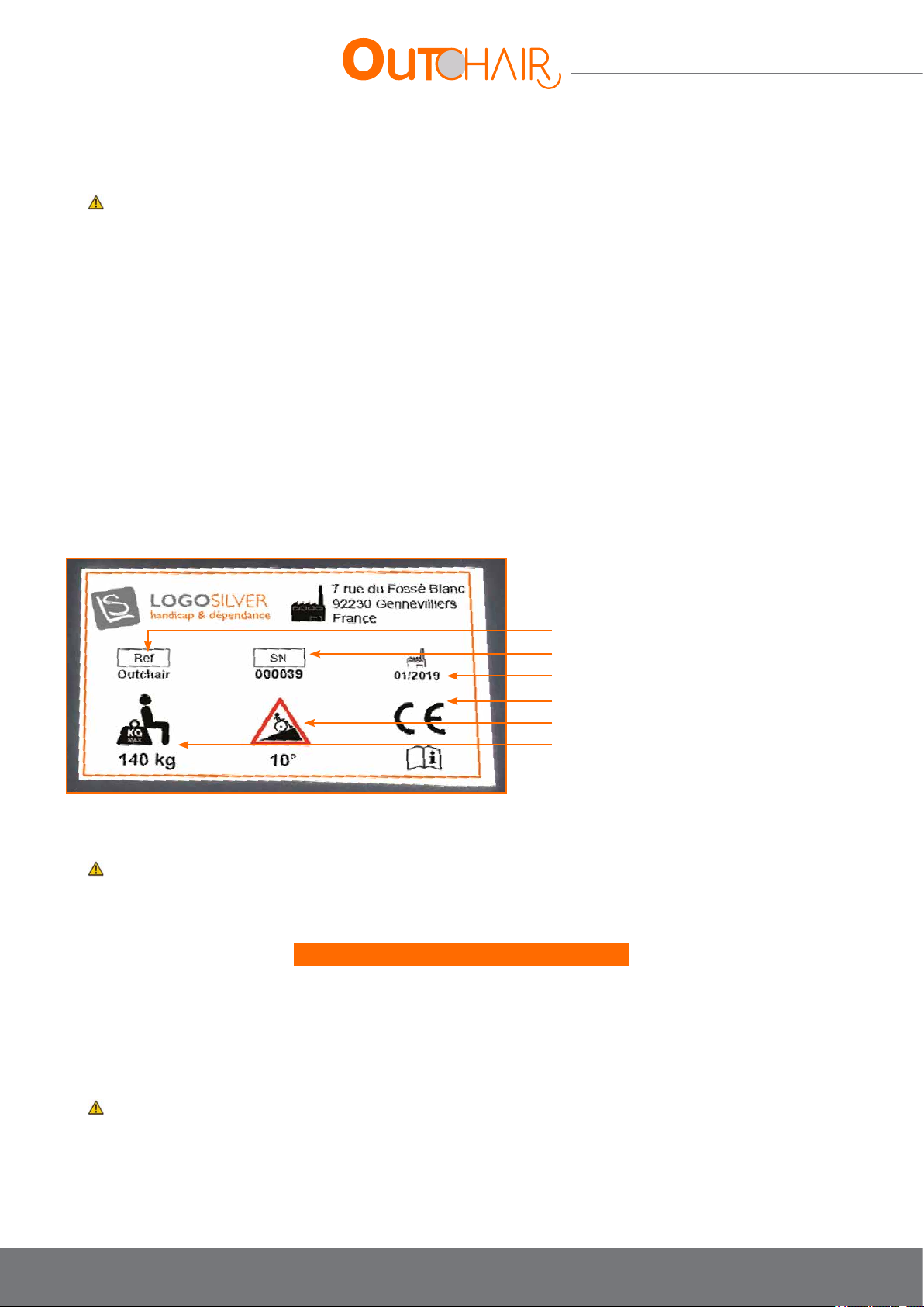
2.10. Warning plates and nameplates
• Reference
• Series number
• Date of manufacture
• CE marking
• Maximum lateral slope
• Maximum user weight
2.11. Electromagnetic compatibility
The electromagnetic compatibility of this wheelchair has been tested in accordance with international standards.
•
However, there is a risk of disruption to the wheelchairs’ electronic system in the event of proximity to a source of strong
electromagnetic radiation.
The following precautions must be taken:
• Avoid immediate proximity to powerful transmitters (radio, television, telephone).
• Check that your transmitters (mobile phones or others) have no inuence. If in doubt, only use them when the wheelchair
is turned off.
• If your vehicle should start moving by itself or if the brakes come loose, turn the wheelchair’s electronic system off as soon
as possible.
• Report to your supplier any undesired chair movements that have occurred, including the loosening of the electric brakes.
•
It should also be noted that the addition of electrical accessories can signicantly alter the chairs’ electromagnetic
compatibility.
10
Page 11
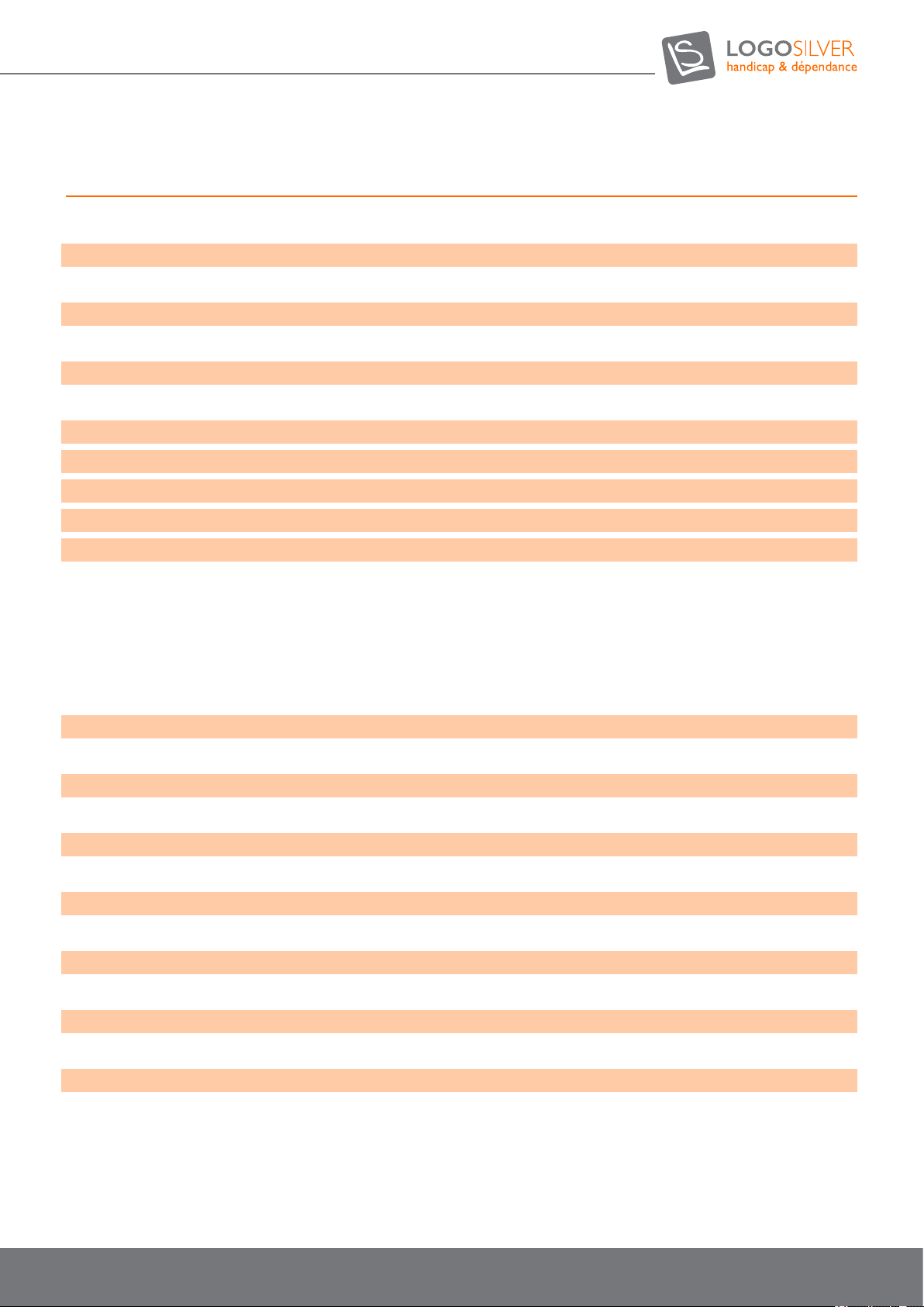
3. Technical characteristics
Total length without footrest 100 à 110 cm
Total length with footrest 113 à 123 cm
Total height standard manual seat with headrest 145 cm
Total height Recaro option with headrest 140 cm
Width 67.5 cm
Unladen weight 175 à 245 kg
Maximum user weight 150 kg
Standard manual seat:
. Seat height 62 cm
. Clear width 45 cm
. Depth 47 cm
. Backrest height 75 - 95 cm
RECARO seat option:
. Seat height 60 cm
. Clear width 47 cm
. Depth 5 0 à 57 cm
. Backrest height 77 - 83 cm
Seat angle 0° + 23°
Rear wheel diameter 35 cm (14°)
Front wheel diameter 35 cm (14°)
Turning radius 100 à 110 cm
Maximum speed 10 km/h
Maximum speed crossing prole 5 km/h
Autonomy on the at 30 à 50 km*
Wheel motors 4 x 350 w
Battery capacity 80, 110 ou 135 Ah
Off-road prole obstacle height in forward gear 4 cm
Crossing prole obstacle height in forward gear 15 cm
Crossing prole obstacle height in forward gear 1 cm
Maximum slope in forward gear 10°
Maximum lateral slope 5°
* : The range of an electric wheelchair depends on the chosen battery option, the state of charge of the batteries, the
temperature, the weight of the user, the slope, the ground surface, the tyre pressure …
11
User manual OUTCHAIR
09/2018
Page 12
User manual
4. Product description
The Out Chair is an outdoor chair. It is extremely manoeuvrable and easy to operate. Its 4-wheel
drive system is powered by 2 batteries allowing for it to cross obstacles of more than 12cm and to
climb slopes of 10 ° providing a safe driving performance.
All of the commands are at your ngertips via the joystick.
The Out Chair is characterized by:
• Its ability to adjust the seat angle
• Its ability to adjust the foot rests according to angle and length of the legs
• Its ease of transfer including retractable armrests
• Its considerable autonomy including powerful battery capacity
• Its individual adjustment possibilities thanks to the features and custom manufacturing.
Numerous options for tting or adjusting the controls make it possible to adapt the Out Chair depending on the total or partial
disability of the upper and lower limbs.
The Out Chair has been specially designed for users able to move independently with this vehicle. In addition, the following
must be considered:
• Size and weight (max load = 140 Kg)
• The physical and psychological state of the user.
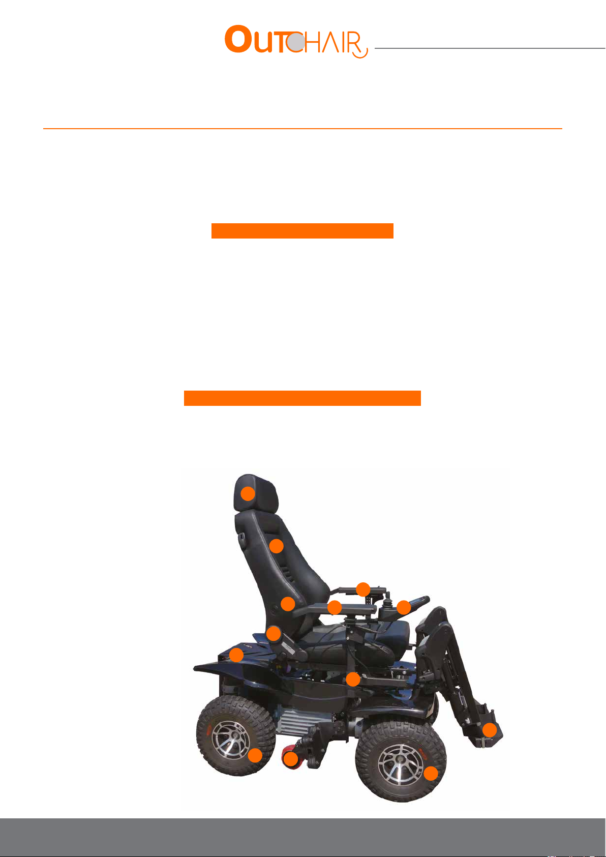
Les principaux composants de l’OUTCHAIR :
1- Headrest
2- Backrest
3- Lumbar adjustment button
4- Angle adjustment of backrest
5- Motor release levers
6- Casters (optional)
7- Drive wheels
8- Armrests
9- Joystick controller
10- Adjustment screws for armrest positioning
11- Footrests
1
2
8
3
4
5
8
10
9
11
7
6
7
12
Page 13
5. Transport and Storage
Danger
Risk of injury in the event of improper transport!
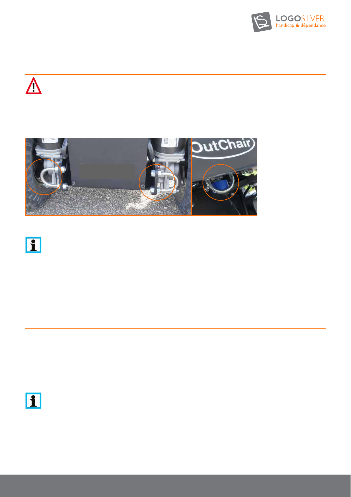
The Out Chair must be strapped to the vehicle’s anchorage points on the trailer or transport vehicle with front and / or rear
protection. The joystick must be turned off and the engine brakes locked.
Points d’ancrage
Under no circumstances can the seat of the Out Chair be used as a seat during transport.
Note
If the Out Chair remains in storage you must:
• Turn off the joystick
• Avoid direct exposure to sunlight (UV accelerates tyre aging)
• Store in a dry place with a room temperature of between +5 ° C and + 35 ° C.
Anchorage points
6. Delivery and Setup
6.1. Delivery
Delivery includes:
• An Out Chair
• Instructions for use
• A charger and a power cable for charging
• A high-pressure pump to adjust the air dampers
Note
The optional components contained in the delivery depend on the composition of the product purchased by the buyer. The Out Chair
delivered by the specialist dealer is ready to be driven. All the adjustments made correspond to the indications of the order form or are
carried out by the specialist dealer directly on site. The Out Chair is adjusted according to the personal needs of each user.
The operation of each component can be checked in accordance with Chapter 7 and 8.
13
User manual OUTCHAIR
09/2018
Page 14
User manual
6.2. Initial Charging and Setup
Before setup, recharge the batteries with the help of the charger provided by connecting the power cord to the front of
the joystick for a minimum of 5 hours, the charger indicators must be green (they can also be red: completely dead, orange:
moderately low). See charging details in chapter 7.10 Batteries and recharging
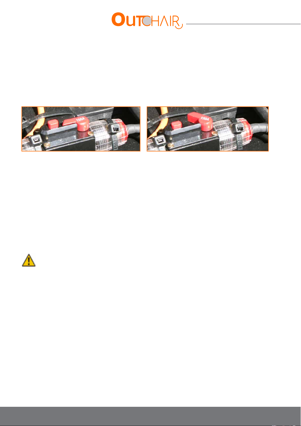
To charge the chair, make sure that the circuit breaker does not switch off the general power supply of the chair.
Activated circuit-breaker Deactivated circuit-breaker
7. Use
The Out Chair is equipped with a joystick controller to guide it.
The PROFILE button is used to navigate between the different driving proles.
It includes 2 or 3 driving proles (depending on the options chosen):
• «Off-road» prole: 4-wheel drive wheelchair propulsion, adapted to most terrain with the ability to go at maximum speed.
• «Crossing» prole: 4-wheel drive propulsion, adapted to obstacle clearance (a step, a sidewalk, etc.) with increased instant
torque and a maximum speed of 5 km / h. It is advisable to use the steering lock in crossing mode if you have the option.
• «Indoor» prole (optional): 2WD propulsion, adapted to use with indoor casters. This mode increases the gyration speed
allowing for standard control of an indoor wheelchair. It is advisable to use the steering lock in indoor mode if you have the
option.
The joystick is used to control the special features via the MODE button (seat tilt, retraction of the casters, leg rests, backrest
tilt, environmental control...).
7.1. «Off-road» driving prole
This driving prole goes at maximum speed and is most suitable for normal use on most terrains (roads, paths, sidewalks, bike
paths, forests, elds...).
Warning
Take account of the recommendations in Part 2. Safety
The maximum speed permitted is 10 km / h.
Pay particular attention on at ground or when climbing, the seat should be positioned as parallel to the ground as possible and the
back as perpendicular as possible. When going downhill the seat should be tilted 10 ° backwards (relative to horizontal) and the
backrest 20 ° backwards (relative to vertical).
The PROFILE button provides access to the «off-road» driving prole. This driving prole makes it possible to reach the highest
speed of 10 km / h when the maximum speed is selected.
Do not attempt to climb obstacles greater than 4 cm in the off-road mode with a speed greater than 3 km / h, you could damage
your wheelchair and you risk falling from your seat.
This driving prole should be used in all cases, except in the case of occasional obstacle clearance or when the casters are
retracted (if option is available).
In this prole, the acceleration is gentle allowing for the autonomy as described in the technical features.
There are 5 different driving speeds, these speeds affect the maximum speed in a straight line but also on a corner. If you are in
a conned space where you need to manoeuvre accurately, it is easier to be more precise when using a lower speed (speed 2
or 3 for example).
When you need to cross slopes, make sure that they do not have an inclination higher than those in the technical characteristics
(see chapter 3. Technical Characteristics). Make sure you are in a conguration that allows you to cross over these slopes
(sufcient adhesion, no obstacles higher than 4 cm in the slope ...).
14
Page 15
On a slope greater than 5°, take care to adopt a gentle drive, avoid jolts and braking suddenly and adjust the seat to be as stable
as possible. Do not attempt to do a U-turn on a lateral slope greater than 5°, as you could fall over sideways. If you cannot climb
a slope, try to reverse as perpendicular as possible up to it. Limit acceleration on slopes and favour an appropriate momentum.
If you have the steering lock option, it is advisable to use it to keep the wheels straight.
You will nd details on joystick control in chapter 7.8.
7.2. «Crossing» driving prole
This procedure should only be used in case you have to cross over occasional obstacles of more than 4 cm high (sidewalks,
bumps, branches ...).
Warning
Take account of the recommendations of Part 2. Safety. Do not attempt to use the off-road or indoor driving prole with speeds of
greater than 3 km / h for obstacles greater than 4 cm.
The maximum speed limits permitted to cross over obstacles are:
• 1 to 2 km / h when the front wheels are in the climbing stage (risk of tipping back if going too fast)
• 2 to 4 km / h when the front wheels are in the climbing stage (if you do not go fast enough there is a risk that the rear
wheels won’t make it over the obstacle)
• 1 to 2 km / h when descending from obstacles (to have ease of use)
Be careful, occasional obstacles must only be crossed perpendicularly and in forward gear (avoiding the slopes). The seat incline
of the chair must be as parallel to the ground as possible and the incline of the backrest as perpendicular to the ground as
possible. The safety belt must be worn at all times. Make sure to respect the technical features of the chair (see corresponding
chapter).
The PROFILE button provides access to the driving prole «crossing». This driving prole is limited to 5 km / h when the
selected speed is at its maximum for the safety and comfort of the user.
If you have the «steering lock» option, it is advisable to engage the lock when the steering is straight. (See chapter 8.3 Steering
lock).
The crossing mode makes it possible to cross over obstacles of up to 15 cm in forward gear at low speeds, as it is programmed
to have instant maximum torque and power (strong acceleration).
The procedure for mounting a major obstacle such as a sidewalk is as follows:
• Align yourself as perpendicularly as possible to the obstacle.
• If you have the steering lock option, it is advisable to switch it on once the front wheels are aligned. To align the front wheels,
you will have to advance forward slightly.
• Approach the obstacle (20 cm minimum) and change the driving prole to «crossing» mode.
• Set the speed between to 3 and 5 in order to have enough speed to clear the obstacle (this may vary depending on the
wheelchair, the driving style and the weight of the user).
• Be careful as the incline of the seat must be as parallel to the ground as possible and the incline of the backrest must be as
perpendicular to the ground as possible. This will avoid any risk of tipping backwards when crossing the front wheels over
the obstacle.
• Advance at low speed to transition to the front wheels (between 1 and 2 km / h).
• When the obstacle is underneath the centre of the chair, use this momentum to accelerate and pass the rear wheels over it
(3km / h maximum). It is necessary to accelerate, as this gives the chair the power necessary to transition to the back wheels.
• When dismounting an obstacle, position yourself as perpendicularly as possible to it and descend slowly (1 to 2 km / h).
When you are in hilly or uneven areas with obstacles of more than 4 cm in height (dips, bumps, stones, branches ...), use the
driving prole «crossing» and do not exceed 3 km / h when passing over these obstacles. If you have the steering lock option,
it is advisable to use it.
15
User manual OUTCHAIR
09/2018
Page 16

User manual
When you need to climb over slopes, ensure that they do not have an incline greater than those specied by the technical
features (see chapter 3. Technical Features). Make sure you are in a conguration that allows you to cross over these slopes
(sufcient grip, no obstacles greater than 4 cm on the slope ...). Do not attempt to turn around on a slope greater than that
of the maximum lateral slope as you could tip over sideways. If you cannot climb a slope, try as much as possible to reverse
perpendicular to it. Limit acceleration on slopes in order to keep momentum, if you do not have enough momentum, the
off-road prole will allow you to gain more. If you have the steering lock option, it is advisable you use it to keep the wheels
straight.
7.3. «Indoor» driving prole with casters option
This procedure should only be used if you need to release the casters for indoor use in order to have increased manoeuvrability
(increased turning radius).
Warning
Take account of the recommendations in part 2. Security.
Do not attempt to use the off-road driving or crossing prole when the casters are out.
Do not attempt to use the indoor driving prole when driving 4-wheel drive. The front wheels must be positioned straight when the
casters are pulled out, otherwise the engines and / or the front wheels will be damaged.
The maximum speed limits allowed to cross over an obstacle of 1 cm in the event of the use of the casters is 1.5 km/h.
Be careful not to cross over obstacles greater than 1 cm in height with the casters.
The casters are only intended for indoor use.
Make sure to have the incline of the seat as parallel to the ground as possible and the incline of the backrest as perpendicular to the
ground as possible when you are moving about.
Make sure to respect the technical features of the chair (see corresponding chapter).
The caster option allows you to switch from an outdoor chair to an indoor chair, as it allows you to switch from 4WD to 2WD by raising
the front wheels and decreasing the turning radius.
The procedure for the correct use of this option is as follows:
1. Position the front wheels straight while moving forward slightly.
2. If you have the steering lock it is advisable to use it to lock the front wheels straight.
3. When at a standstill, select the casters option with the MODE button while moving the joystick right or left.
4. Push the joystick forward until the casters have released completely.
5. When the casters are out, the front wheels are raised a few centimetres, they can no longer rotate, and the
forward gear driving speed is limited to 2.5 km / h. If this is not the case, refer to section 10.5. Caster
(optional) Malfunction
6. To use the casters, select the “indoor” driving prole, which is more suitable due to its increased rotation
speed.
7. To return to 4-wheel drive, stop and select the wheel option with the MODE button by moving the joystick
to the right or left.
8. Fully retract the casters by pulling the joystick towards you.
9. The speed limit is now disabled, and the front wheels will once again be powered (4-wheel drive). If this is
not the case, refer to section 10.5. Caster (optional) malfunction.
10. You can now use the off-road or crossing prole suitable for 4WD.
7.4. Manual movement
The wheelchair motors are equipped with magnetic brakes that prevent the wheelchair from rolling on its own when it is at a
standstill. The engine brakes are automatically tightened when the joystick is in the neutral or “off” position.
To push the wheelchair, disengage the magnetic brakes.
A lever for disengaging the brakes of the rear wheels is located above the rear engines:
• When disengaged, the engine brakes are turned off. You must therefore be careful that the wheelchair does not move in an
uncontrolled manner if the ground slopes.
• Always remember to return the release levers to the «on» position after extensive use.
16
Page 17

Motor brake release:
• Turn off the remote.
• Turn the right motor button clockwise and the left motor button counter clockwise.
Motor brake clutch:
• Turn the right motor button counter clockwise and the left motor button clockwise.
If you need to, push the wheelchair by hand to disengage the rear engines and manually position the front wheels in the desired
direction.
17
User manual OUTCHAIR
09/2018
Page 18
User manual
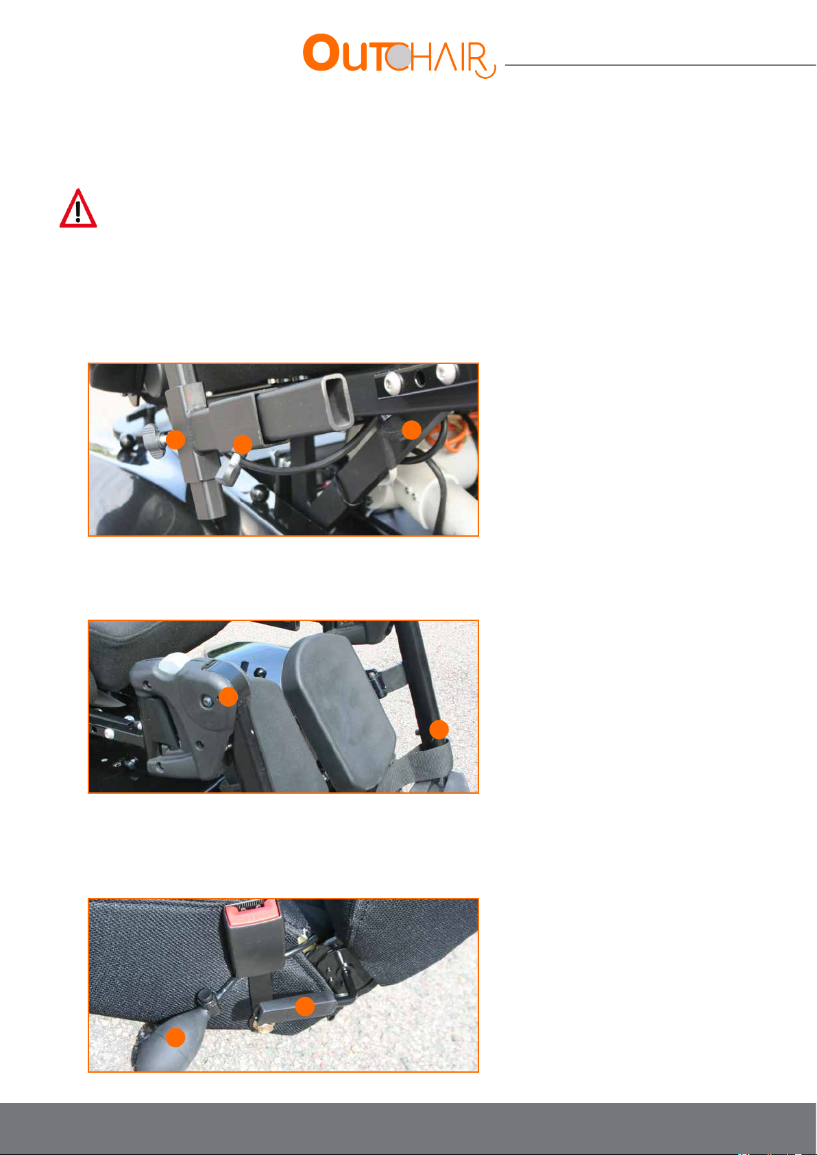
7.5. Adjustment possibilities
Danger
After each adjustment, be sure to tighten the nuts and screws securely.
7.5.1. Armrest adjustments
12 - Height adjustment of the armrest according to arm length
13 - Depth adjustment of the armrest
14 - Width adjustment of the armrest
12
7.5.2. Manual footrest
15 - Length adjustment
16 - Angle adjustment
7.5.3. Standard seat
7.5.3.1. Backrest
17 - Folding backrest
18 - Lumbar adjustment
14
13
15
16
17
18
18
Page 19
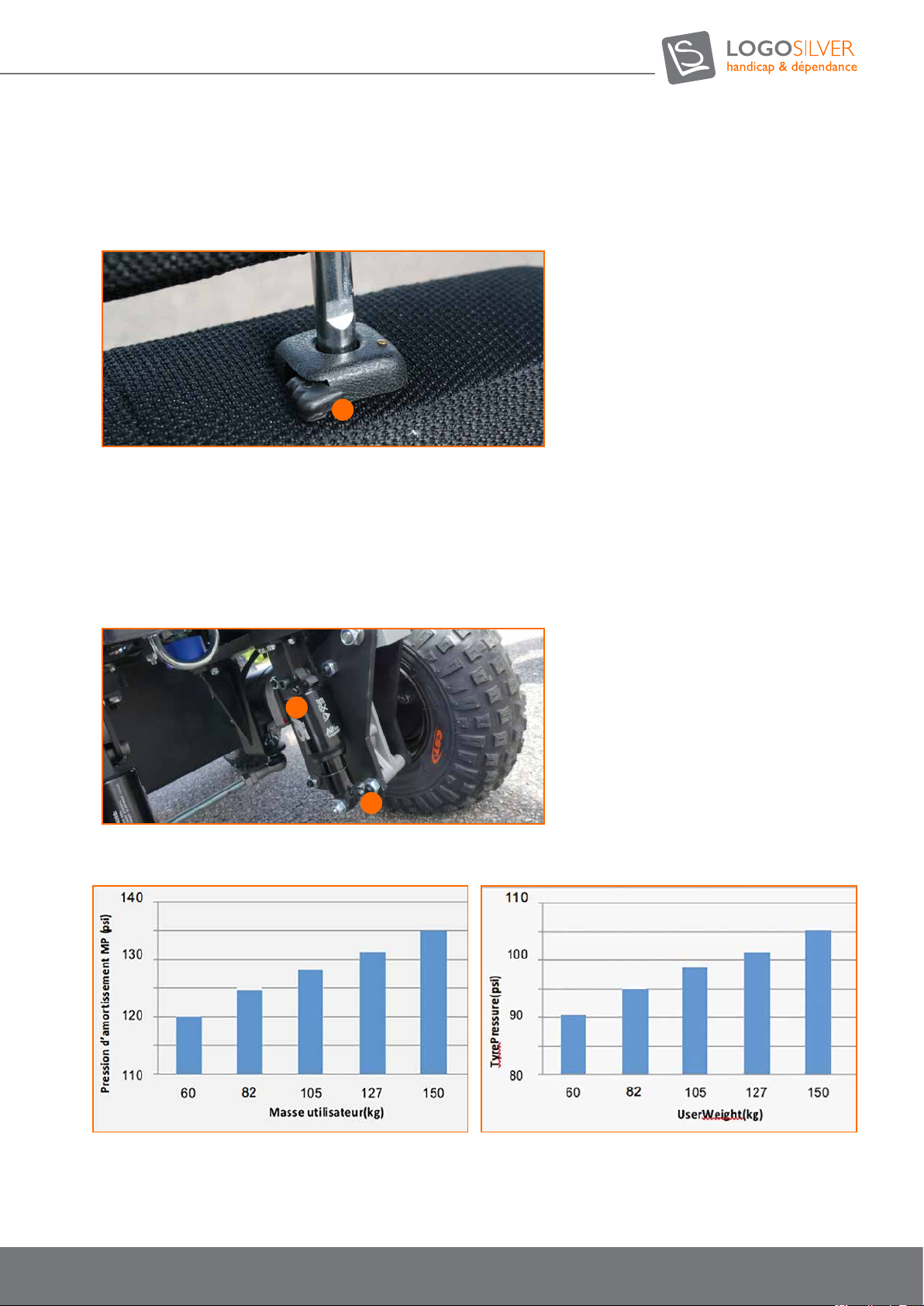
7.5.3.2. Headrest
19 - Headrest height
19
7.5.4. Shock absorber
The A5RR1 shock absorbers can be adjusted via two ATV type valves. The upper valve (MP) must be set to between 100
and 150 PSI (not to exceed 180 PSI), this is the main pressure damping that allows for adjustment of the depression of
the damper. The lower valve (NP) must be set between 65 and 100 PSI but must not exceed the main pressure, it is the
secondary pressure that manages the rebound damping. The pressure must be adjusted with a special damper pump. Do
not adjust the pressure of the shock absorber with a compressor at the risk of damaging it.
20 - Main MP pressure valve
21 - Secondary MP pressure valve
20
21
Recommended main pressure (MP) Secondary pressure (NP)
19
User manual OUTCHAIR
09/2018
Page 20
User manual
7.5.5. Tyre pressure
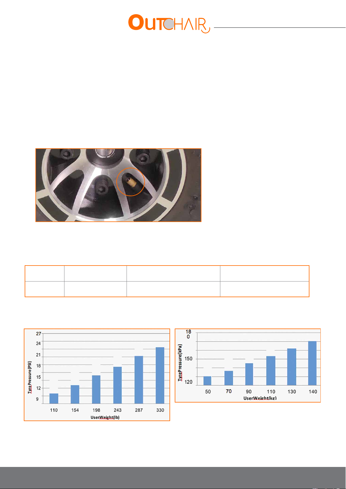
The tyre pressure needs to be adjusted according to the terrain. In off-road (bumpy ground, uneven surfaces, elds, path, mud,
sand, snow ...) it is recommended to adjust to a low pressure (between 0.4 and 0.5 bar), this will mean a greater comfort of use.
Less inated tyres provide better traction in mud, sand and snow.
To drive on rmer and smoother surfaces (asphalt), tyres can be inated to a maximum pressure of 1.6 bar depending on the
user’s weight, preferences and driving ability. The table below can help you adjust the pressure of your tyres on the asphalt. It is
recommended not to inate the tyres above 1.65 bar.
Tyre ination should be checked weekly. All tyres are equipped with automotive type valves and can be inated with most hand
or foot pumps, or with a compressor.
Warning: under-inated tyres can be dangerous and are more at risk of puncture. Poor ination pressure can affect chair
performance and pose risks.
Warning: over-inated tyres can burst and cause injury. The recommended pressure is also shown on the ank of the tyre.
Tyre Tyre Description Recommended off-road operating
pressure
All tyres Black, low pressure,
serrated
Recommended tyre pressure on asphalt depending on user
weight (Metric system)
5 psi (38 kPa)
MAX 7 psi (48 kPa)
Recommended tyre pressure on asphalt depending on user
weight (Imperial system)
Maximum tyre pressure according
to their capacity
24 psi
165 kPa
20
Page 21
7.5.6. Seat angle
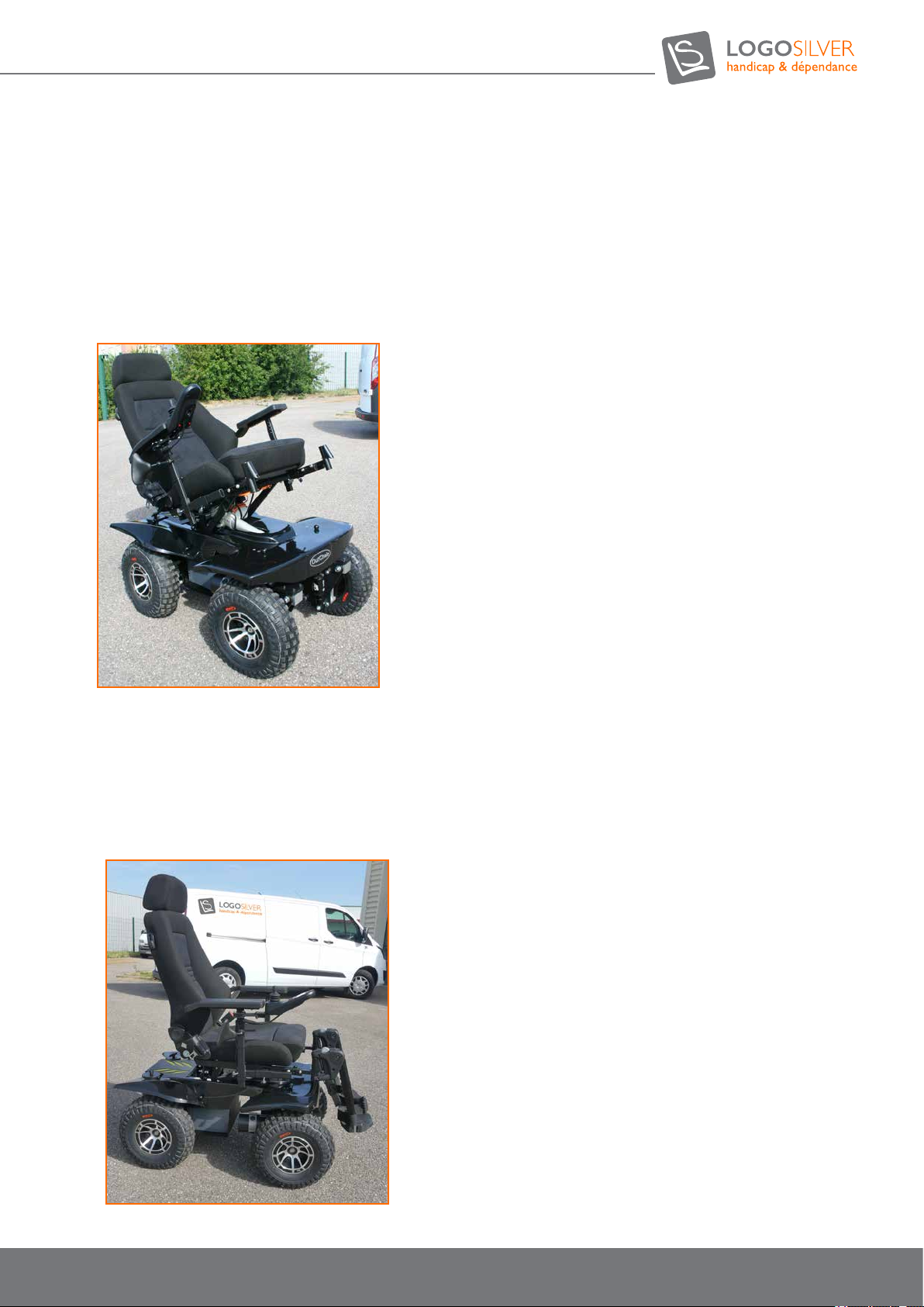
• The chair is equipped with a seat tilt that allows the user to relax the support points (avoiding the occurrence of pressure
sores) and have more comfort to rest.
• You can access this setting in the MODE menu by choosing «Seat inclination» when scrolling through the options to the
right or left using the joystick. Rear adjustment is done by pulling the joystick towards you and pushing it forward.
• Depending on the terrain, be careful not to be angled too far forward or backward. There is a risk of tipping the
wheelchair over, follow the recommendations for normal driving seat position.
7.5.7. Normal seat position when driving
• For normal use on the at, uphill and over obstacles, position the seat as parallel to the ground as possible with the
backrest as perpendicular to the ground as possible. When going downhill, you must tilt the seat 10 ° backwards from the
ground and the backrest 20 ° backwards from the vertical. These settings are specied to prevent the user from tipping
the chair over which could cause injury.
• These settings should not prevent the user from paying attention when shifting to certain user position limits. See also
Part 2. Security.
21
User manual OUTCHAIR
09/2018
Page 22
User manual
7.5.8. Joystick positions
• The joystick is mounted on a pantograph that can be folded backwards and to the side of the armrest to position it near
a table, for example.
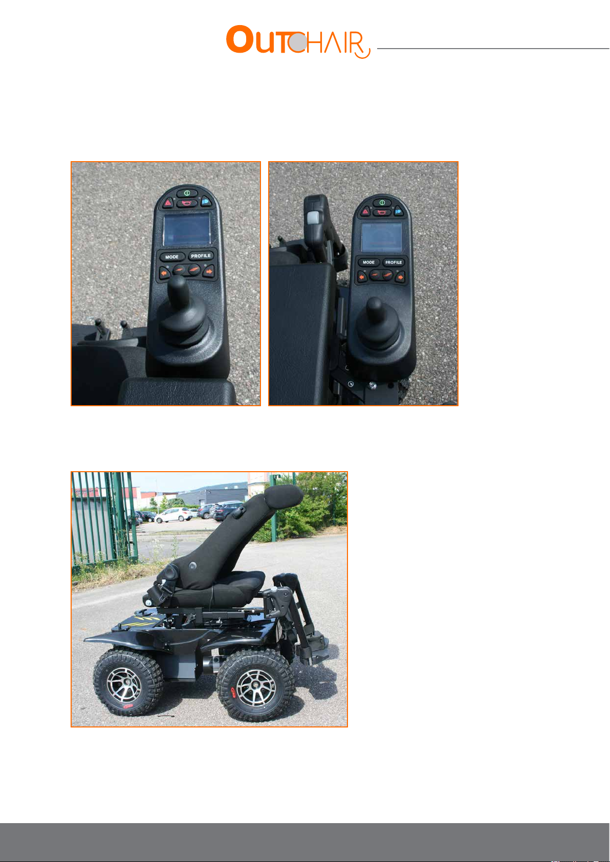
7.5.9. Folding the Recaro backrest (optional)
• The RECARO seat handles, when pushed upward, fold the seat forward to gain 15 to 20 cm in height for transport in a
vehicle.
22
Page 23
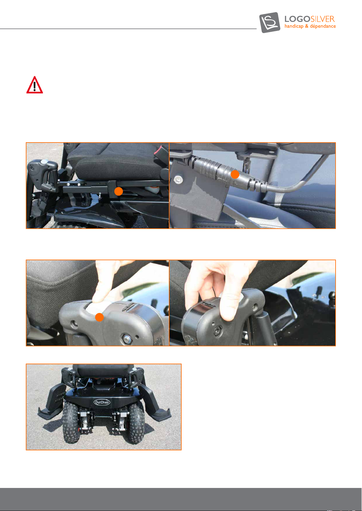
7.6. Transfer into the Chair
Danger
Switch off the joystick (lights off), and make sure that the engine brakes are engaged.
The retractable armrests of the chair allow for lateral transfer.
To do this, unscrew the armrest height adjustment knob (16) in order to remove it. If you make the transfer on the joystick side,
consider unhooking the joystick cable (17) before removing the armrest.
23
22
Retractable leg rests allow for a front transfer.
To do this, you need to remove the leg rests by pressing on the button (18), this unlocks the leg rests to the sides. Once the leg
rest is unlocked to the side it is detached by lifting it up.
24
You can also transfer from the front of the chair by shifting the leg rests to the sides.
After a few attempts, the user will be able to transfer from his chair into the Out Chair and vice versa in complete autonomy.
23
User manual OUTCHAIR
09/2018
Page 24
User manual
7.7. Switching on and off
Danger
Danger of death in case of malfunction of the engine brakes. When using the Out Chair the engine brakes must be engaged and in
working order.
7.7.1. Electronic system protection
The chair’s electronic control system is equipped with a current control device to prevent circuit damage in the event of
overload.
When the motors are subjected to considerable effort for a prolonged period, the power supplied by the device is
gradually reduced to prevent overheating.
This decrease in power can continue until the complete standstill of the chair. This phenomenon occurs more quickly when
the ambient temperature is raised.
Stopping for several minutes may then be necessary in order to return to maximum power.
When driving is blocked by an impassable obstacle and the user continues forward, forcing the engines to stall for more
than 10 seconds, the electronic system automatically turns off the power.
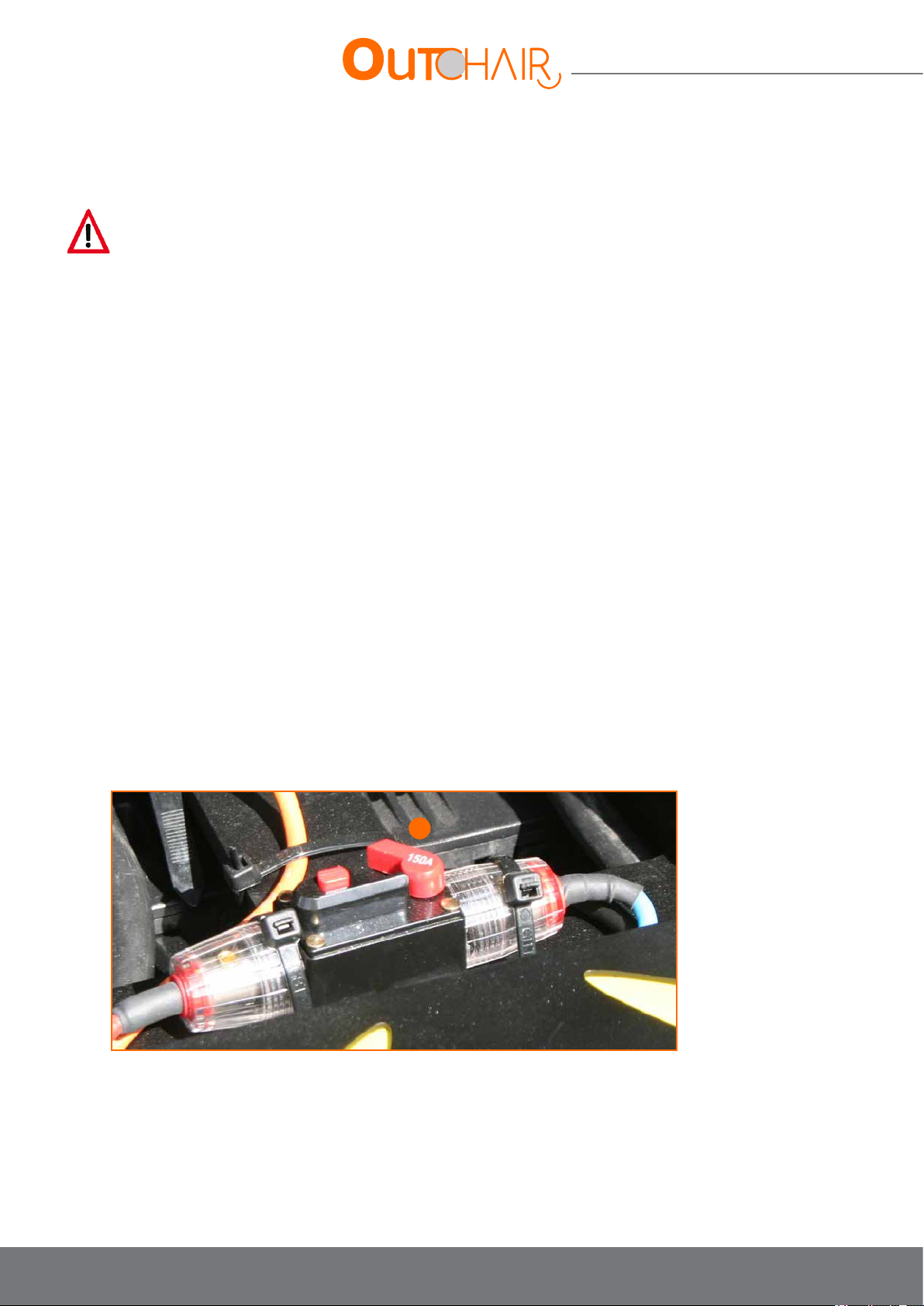
7.7.2. Circuit Breaker fuse box
In addition to the protection described in the previous paragraph, the entyre wheelchair electrical system is protected
against overload by a circuit breaker fuse located behind the seat.
The circuit breaker shouldn’t blow during normal operation. However, this can happen in the case of a low battery and an
excessive load.
The circuit can be cut via the red button on the circuit breaker. This action cuts power to the controller and other
electrical devices. It also prevents the batteries recharging.
Do not reset the circuit breaker several times in succession because if a problem persists this could damage the electronic
systems.
Do not reset the circuit breaker until there has been a complete inspection of the entyre electrical system (see paragraph
V Battery replacement). If the problem persists, contact us or a distributor.
25
Switch on the circuit breaker (armed) by pressing button 25.
7.7.3. Switching on
• The electronic system will turn on if:
• The circuit breaker is armed
• The joystick is on
• The electromagnetic brakes must be engaged otherwise the wheelchair will not move
24
Page 25
7.7.4. Switching off
• Turn off the joystick
• Check that the brakes are engaged so that the wheelchair does not move
• Be careful not to leave the chair at a standstill with empty batteries as this could affect its autonomy.
7.8. Joystick Control
The joystick controls can be personalized, and different models are available depending on the needs of the user.
7.8.1. Joystick
The joystick controls the speed and direction of the wheelchair. Push the joystick in the direction of your choice. The more
you incline it, the faster you will go. When you release the joystick, the chair will automatically brake and stop.
7.8.2. Powering the joystick
If the wheelchair does not move as intended, release the joystick immediately and turn off the chair. Unless the joystick is
damaged, the chair should stop.
If the joystick is not in the neutral (centered) position when you start the chair, you risk causing a system malfunction.
Release the joystick and restart the chair to reset the system.
WARNING
Always turn the chair off when at a standstill to avoid unexpected movement.
7.8.3. Rain and water
The joystick box is NOT WATERPROOF. The joystick module resists splashes but can be irreparably damaged if water
passes through the rubber seals (such damage is not covered by the warranty).
** We recommend carrying a plastic bag large enough to cover the joystick module and the user’s hand in case of rain.
7.8.4. Joystick cable
If, for any reason the joystick cable is disconnected, be careful not to force it back in again. The plug is polarized and can
only be inserted in one direction.
STOP
Do not insert the plug in the wrong direction, as this may cause irreparable damage to the electronic system. Also, be sure to place the
cable so that it cannot get caught in the seat frame or the base of the wheelchair.
7.8.5. The control programme
The control programme affects the speed, acceleration, deceleration, and braking of the chair. The drive mode settings are
pre-programmed at the factory. If your Magic Mobility dealer changes these settings, please take note.
WARNING
Do not try to reprogram your chair yourself. This task must only be carried out by the wheelchair manufacturer, an authorized
representative of the manufacturer or a qualied technician.
25
User manual OUTCHAIR
09/2018
Page 26
User manual
7.8.6. Precautions for use
The R-net cannot take into account circumstances that place the chair or controller beyond the specied operating
conditions, and it is therefore important that the user takes the following precautions:
Do not drive the chair:
• beyond the restrictions specied in the chair manual, for example regarding the maximum inclination, the maximum height
of the sidewalk, etc.
• on surfaces where loss of adhesion could be dangerous, for example on a wet grass slope.
• it is known that the controller or another essential component needs to be repaired.
WARNING
Logo-Silver assumes no liability for any type of damage resulting from the unforeseen breakdown of the wheelchair or bad programming
of the control system, improper use of the wheelchair or control system, or if one of the criteria detailed in this document has not been
respected.
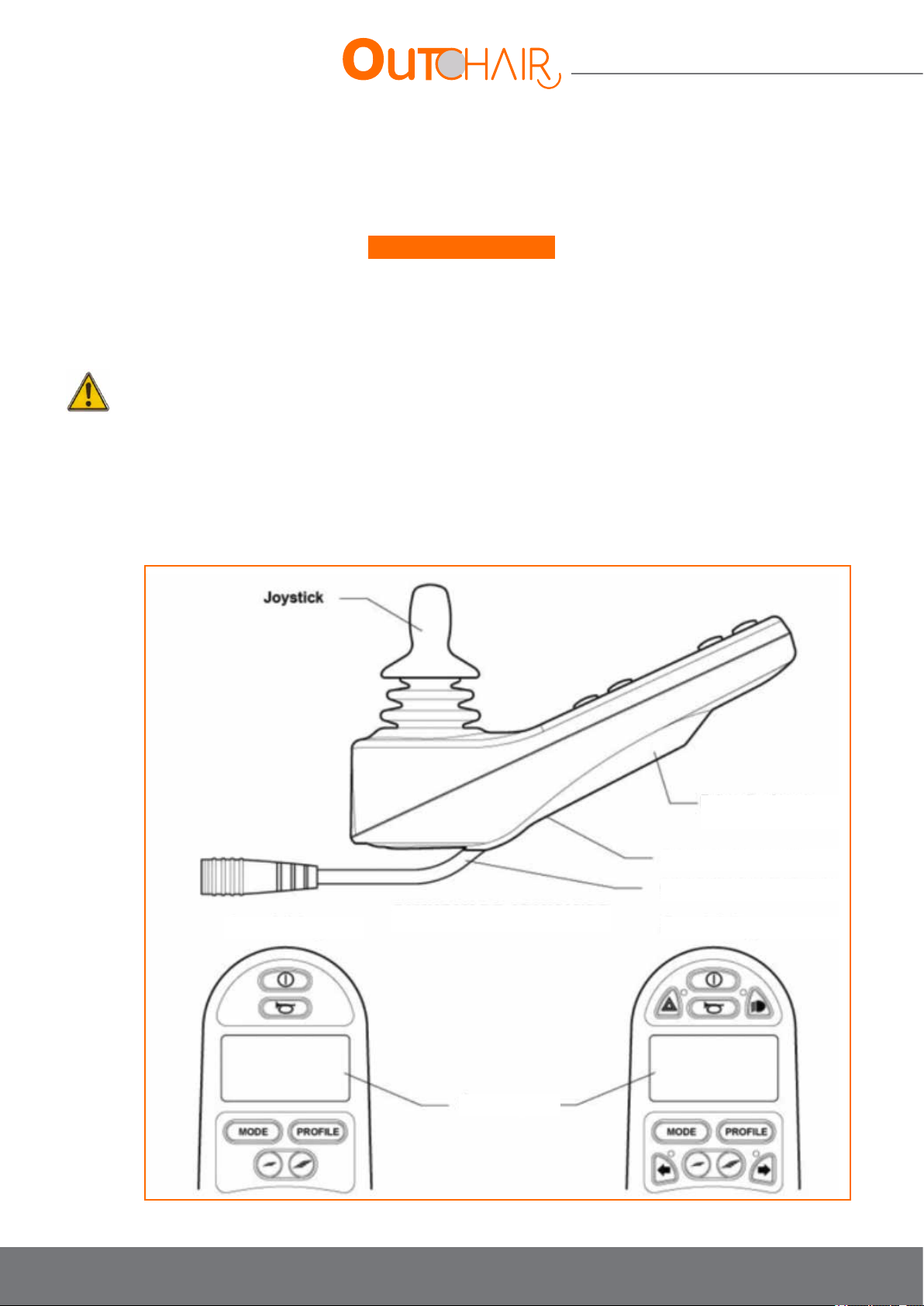
7.8.7. LCD Joystick
7.8.7.1. Control panel
Without lighting With lighting
Charger socket
External switch jacks
Communication cable
CONTROL PANEL
LCD screen
26
Page 27
• Power button: This button turns the R-net control system on and off. Do not use this button to stop the
chair, except in case of emergency.
•
Horn Button: This button activates the wheelchair horn.
•
The Mode button allows the user to browse through the operating modes available in the control system.
•
The Prole button allows the user to browse the operating proles available in the control system.
•
Reduce Speed button - reduces the maximum speed setting. Increase Speed button - increases the
maximum speed setting.
•
This button turns the headlights on and off. The LED will illuminate when the headlights are on.
•
This button turns the hazard lights on and off. The LED will ash when the hazard lights are on.
•
This button turns the left indicators of the chair on and off. The LED will ash when the left indicators are
on. This button turns the right indicators of the chair on and off. The LED will ash when the right indicators
are on.
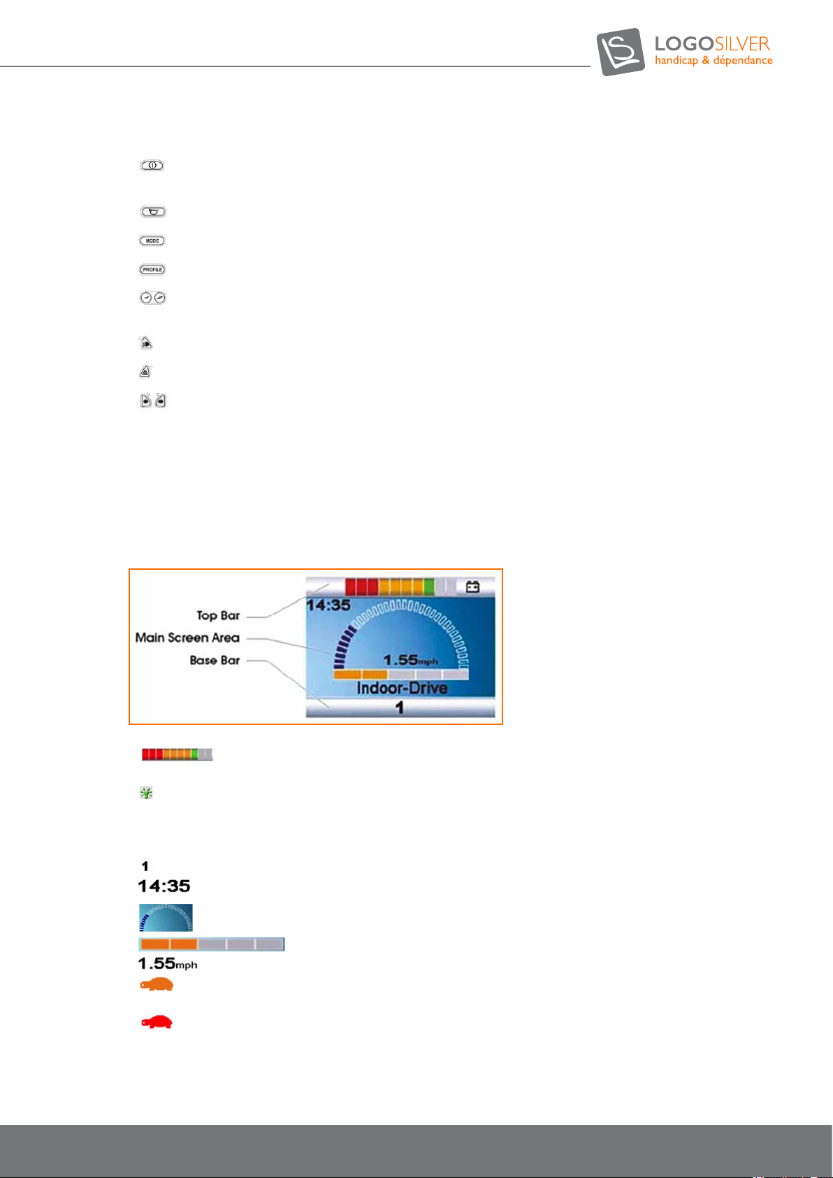
7.8.7.2. LCD screen control system Indicators
The colored LCD screen is divided into three information zones:
1 - Top Bar
•
Battery Indicator: Displays the available charge on the battery and indicates the status of the
battery. See «Batteries and Charging» for more information.
• Lightbulb Symbol: When multiple controllers are installed, the one that currently controls your chair displays
this symbol.
2 - Base bar
• Current prole: The selected prole is displayed in digital fo
• Clock: Displays the current time in digital format. The clock is adjustable by the user. See the Settings
Menu section (below) for more details.
• Speed Display: Gives a display proportional to the speed of the wheelchair.
• Maximum speed indicator: Displays the current maximum speed setting.
• Digital Speed Display: Displays the actual speed of your electric wheelchair.
• Inhibition: If the wheelchair speed is limited (for example, by a raised seat), this orange symbol will be
displayed.
• If the wheelchair drive is inhibited (for example, using the transfer tilt), this red symbol will ash.
27
User manual OUTCHAIR
09/2018
Page 28
User manual
3 - Barre de base
• Prole name: Displays the prole name selected.
• Engine Temperature: This symbol means your control system has reduced engine power to protect against
heat damage.
• Control System Temperature: This symbol means your control system has reduced its own power to protect
against heat damage.
Mode screens:
•
• Bluetooth mode: When Bluetooth mode is enabled, the following screen is displayed.
• Message Window: The R-net Control System displays warning icons and informational
messages in an allocated message window.
• Restart: When the control system requires a restart, this symbol ashes..
• Timer: This symbol appears when the control system is moving from one state to another.
• Standby: This symbol will be displayed for a short time before the R-net goes on standby.
• Checkmark: Process performed correctly (check mark).
• Cross: Process not performed correctly (cross mark).
• E-stop : E-stop: If you have an external prole switch and you turn it on while operating your chair or an
actuator, the action will stop, and this symbol will be displayed.
• Displaced joystick: If you manipulate the joystick before or just after turning on the control system, the
displaced joystick icon will ash on the screen. If you do not return the joystick to the central position within
ve seconds, your chair will not move. Turn off the control system and turn it back on to reset it.
• Locked control system: The control system can be locked using a sequence of joystick movements or
with a physical key. See «Locking the Control System» for a detailed description of the locking and unlocking
procedures.
Action Mode: Displays the sections of the chair selected for movement.
• Diagnostics Screen: When the safety circuit begins preventing wheelchair movement, the diagnostic
screen is displayed.
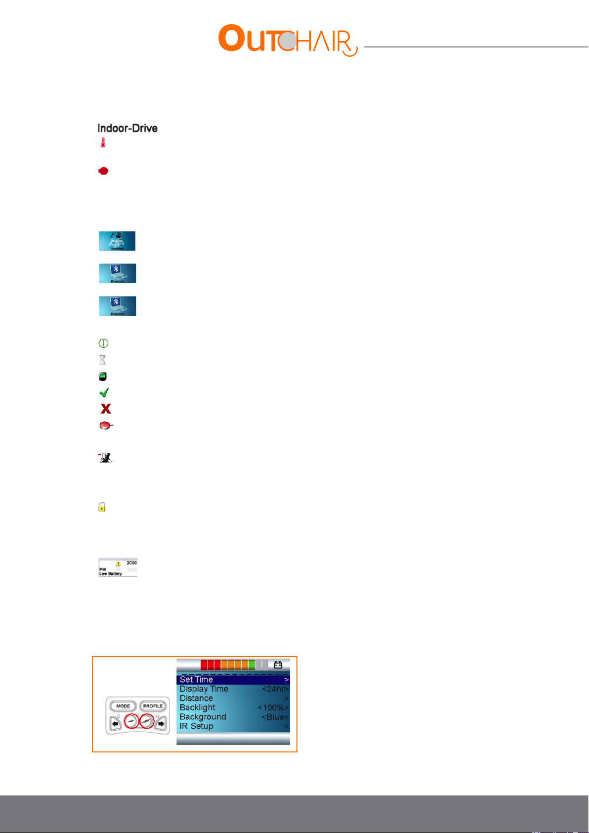
7.8.7.3. Basic programming and conguration
• Basic programming can be performed by simultaneously pressing and holding the increase / decrease buttons.
This will take you to the Settings menu :
28
Page 29

Adjusting the time:
• Shift the joystick once to the right to open the clock settings. Set the time using the joystick.
• Display format: the options given are 12 hours, 24 hours or turned off. Shift the joystick to the left or right to
scroll through the options.
Distance:
• Total distance: Displays the total distance travelled in your current power module.
• Journey distance: Displays the total distance travelled since the last reset.
• Distance display: Denes whether the total distance or the distance of the journey must appear on the
odometer.
• Clear journey distance: Shift the joystick to the right to clear (reset) the distance value of the trip.
• Exit: Shift the joystick to the right to return to the Settings men
• Backlighting: Sets the backlight intensity of the LCD screen. The adjustment range is from 0% to 100% in
increments of 10%. The adjustment is made by shifting the joystick to the left or to the right.
• Background: Sets the colour of the wallpaper. Shift the joystick to the left or right to scroll through the options.
Choose «Blue» or «White» to display the background colour specied in all proles. Choose «Auto» for a
background that will be blue for slower indoor modes and white for faster outdoor modes.
• Exit: Exit the Settings menu to return to normal operation.
29
User manual OUTCHAIR
09/2018
Page 30
User manual
7.8.8. Joystick CJSM2-BT (optional)
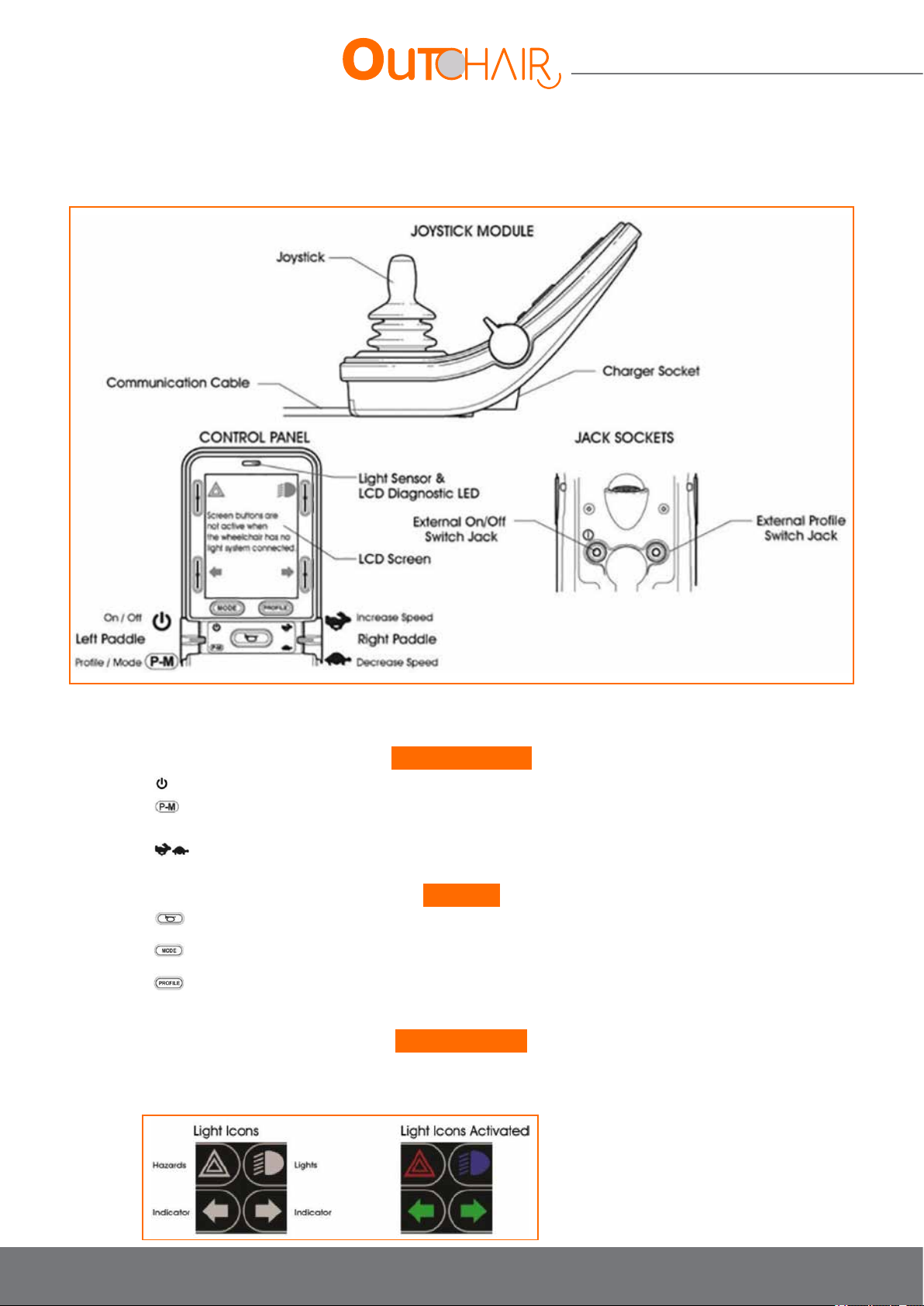
7.8.8.1. Control system information
Paddle Switches:
•
On / Off control: Activated by pushing the left switch forward.
• Prole / Mode control: selects available driving proles and operating modes by pulling the left switch
backward.
• Speed Control: Sets the system speed setting.
Buttons:
•
Horn Button: This button activates the wheelchair hornt.
•
The Mode button allows the user to browse through the operating modes available in the control system.
•
The Prole button allows the user to browse the operating proles available in the control system.
Screen buttons:
These buttons operate the lighting functions: Danger, lights, left indicator and right indicator. The function of each
button is illustrated by the icon displayed next to each button on the screen.
30
Page 31
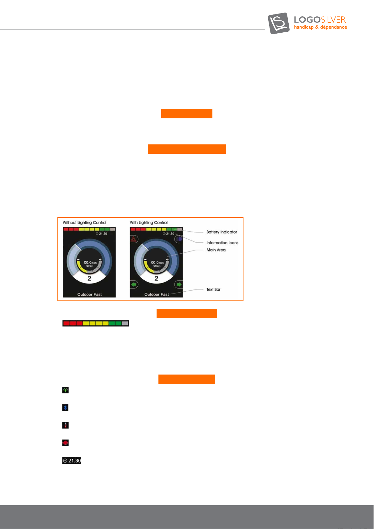
Pressing the corresponding key activates and deactivates the function. Once the function is activated, the icon on
the screen will light up or ash, depending on the function.
If no lighting system is available on the chair, these buttons will remain inactive.
The upper left button opens the settings menu when held down for a few moments.
Light detector:
The controller has an ambient light sensor that automatically adjusts the brightness of the screen.
For options, refer to the basic programming and conguration.
LED screen diagnostics:
This LED light indicates that the control system is operating normally. In the event of an LCD screen fault, turn off
and then turn on the control system. If the problem persists, contact your LogoSilver dealer.
7.8.8.2. Indications on the control system screen
The state of the control system is indicated by the LCD screen, divided into 4 information zones:
Battery indicator:
•
Battery Indicator: Displays the available battery charge and indicates the status of
the battery
- Fixed: Everything is running ok.
- Slow blinking: Charge the battery as soon as possible.
- Incrementing: The wheelchair batteries are loading.
Information bar:
•
Lightbulb Symbol: When multiple controllers are installed, the one currently controlling your chair displays
this symbol.
• Bluetooth: This symbol appears when a Bluetooth module is connected to the system. The symbol is blue
when connected with a Bluetooth device and blank when not connected.
• Engine Temperature: This symbol means your control system has reduced engine power to protect against
heat damage.
• Control System Temperature: This symbol means your control system has reduced its own power to protect
against heat damage.
• Clock: Displays the current time in digital format. The clock is user adjustable.
31
User manual OUTCHAIR
09/2018
Page 32
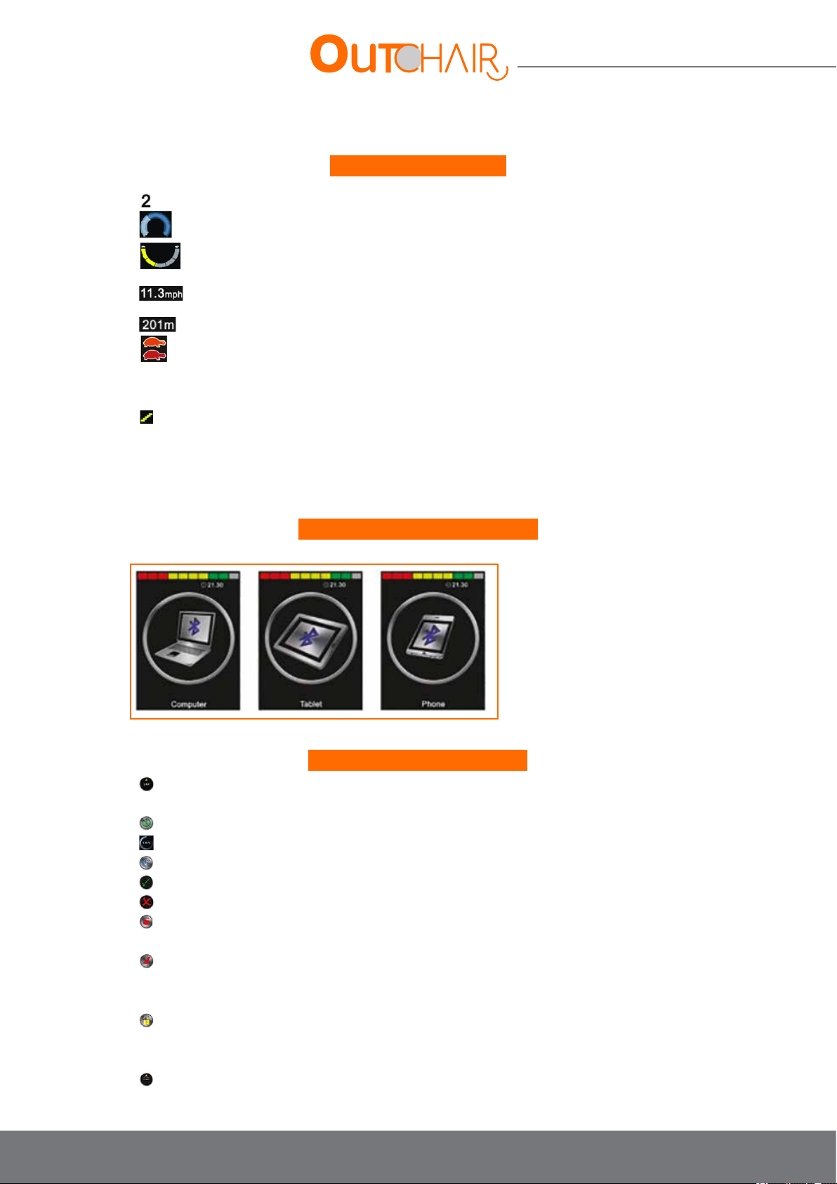
User manual
Current prole: The selected prole is displayed in digital format.
•
• Speed display: Gives a display proportional to the speed of the wheelchair.
• Maximum speed indicator: Displays the current maximum speed setting.
• Digital Speed Display: Displays the actual speed of your electric wheelchair.
• Odometer: Displays the total distance travelled by the chair, or the distance travelled since the last reset.
• Inhibition: If the chair speed is limited (for example, by an elevated seat), the orange symbol will be
displayed. If the wheelchair drive is inhibited (for example, when using the transfer tilt), the symbol will ash red.
• Lock: This symbol appears if the control system is lock.
• Seat settings screen: Displays the part of the chair selected for adjustment, and a direction arrow.
Move the joystick to the left or right to select the desired adjustment axis.
Move the joystick forwards or backwards to move the seat
Main area, drive screen:
Bluetooth mode setting screens:
• Bluetooth mode: When Bluetooth mode is enabled, one of the following screens appears
General information symbols:
•
Limp: This message is displayed if a user switch has been disconnected and the control system is
programmed to continue to allow slow speed operation.
• Restart: When the control system requires a restart, this symbol ashes.
• Timer: This symbol appears when the control system is moving from one state to another.
• Standby: This symbol will be displayed for a short time before the R-net goes to sleep.
• Process performed correctly.
• Process performed incorrectly.
• E-stop (emergency stop): If you have an external prole switch and turn it on while operating your chair or
an actuator, the action will stop and this symbol will be displayed.
• Displaced joystick: If you move the joystick before or just after turning on the control system, the displaced
joystick icon will ash on the screen. If you do not return the joystick to the central position within ve
seconds, your chair will not move. Turn off the control system and turn it back on to reset it.
• Locked control system: The control system can be locked using a sequence of joystick movements or with a
physical key.
• See «Locking the Control System» for a detailed description of locking and unlocking procedures.
• Diagnostics: When the safety circuit begins preventing wheelchair movement, the diagnostic screen is
displayed.
32
Page 33
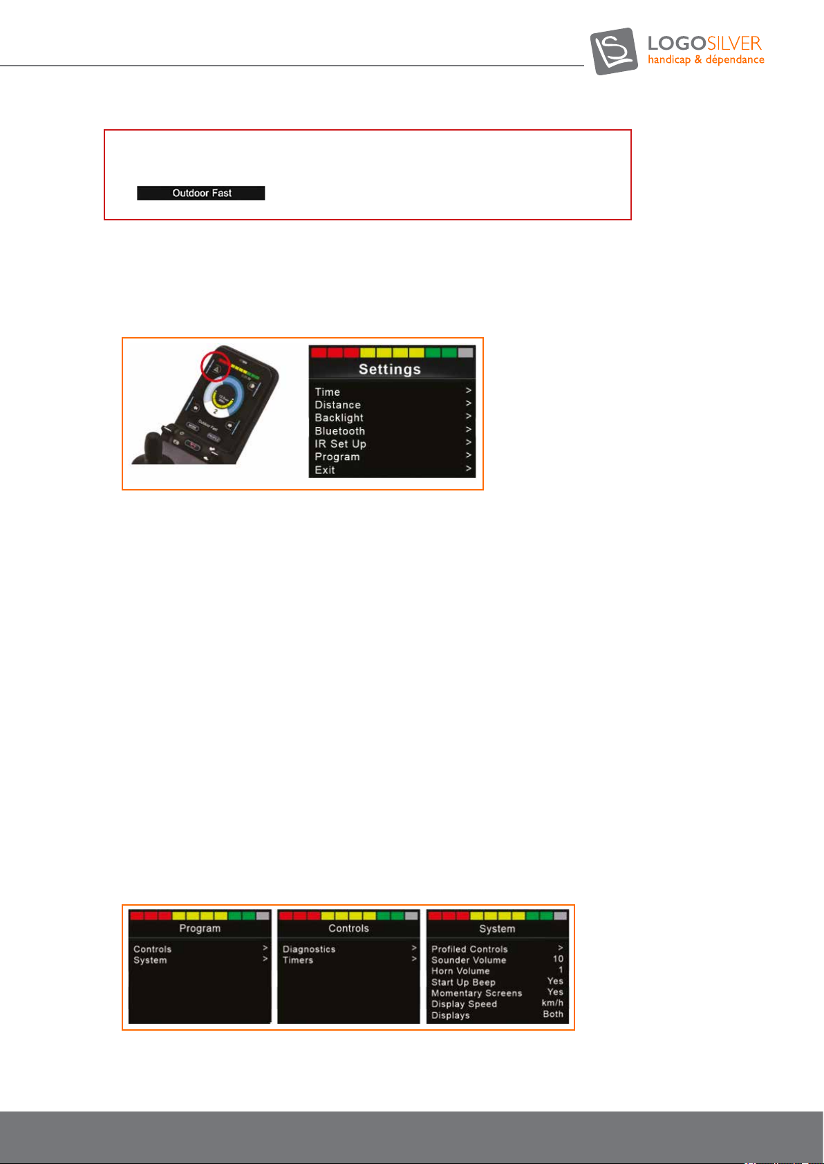
Text Bar
•
Nom du prol : Afche le nom du prol sélectionné.
7.8.8.3. Basic programming and setup
• Press and hold the button in the upper left corner of the screen (Danger button) for 1 second.
This action will display the menu:
• Setting the time: shift the joystick once to the right to open the clock setting. Set the time using the joystick.
• Display format: Options are 12 hours, 24 hours or turned off. Shift the joystick to the left or right to scroll
through the options.
• Total distance: Displays the total distance travelled with your current power module.
• Distance of the trip: Displays the total distance travelled since the last reset.
• Distance display: Denes whether the total distance or the distance of the trip must appear on the odometer.
• Clear journey distance: Shift the joystick to the right to clear (reset) the distance value of the trip.
• Exit: Shift the joystick to the right to return to the Settings menu.
• Backlighting: Sets the backlight intensity of the LCD screen. The adjustment range is from 0% to 100% in
increments of 10%. The adjustment is made by shifting the joystick to the left or to the right.
• Automatic backlight: The controller has an ambient light sensor. When activated, the screen adjusts its brightness
according to the external brightness:
• Exit: Exit the Settings menu to return to normal operation.
33
User manual OUTCHAIR
09/2018
Page 34

User manual
7.8.8.4. Pairing the CJSM-BT
Enter the «CJSM2 Setup» menu and select «Bluetooth». The names of the preprogrammed devices should appear.
Logo-Silver has preprogrammed the following devices:
• iPad
• iPhone
• PC
• Android device
Press and hold the top left screen button (Danger button) for 1 second to enter the settings menu.
To start the pairing process, turn on the device by pushing the joystick to the right.
After turning on the device, turn on the controller
Select the item you wish to pair by scrolling through the drop-down menu, and select the device by pushing the
joystick to the right.
7.8.8.5. “Discovery” mode
Push the joystick forward for 10 seconds until it sounds, then pull it back until it sounds. There should now be a
blinking Bluetooth icon on the CJSM2 screen. This means that the CJSM2 is detectable.
Select the device (e.g. Tom’s iPad) to connect and search for Bluetooth devices; this launches the connection to
the R-net. Once connected, «Tom’s iPad» will appear in the Connected Devices window and you will be able to
navigate from the iPad using the CJSM2-BT from the R-net.
To connect to an additional device (e.g. Tom’s PC), select the device and repeat the process above. Up to four
devices can be connected.
Selection of different connected devices:
Once the devices are paired, they will stay connected to the R-net. When entering the «My Devices» mode,
the last device connected will always be the option selected in the menu. To select another device, scroll to the
desired device and push the joystick to the left or right. After a few seconds, a xed Bluetooth icon will appear on
the CJSM2 screen, and navigation from the new device will begin.
Disabling connected devices:
To turn off a connected device and delete it from the menu displayed in «My devices», select «Bluetooth» in the
settings menu. The devices can be disabled by pushing the joystick to the right.
Note: It is not necessary to pair the device again if it is turned on at a later stage.
34
Page 35
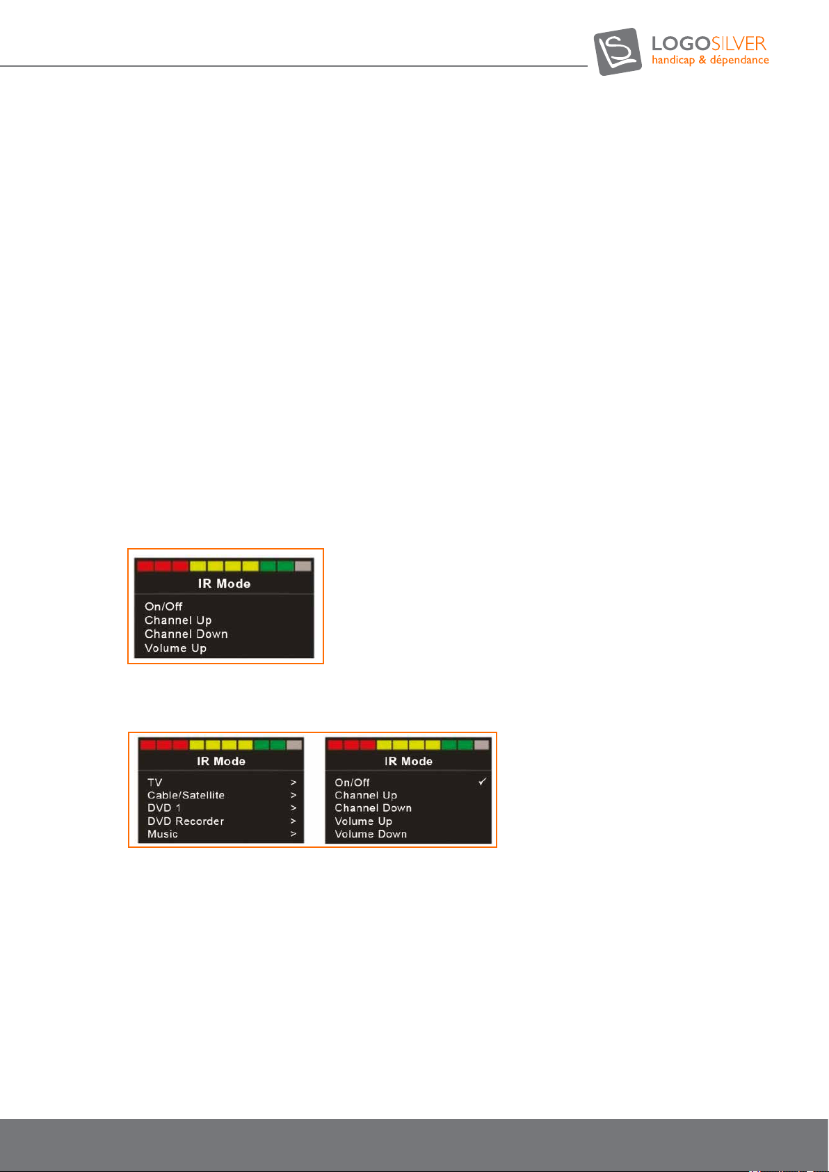
7.8.8.6. Control through infrared (IR)
The CJSM2-BT includes an infrared transceiver that replicates most common infrared remotes. (Note: The
CJSM2-BT is not compatible with all infrared devices.)
These devices include:
Televisions, audio-visual systems, electric curtains, DVD players, soundbars, media managers, VCRs, Blu-ray, auxiliary
devices, set tops, projectors, door opening mechanisms, CD players, receivers / preampliers, air conditioning
systems, home theatre systems, switches, lighting...
If you have questions about a particular device, make sure you provide the make, type and model of device.
Example: Panasonic, Home theatre set, SA-BT set with Blu-ray...
IR mode:
The «IR Mode” is accessible by selecting Mode on the menu. This mode will only be available if the IR codes have
been saved in the CJSM2-BT.
Once you are in IR mode, a list of IR devices is displayed along with the IR commands associated with each device.
In the case of a TV, for example, commands such as these would be available: On / Off, Channel Up, Channel
Down, Volume Up, and Volume Down. When the CJSM2-BT transmits the selected command, it is highlighted with
a red background.
IR Setup (IR conguration):
The «IR Setup» menu is accessible from the «Settings Menu». When you enter the «IR Setup» menu, the default
devices are displayed. Select a device to display its commands.
If a command is checkmarked, it means that an IR code has been stored. If there is no checkmark, no IR code has
been saved for this command.
35
User manual OUTCHAIR
09/2018
Page 36

User manual
To learn the CJSM2-BT an IR code, access the «IR Setup» menu and select a device.
• Select the command to be learned (for example: TV> Channel Up)
• Select «Learn Code» using the right button while the command is highlighted.
• Point the TV remote at the LED CJSM2-BT Receiver and press the «Channel Up» button on the TV remote
control twice. You will hear a «beep» after each press. After the rst press, the «2x» on the LCD is changed to
«1x» which will then ask you to conrm the code by pressing the «Channel Up» button once again.
•
A checkmark indicates that the instruction has been successful.
Learning the IR codes:
•
A cross indicates a failure, in this case, repeat the procedure.
• Once the code is learned, select “Exit” to return to the TV control menu.
• There is now a checkmark next to the newly learned command, since an IR code is now stored for this
command.
Note: The rst time an infrared code has been learned, switch off then on the CJSM2-BT and make sure it is
working properly.
Learning the IR code sequence:
Saving an IR code sequence allows you to execute multiple IR commands with a single command from your
CJSM2-BT, such as turning on both a DVD player and a TV.
To save a sequence:
• Select the command used to begin the sequence. Take for example, use TV> On / Off to begin the sequence.
• Select «Learn Code» using the right button while the command is highlighted.
• Point the television remote control at the LED CJSM2-BT receiver and press the «On / Off» button on the TV
remote control twice.
• After each successful instruction, a checkmark appears momentarily on the screen, select «Learn Code» once
more.
• Point the television remote control at the CJSM2-BT Receiver LED and press the «On / Off» button twice.
• After each successful instruction, a check mark appears momentarily on the screen, select «Learn Code» to add
a new code to the sequence or «Exit» if the sequence is complete.
Now, the On / Off command has a checkmark followed by 3 dots to indicate that a sequence has been learned.
36
Page 37
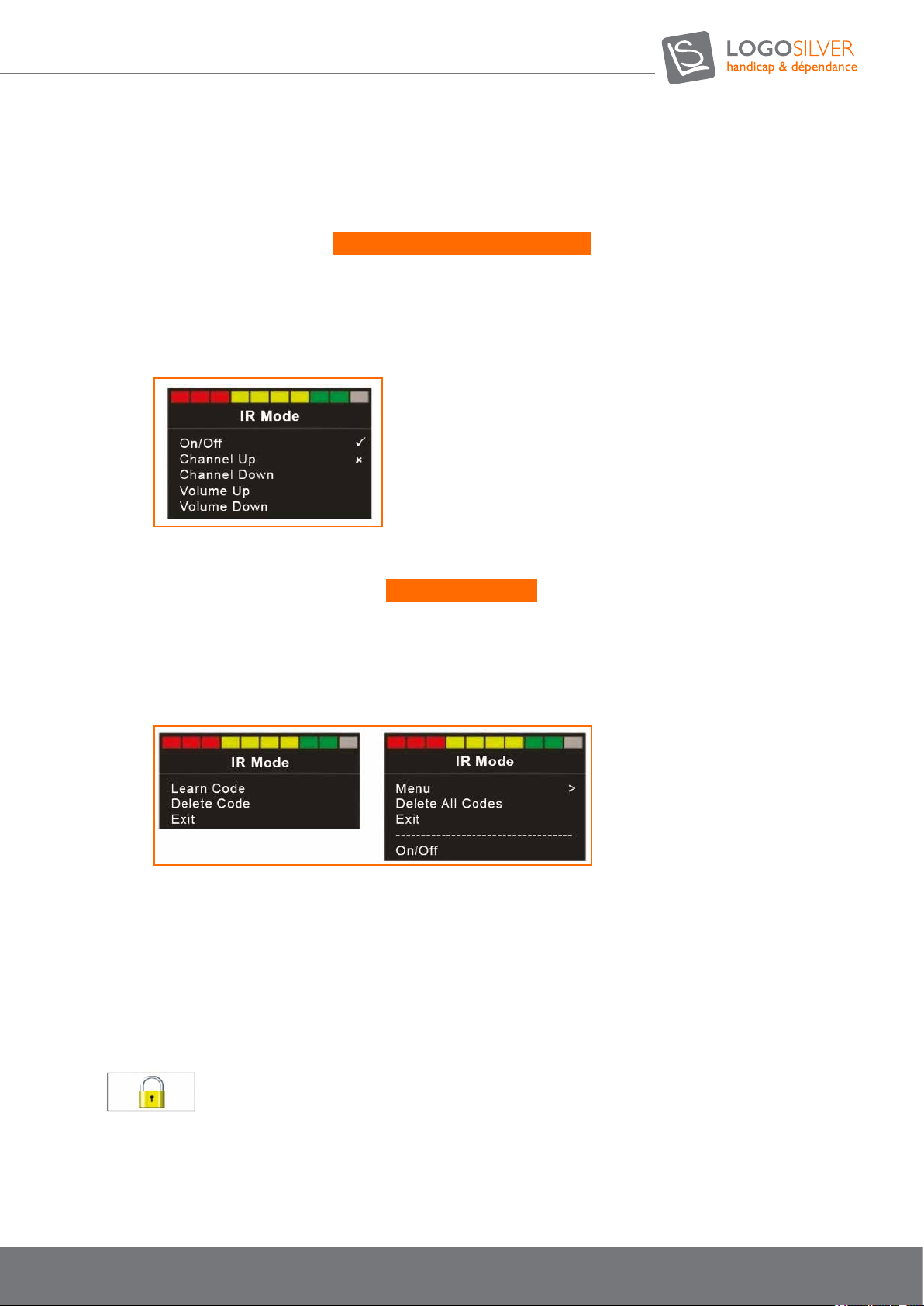
• Use the same process to teach multi-digit channels. You can choose to store specic channels instead of
numbers in your «Channel Selection» menu.
Enabling and disabling IR codes:
IR codes can be enabled or disabled using the «IR Set Up» menu.
• To deactivate an IR code, select the - key on the front panel of the CJSM2-BT. Deactivated IR codes are displayed with
an X next to the highlighted command.
• To activate an IR code, select the + key on the front panel of the CJSM2-BT. Active IR codes are displayed with a
check mark next to the highlighted command.
Deleting IR codes:
• To remove the infrared code from a command, highlight the specic command in the device menu and press the
right button. Then select the «Delete code» option (Figure 23).
• To delete all IR codes from a device, select «Delete All Codes». Then switch off then on the CJSM2-BT to make
sure it is working properly.
•
7.8.9. Locking the control system
The control system can be locked using a sequence of buttons on the numeric keypad or with a physical key. This will be
set at the factory.
• Keypad lock: When the control system is activated, hold the On / Off button down.
• After one second, the control system will beep. Release On / Off button.
• Shift the joystick forward until the control system emits a beep.
• Shift the joystick backwards until the control system emits a beep. Release the joystick, a long beep will sound.
• The wheelchair is now locked.
•
The following screen will be displayed next time the control system is started up.
• To unlock the wheelchair: If the control system is off, press the On / Off button.
• Shift the joystick forward until the control system emits a beep. Shift the joystick back until the control system emits a
beep. Release the joystick, a long beep will sound.
• The chair is now unlocked.
37
User manual OUTCHAIR
09/2018
Page 38
User manual
Locking with the key: Once the control system has been turned on, insert and remove the supplied PGDT key from the
charger jack on the joystick module. A short beep will sound. The wheelchair is now locked.
•
To unlock the wheelchair: If the control system is off, press the On / Off button.
• Insert and remove the supplied PGDT key from the charger jack on the joystick module.
• A short beep will sound.
• The wheelchair is now unlocked.
7.8.10. Screen
• Avoid hitting the control system, especially the joystick.
• When transporting your wheelchair, make sure that the control system is well protected.
• To prolong the life of the control system, avoid exposing it to extreme conditions as much as possible. Always clean your
control system if it gets contaminated with food or drink.
• To clean it, use a damp cloth and dishwashing liquid diluted in water. Do not use abrasive or alcohol-based cleaning agents.
7.9. Driving Tips
Warning
We recommend that the user wear light or reective clothing in the dark and / or activate the lighting of the Out Chair (optional)
Once the power has been turned on (§ 7.4), select the Off-road prole.
The following screen will be displayed next once the control system is started.
Warning
The proles must be activated at a standstill.
The Out Chair can be driven on climbs and descents of 10°. It is prohibited to climb or descend inclines higher than this
percentage. In order to guarantee a safe downhill descent, it is necessary to reduce speed depending on the gradient and to
avoid sudden braking. In order to guarantee a safe climb, reduce speed and do not accelerate too hard.
It is prohibited to cross over a height greater than 15 cm on the Out Chair. Obstacles must be cleared at reduced speed. If
obstacles greater than 15 cm obstruct the path, they must be bypassed. Ground that is too uneven could cause uncontrollable
driving. That’s why you must constantly adjust your speed.
Danger
It is prohibited to drive on a slope (transverse incline) greater than 5°.
7.10. Batteries and Recharging
7.10.1. Batteries
Your electric wheelchair uses long-lasting electrolyte gel batteries that are sealed and require no maintenance. There is
no need to check their electrolyte level. Despite being similar to car batteries, these are different. Car batteries are not
designed for long and deep discharge, and their use in electric chairs could be dangerous.
38
Page 39

Warning
The battery terminals and their accessories contain lead, wash your hands after handling them.
Warning
Batteries contain corrosive chemicals. Only use AGM or gelled electrolyte batteries to reduce the risk of leakage or volatile conditions.
Warning
When changing the batteries, make sure that their terminals do not touch the wheelchair frame.
STOP
Car batteries and chargers should not be used with an electric wheelchair..
7.10.2. Charging the batteries
We recommend only using a supplied, high quality battery charger with your electric wheelchair. Use only the external
charger provided or a Logo Silver approved charger. Do not use a car battery type charger.
Fully charge new batteries before use. Drive the electric wheelchair at home or on private property; do not go too far
until you get used to the commands. After this rst use, fully charge the batteries. After four or ve cycles, the batteries will
operate at their maximum potential.
The charger will not work if the batteries have been depleted at an extremely low voltage. If this happens, call your Logo
Silver dealer for help.
7.10.3. Breaking in the battery
It is especially important to take good care of the battery during the «break-in» period to optimize its lifespan.
Procedure:
• Make sure the battery is fully charged before its initial use;
• Use the chair as normal during the day, avoid carrying excessive loads during the rst ve cycles;
• Fully charge the chair at night, checking that the charger indicates that the battery is fully charged (switches to charge
maintenance mode);
• Repeat steps 2 and 3 the rst 20 times (cycles) to complete the «break-in» procedure.
Notes
A new battery will require more time to fully recharge, but the time required will decrease. Initially, you may nd that you have to limit
use during the day so that the battery is fully charged.
• The battery capacity is limited when it is new, this is perfectly normal, and this will improve during the breaking-in process.
39
User manual OUTCHAIR
09/2018
Page 40
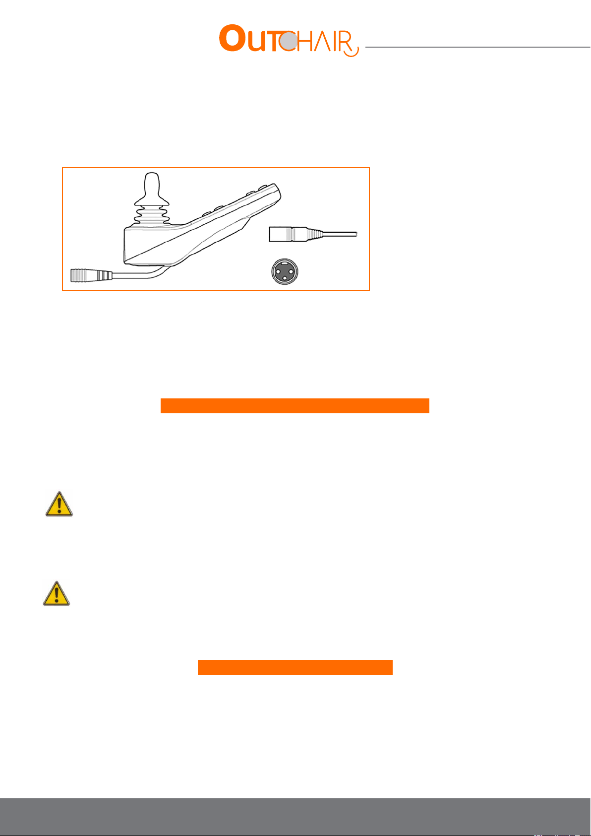
User manual
7.10.4. Charging procedure
The battery is charged via a socket located on the joystick module. When the charger is plugged in, the module recognizes
it and stops the chair from moving. The following procedure is applicable for the recommended charger brand (See
separate charger instructions if using an alternative charger).
1 . Make sure the chair is off using the on / off joystick button.
2 . Make sure the circuit breaker fuse is armed so as not to prevent the batteries recharging.
3 . Make sure the charger is turned off before plugging it into the chair.
4 . Plug the charger into the jack on the joystick module.
5 . Connect the charger to the 220 V mains.
6 . Please refer to the manual supplied with your charger for detailed instructions.
Here are some tips for taking care of your batteries:
• Avoid ultra-deep discharges (total discharges reduce the life cycle)
• Do not leave batteries on a low charge for a long period (for example, after a day of use,
• Completely recharge the batteries during the night),
• Once the batteries are empty, recharge them completely (this may take more than eight hours).
Warning
Always protect the batteries from freezing and never try to charge a frozen battery. You could hurt yourself and damage the battery.
Avoid the risk of electric shock. Protect the charger from moisture and extreme temperatures. Do not use the charger if it has been
dropped or damaged. Only use extension cords in good condition.
STOP
Do not place the charger on the chair seat during recharging, as it may become very hot. Always place the charger on the oor or near
the chair when in use. Avoid placing the charger near a heat source such as a radiator or exposing it directly to sunlight.
To optimize the life of your batteries:
• Fully charge the batteries before moving around
• Make sure tyre pressure is correct for the weight and surface
• Avoid stopping too frequently; try to keep a constant speed
• Try to avoid inclines
• Limit the weight of onboard luggage
• Do not operate the control system if the battery is almost empty. Failure to do so may leave the user immobilized in a
dangerous position, such as in the middle of a road. Magic Mobility claims no responsibility for losses of any kind resulting
from a failure to follow these instructions.
40
Page 41
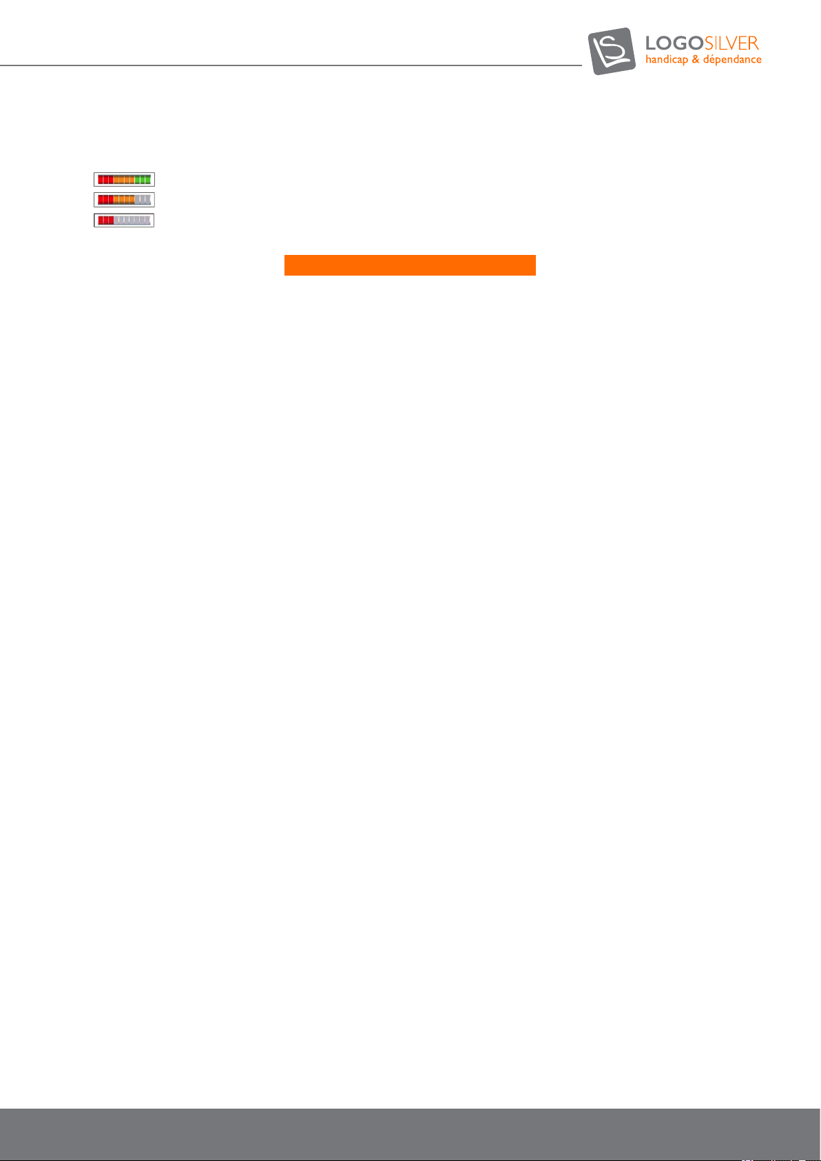
7.10.5. Battery gauge on the LCD screen
•
•
•
The batteries are charged if the battery gauge reads red, yellow and green.
You need to charge the batteries as soon as you can if the battery gauge only indicates red and yellow.
You must charge the batteries immediately if the battery gauge only indicates a steady or slowly ashing red.
How does the battery gauge work?
• The battery gauge lets you know what the remaining charge is in the batteries. The best way for you to use the gauge is
to know how it behaves as you drive the wheelchair. Like the fuel gauge in a car, it is not completely accurate, but it will
help you to avoid running out of «fuel».
• When you turn on the control system, the battery gauge gives an estimate of the remaining charge. The battery gauge
gives a more precise reading about a minute after you have started driving the Wheelchair.
• The level of charge in your batteries depends on how you use your wheelchair, the battery temperature and age. These
factors affect the distance you can travel in your chair. All wheelchair batteries will gradually lose their capacity as they age.
• If the measurement of the battery gauge appears to be falling faster than usual, your batteries may be exhausted. When
you change old batteries, replace them with batteries recommended by Magic Mobility. If you use another type, the
battery gauge is likely to be inaccurate.
7.10.6. Public transport
Gelled electrolyte batteries are approved by the FAA (Federal Aviation Administration) and can be transported safely
on-board aircraft, buses and trains. However, Magic Mobility recommends you check the requirements of the carrier in
advance. When you want to y with your chair, contact the airline to communicate the required information. Magic Mobility
has a brochure available on its website entitled «ying with your chair» which covers most related issues.
7.10.7. Disposal and recycling of batteries
If you encounter a damaged or cracked battery, contact your Logo Silver dealer for instructions on the safest way to get rid
of it. We advise you to contact your Logo Silver dealer who will have all the information you need to recycle your batteries.
41
User manual OUTCHAIR
09/2018
Page 42
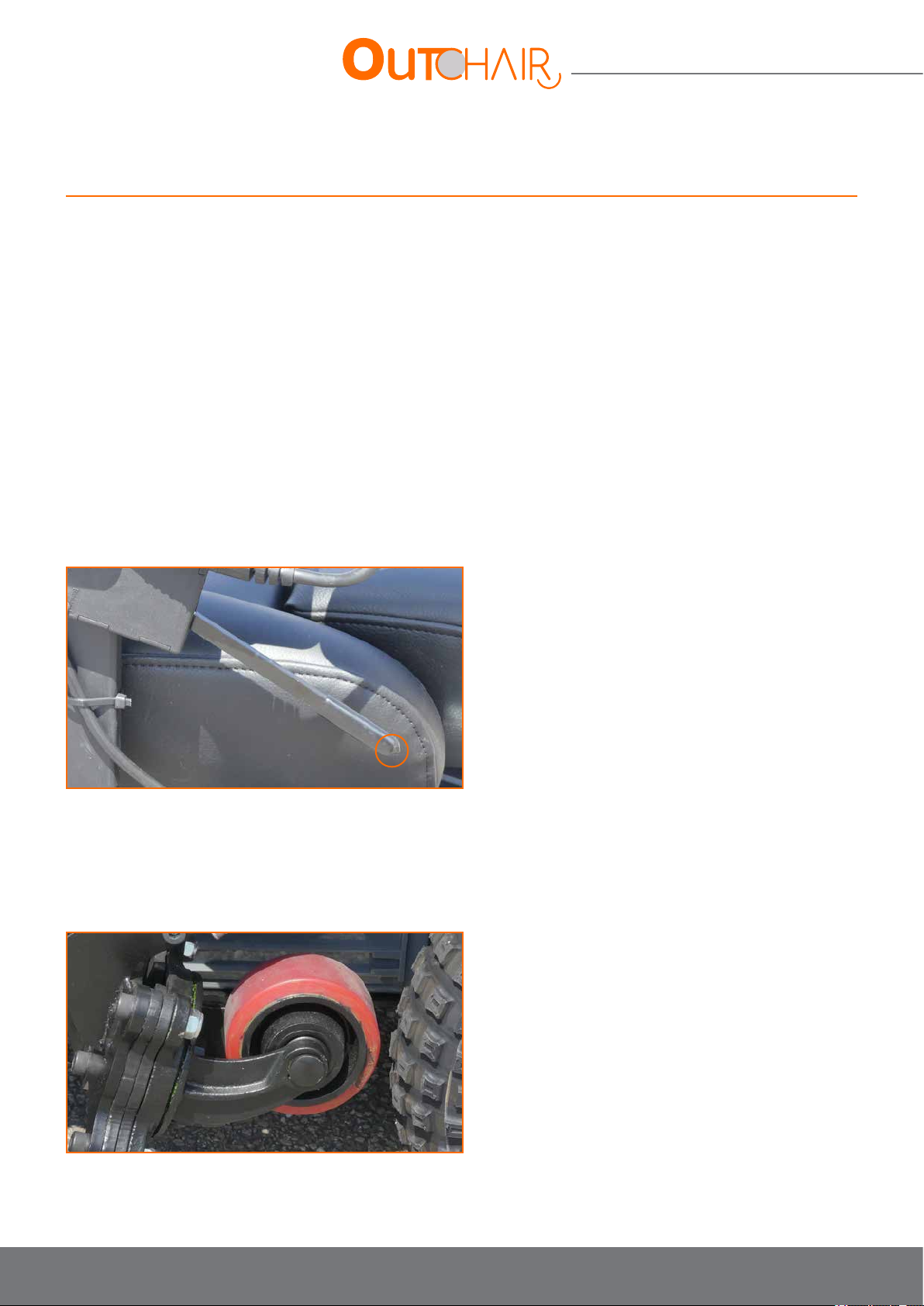
User manual
8. Options
8.1. Joystick CJSM2 with Bluetooth
See chapter 7.8.8. CJSM2-BT joystick.
8.2. Raised power legrests
Raised power legrests are controlled via the joystick by pressing the mode button. When you are in the mode screen you can control:
• The raising and lowering of both legrests by pressing right or left on the joystick to select the “leg raise” mode.
• The left legrest is raised and lowered by pressing right or left on the joystick to select the «raise left leg» mode.
• The right legrest is raised and lowered by pressing right or left on the joystick to select the «raise right leg» mode.
• The legs are raised by pushing the joystick forwards and they are lowered by pulling the joystick towards you when you
have selected the desired mode.
8.3. Steering lock
The steering lock allows you to lock the wheels straight to enable manoeuvres in reverse, over obstacles, into a vehicle, on
slippery surfaces...
This lock is activated and deactivated using the lever.
To lock the steering, rst put the front wheels as straight as possible and pull the lever upwards.
To unlock the steering; push the lever down and shift it to the side to prevent it from moving.
8.4. Casters
This option is only available with the Out Chair L (Long). The procedure for this option is explained in chapter 7.3. «Indoor»
driving prole with the caster option.
42
Page 43

8.5. Batteries
With the Out Chair S (short) there are two battery options:
• 2 x 80 Ah gel batteries or 30 km of driving autonomy
• 2 x 110 Ah gel batteries or 40 km of driving autonomy
With the Out Chair L (longer by 10 cm) there are 2 x 135 Ah gel batteries for 50 km of driving autonomy.
8.6. Recaro Seat
This high-end seat is available in the manual and electric version.
The manual version has backrest and lumbar tilt adjustment via knobs on the sides of the backrest.
The electric version has a power backrest tilt adjustment that can be controlled via the joystick by pressing the mode button
and selecting the “backrest tilt” mode.
8.7. Other optional elements
The other options or adjustments will be added to this notice as a related addendum in this chapter.
9. Malfunction and troubleshooting
9.1. Diagnosis and troubleshooting
Electronic repairs should only be carried out by authorized service providers. Improper or incorrect repair can result in an
unsafe adjustment to the wheelchair. Logo Silver accepts no responsibility or losses or damages of any kind that could result
from any improper or incorrect repair carried out.
The electronic system can detect any unusual circumstances concerning motors, brakes, wiring or the electronics module itself.
The security code number is indicated by a ashing error message with this code.
Depending on the severity, the system may allow or prohibit driving. In some cases, driving is only possible at reduced speed.
Display of safety circuit codes:
When the safety circuit begins to prevent wheelchair movement, a diagnostic screen will appear, or an LED will ash.
Penny and Giles have a full website to help you recover the security codes. If you have access to a computer, this can help you
identify simple problems yourself.
http://support.pgdt.com/Online-Diagnostics/Trip-Codes/R-net-Trip-Code-Database.aspx
Contact your Logo Silver provider and give them the information that is displayed on the diagnostic screen. This will help
determine how to solve the problem.
In addition, the following should be veried if possible:
• Turn off the joystick
• Make sure all connectors are securely connected and no wires are stuck
• Check that the engine brake is engaged
• urn on the joystick and try driving the wheelchair again. If the security circuit launches again, switch off the chair and do not
try use it again.
No security code displayed:
If the wheelchair cannot move or if it moves at a reduced speed while no security code is displayed on the screen, it is likely
that one of the lock switches has been activated for your safety.
Lock switches include; the seat inclination, the reclining backrest, the caster release.
The activation of one of these switches affects the driving performance of the chair. Return the seat to its upright position, make
sure that the seat incline is horizontal, retract the casters and check that the problem is resolved.
43
User manual OUTCHAIR
09/2018
Page 44

User manual
9.2. Solving common problems
• Centering the Joystick: When this error occurs, it is usually because the Joystick is off center before and during the
switching on of the control system. The screen «Joystick moved» will be displayed for 5 seconds, then an error will be
recorded if the joystick doesn’t release.
=> Make sure the joystick is centered and turn on the control system. It is better not to touch the joystick when it is being
switched on.
• Low Battery: This error occurs when the control system detects that the battery voltage is less than 16 V.
=> Check the condition of the batteries and the connections to the control system.
• High battery voltage: This error occurs when the control system detects that the battery voltage exceeds 35V. The most
common cause of this error is the overcharging of the battery or bad connections between the control system and batteries.
=> Check the condition of the batteries and the control system connections.
• Brake failure: This error occurs when the control system detects a problem with the magnetic breaks or their connections.
=> Check magnetic brakes, cables and connections to the control system
=> Check that the engine brake is not disabled (see section 7.4 Manual movement)
• Engine failure: This error occurs when the control system detects that the engine has been disconnected.
=> Check the motor, cables and connections to the control system
• Active Inhibition: This error occurs when one of the inhibitor switches is locked and active.
=> Restart the power. This will reset the lock mode, which can resolve the error.
=> Check all cables and switches connected to the inhibitor input indicated.
• Standby: The control system enters sleep mode when it has been idle beyond the Standby time set.
• Charging: This message is displayed when the control system detects that a charger is connected to inhibitor input 1 or
3. The battery charge screen appears when a charger is connected.
=> Disconnect the charger from the wheelchair.
• Incorrect wiring: This error occurs when the control system detects a fault in the wiring between two modules.
=> Check the continuity of all cables and connections as well as for the absence of pinch points
=> If a cable appears visibly damaged, replace it and restart the armchair cable.
=> Contact your service agent to obtain a replacement cable.
44
Page 45

10. Care and maintenance
10.1. General recommendation
Note
Only Logo Silver spare parts can be used. Failure to comply with this condition results in the loss of warranty rights.
If you encounter problems during maintenance, consult Logo Silver or your dealer.
The Out Chair should be checked once a year by qualied staff approved by Logo Silver.
If you notice symptoms such as a noisy motor, a frayed wiring harness, damaged connectors, uneven tyre wear, unusual movement, a
broken part or any other troubling signs between two maintenance periods, please contact your Logo Silver dealer immediately.
Avoid exposing your electric wheelchair to moisture (rain, snow, fog, salt water or cleaning products). Such exposure could damage your
chair - see section 10.2. Protection against corrosion. If your electric wheelchair comes into contact with water, sponge it as well as
possible with a cloth and let it dry for 10 to 12 hours in a warm room. Check that the joystick and brakes are working properly before
using the wheelchair. If you have any doubts or notice any malfunction in your chair, please contact your Silver Logo dealer.
Do not leave the wheelchair exposed to rain or the elements. Do not use the wheelchair in the shower and do not leave it in a wet
bathroom while you take a shower.
Do not store the wheelchair outdoors or in a moist environment.
Direct exposure to rain or moisture will cause electrical and mechanical malfunctions and risks rusting the chair prematurely.
Avoid hitting the controller, especially the joystick.
Clean the controller regularly.
Avoid exposure to extreme temperatures.
Place the controller cable so that it cannot get caught in the seat frame or base of the electric wheelchair.
Do not charge the chair under extreme temperatures.
45
User manual OUTCHAIR
09/2018
Page 46
User manual
Some parts of the wheelchair are vulnerable to extreme temperatures. It is possible that the batteries could freeze. The temperature
at which the batteries freeze depends on a certain number of factors, including their chemical composition, charge level and frequency
of use. When the temperature is high, the electric wheelchair can run at a scaled down speed. This is a safety function built into the
controller to protect the motor and other components.
The conguration of the electric control box must ONLY be carried out by an individual authorised by Logo Silver. Final controller settings
may affect other wheelchair activities.
If a non-certied individual performs repairs on any of these devices, the warranty will be void and the equipment may be damaged.
Do not modify or have your wheelchair modied in any way that is not authorized by Logo Silver. Unauthorized modications constitute
a remanufacturing of the wheelchair. The person or group making the changes will be fully responsible for the wheelchair in accordance
with the Therapeutic Goods Act (TGA).
10.2. Protection against Corrosion
The power chair has been manufactured using a variety of processes to resist corrosion. Although efforts have been made to
ensure the long-term durability of the product, we cannot guarantee the absence of corrosion on the chair throughout its
service life. Prevention, protection and maintenance measures are essential to reduce the risk of corrosion on the wheelchair.
The most common causes of corrosion of the electric wheelchair are:
• Paint or undercoat peeling caused by impacts from stones and other hard objects.
• Accumulation of salt, soil and moisture on the frame components.
• Exposure to highly corrosive environments such as seaside, rivers and streams
10.2.1. Peeling paint
If the paint on the frame of your power chair or other metal components is peeling off and the metal underneath is visible,
the following procedure is recommended to repaint the affected area:
• Lightly sand the exposed area to atten and remove any remaining paint chips. Be sure to remove any visible surface corrosion.
• Apply a cleaning solvent to remove dust, dirt and grease.
• Apply primer to the area to be repainted.
• After a suitable drying time, apply the touch-up paint, making sure it covers all exposed areas. Once dry, the area should
now be protected from corrosion.
• If it is not practical to repaint the area, use a «rust converter» type product to neutralize rust and prevent it from
spreading.
10.2.2. Beach, salt water and coastal areas
• Salt water and the surrounding environments are highly corrosive.
• Exposure to coastal areas will increase the risk of corrosion, even if the chair is not used on the beach. Seaside air usually
contains much more salt than on inland. The highest corrosion rates are generally found about 500 meters from the coast.
If you live near the coast or regularly use the wheelchair near the beach, please refer to sections 10.2.4 and 10.2.5. below
for maintenance tips.
46
Page 47
10.2.3. Snow and Ice, Salt Roads and Pathways
Avoid using the wheelchair on salted surfaces if possible, as salt can have a detrimental effect on wheelchair components. If
the chair has been used on wet, icy or salty surfaces, see sections 10.2.4 and 10.2.5. below for maintenance tips.
10.2.4. Cleaning after use
If the electric wheelchair has been used in a coastal, wet or salty environment, we recommend that you clean it thoroughly
to reduce the risk of corrosion. Once inside, clean all parts of the chair with a cloth soaked in hot water. The chair should
not under any circumstances be pressure washed. It must then be stored in a warm and dry environment. It can also be
helpful to remove as much sand and / or salt as possible.
10.2.5. Preventative Maintenance
Before using your chair in a moist or corrosive environment, it is advised you protect it by carefully coating all metal
surfaces with a waterproong product. This product may for example be an oil-based aerosol (such as WD40) or a
lanolin-based dispersant (such as Lanotec). This coating should act as a barrier between the water and the painted metal
surfaces of your electric wheelchair. A lubricant (such as WD40) can be sprayed onto the tilt mechanisms to protect them.
The underside of the wheelchair (battery compartment and frame components) can also be sprayed with the aid of a ramp
or another approved lifting device.
IMPORTANT
Your wheelchair is equipped with electric motors and must NEVER be driven into water, a river, a stream or the sea.
10.3. Daily checks
Joystick: Once the control system is turned off, check that the joystick is not distorted or damaged and that it returns to the
center when you release it. Make sure that the joystick boot is not torn or cracked and that all electrical connections are
properly carried out.
STOP
Do not use the joystick if the boot is torn or cracked. If the joystick boot is torn or cracked, have it replaced IMMEDIATELY.
10.4. Weekly Checks
Electric Brakes: This test must be performed on a at surface with at least one gauge of free space around the chair.
• Turn on the control system.
• Check that the battery gauge stays on or ashes slowly after one second.
• Push the joystick slowly forward until you hear the electric brakes come into operation. It is possible that the chair might
start to move.
• Release the joystick immediately, you should hear each electric brake engage after a few seconds.
• Repeat the test three times by pushing the joystick backwards, left and right.
Operation: If your wheelchair is equipped with headlights, turn signals or a seat adjusting cylinder, check that they are working
correctly.
Connectors: Make sure all connectors are plugged in and are not damaged.
Cables: Inspect the cables to make sure they are not damaged.
Joystick Boot: Inspect the rubber boot around the base of the joystick to make sure it is not damaged or cracked. Check
visually only, do not handle the boot.
Assembly: Make sure the controller is securely attached to your wheelchair. Do not over-tighten the screws.
Tyre Pressure: Make sure the tyre pressure meets the specications given in section 7.5.5. pneumatic pressure. Check tyre
wear.
STOP
If any of these checks reveal a problem, please contact your Magic Mobility dealer for repair.
47
User manual OUTCHAIR
09/2018
Page 48

User manual
10.5. Monthly checks
Armrests and lateral sections :
• Check the fasteners.
• Check that the armrests can be adjusted without excessive effort.
• Check that the armrests are locked in place.
Legrests:
• Check that the legrests click into place properly.
• Check that the adjustment options are working properly.
Tyres:
• Check that the tyre pressure is adequate.
• Tyre wear varies signicantly depending on the road surface. Frequent use on aggressive surfaces such as asphalt results in
premature wear.
Front casters / front wheels:
• Check that the front wheel steering turns freely.
• Check the attachment of the casters and suspensions.
Check that there isn’t excessive pivot clearance.
Electronic system / Electrical system:
• Check the condition and correct positioning of the wiring and connections.
Seat tilt:
• Check that the two seat tilt bump stops are in good condition.
• Check that they are both in contact when the seat is at its maximum inclination.
• See section 10.9. Seat tilt malfunction.
Mechanics:
• Check the tightness of the screws.
• Check that the wheels are correctly positioned on their axle.
• Check that the rotation of the rear axle is sufcient.
• Check that the rear wheels turn without buckling.
• Check that there is no excessive clearance or unusual sounds.
10.6. Annual check
Once a year, have your wheelchair checked by your dealer who will carry out a full maintenance. Regular maintenance can help
to quickly detect damaged or worn parts and thus promote normal wheelchair operation.
10.7. RTyre/Tube Repair
Note
Direct exposure to sunlight (UV) accelerates tyre aging. Regardless of their wear, the tyres must be changed every 2 years.
48
Page 49
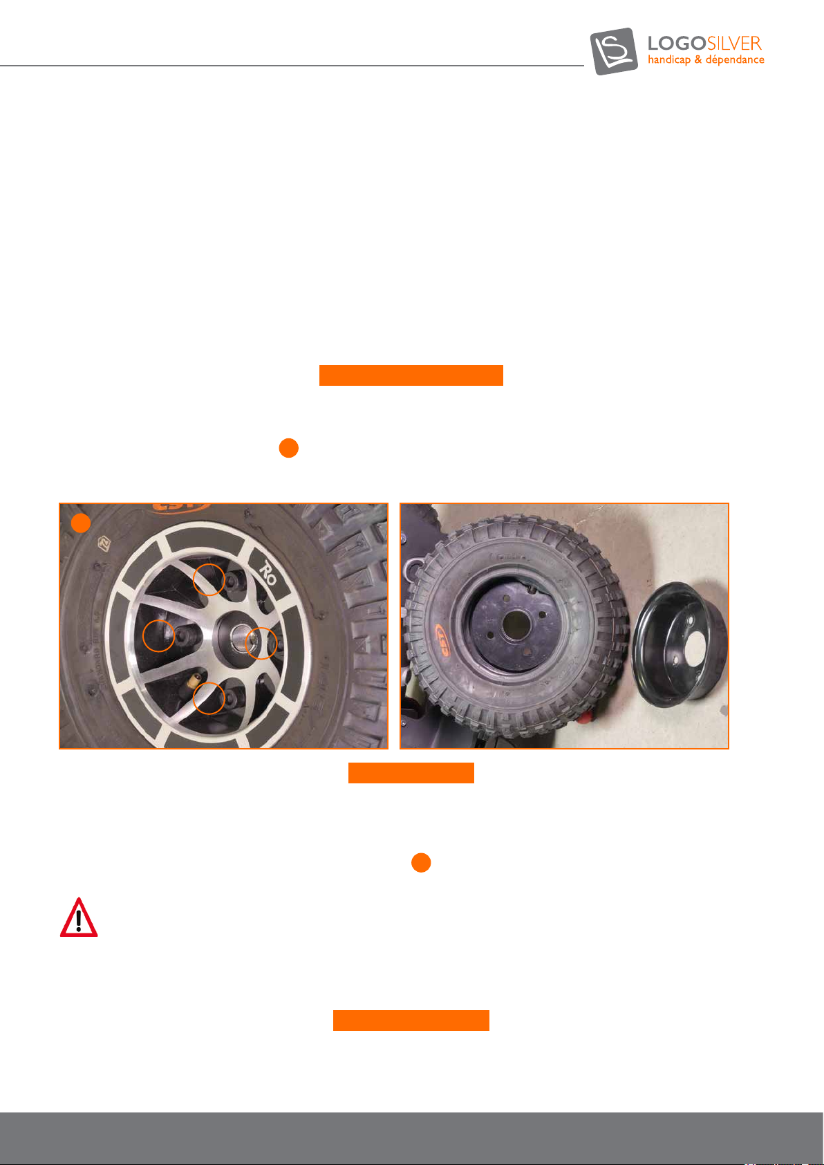
Tools:
• A Hexagonal Allen key, 8 mm
• A shim
• A 17 mm at wrench
• A large at screwdriver
• A torque wrench
• A repair kit for tyre with inner tube or a new tube.
• Talc
• Thread sealing lacquer
Disassembling the wheel:
• Lift the wheelchair and prop it to the side of the corresponding wheel.
• Turn off the power (ON / OFF key).
• Unscrew the 4 screws indicated at
26
, being careful to loosen the 2 locknuts behind the front rim.
• Remove the wheel from the wheel hub.
26
Wheel assembly:
The assembly is carried out in reverse order. Make sure that the wheel is remounted on the same side and in the same direction
as it was during disassembly.
• Tighten 4 screws to 30 Nm
• Tighten both locknuts on two of the four screws indicated at
26
.
Warning
If a wheel is not tight enough during assembly and / or the locknuts are not in place it may come off during a movement and cause
injury.
Repairing the Wheel:
• Remove the wheel following the previous procedure.
• Unscrew the valve cap.
• Release the air in the tyre by pressing the spring rod into the valve.
49
User manual OUTCHAIR
09/2018
Page 50
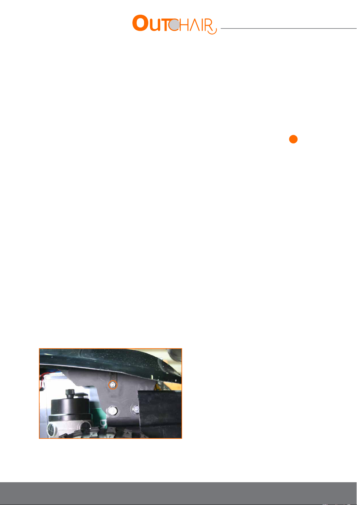
User manual
• Remove half of the tyre rim by levering a large at screwdriver all around between the tyre skirt and the rim edge.
• Repeat the same operation for the other part of the rim.
• Remove the inner tube from the tyre casing.
• Repair the tube and put it in place or replace it, making sure that there is nothing that might pierce the tube in the tyre. (If
the old inner tube needs to be repaired and put back in place and if it has been wet during the repair, it is best to apply talc).
• Inate the tube slightly and place it in the rim.
• Place the outer rim half on the tyre, being careful to pull the valve out of the hole provided for this purpose.
• Place the second rim half (sheeting) on the tyre, making sure to align the holes of the 4 screws indicated in 26.
• Reassemble the wheel on the hub following the previous procedure.
• Inate the tyre to the prescribed air pressure.
• Screw in the valve cap.
10.8. Battery replacement
Tools needed:
• A pair of pliers
• An 11” wrench
• 2 at 10” wrenches
• 2 at 17” wrenches
• 1 shim
• A 5 mm BTR wrench
• A 6 mm BTR wrench
• A 8 mm BTR wrench
• A torque wrench
10.8.1. Battery removal
• Disarm the circuit breaker
• On the Out-Chair L, remove the two rear mudguards by unscrewing the mudguard screws.
50
Page 51
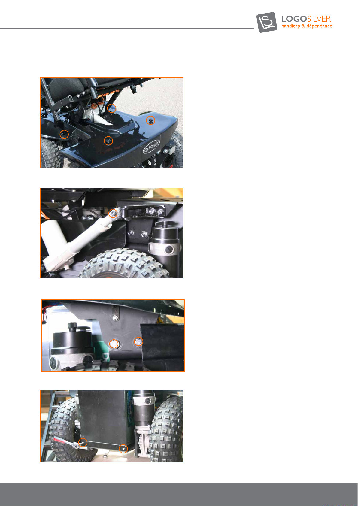
• On the Out Chair S, remove the complete/full body/bodywork by unscrewing the four knobs and tilting the seat.
• If you have the castors option, unscrew the cylinder screw.
• Unscrew the two screws to each side while holding onto the rear cover in order to remove it.
• Unscrew the two screws on the back plate to remove it, this will give you access to the rear battery.
51
User manual OUTCHAIR
09/2018
Page 52
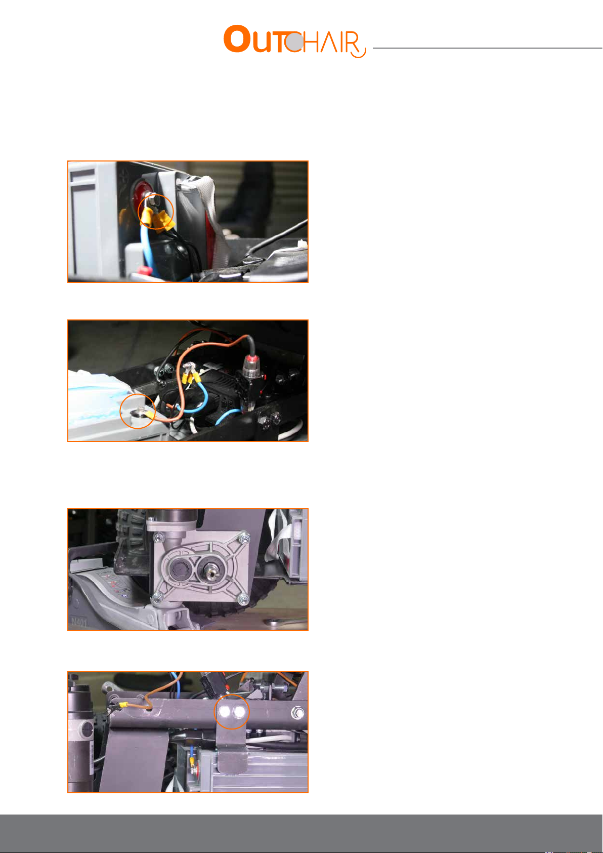
User manual
• Before unscrewing the terminals from the batteries, note the position of each cable for future reassembly.
• Unscrew the upper terminal (+ terminal) of the rear battery being careful not to cause a short circuit (protect the
terminals with tape after removing them).
• Move the rear battery and place it on level ground it in order to unscrew the lower terminal (terminal -).
• Remove the rear battery
• Hold the right rear engine in place and remove the right rear wheel following the wheel disassembly procedure
previously described.
• Unscrew the two holding screws of the right battery.
52
Page 53
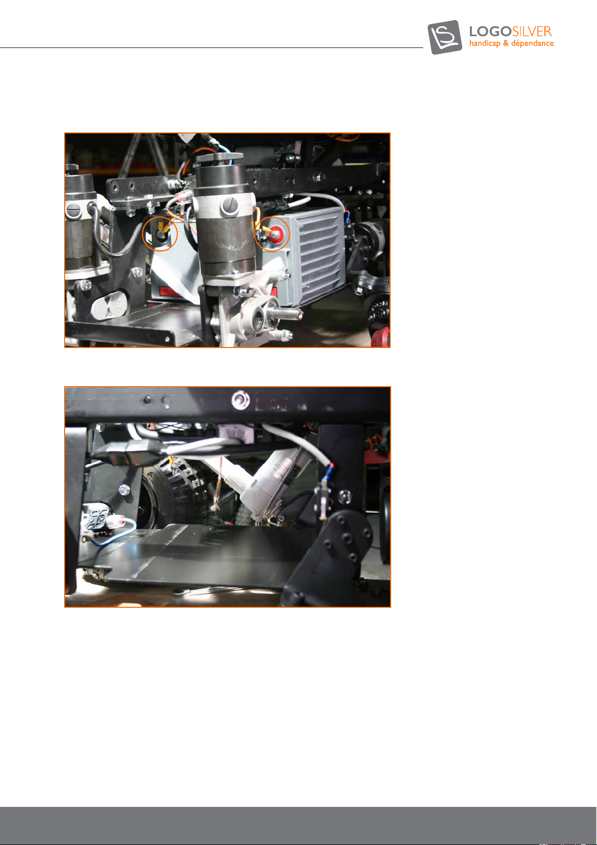
• Disconnect the terminals from the central battery.
• Remove the central battery.
10.8.2. Battery reassembly
• This is the opposite operation taking care to connect the cables as they were before disassembly.
53
User manual OUTCHAIR
09/2018
Page 54
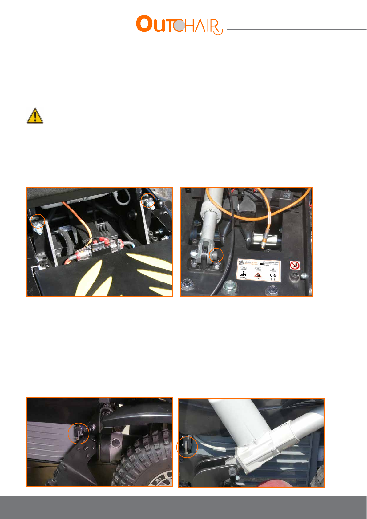
User manual
10.9. Seat tilt malfunction
• Every month it is important to check that the two bump stops are in good condition.
• Every month it is important to check that they are both in contact when the seat incline is at its maximum
• If this is not the case, contact your authorized Logo Silver dealer to change the stoppers and / or their setting.
Warning
Do not attempt to adjust and / or change these stoppers yourself, you may cause the maximum incline of the seat to malfunction and
you risk tipping your chair over.
• If your seat leans too far forward and parts come into contact with your body, you must adjust the position of the front
attachment of the seat cylinder.
Seat tilt bump stops Seat cylinder front attachment
10.10. Caster (optional) malfunction
• If the front wheels rotate while the casters are out, the left switch may be disconnected and / or incorrectly adjusted. It
is also possible that the relays need to be changed.
• If the speed limit is at 2.5 km / h when your casters are fully retracted, it is possible that the right switch is disconnected
and / or incorrectly adjusted.
• If you are not limited to 2.5km / h when your casters are out, do not use a speed higher than this one and contact us.
• All repairs to switches and relays must be performed by an authorized Silver Logo dealer.
Right Switch Left Switch
54
Page 55
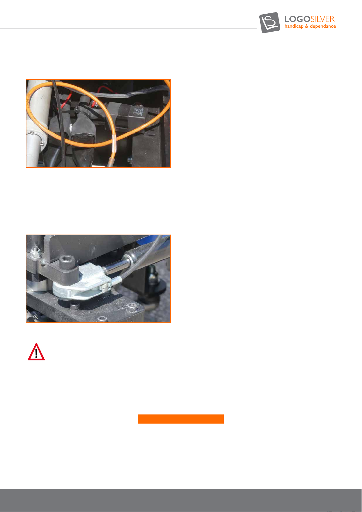
Front wheel cutoff relay.
10.11. Steering lock (optional) malfunction
• If you notice that the steering lock is not effective enough you can adjust the cable tension by turning the adjustment dial
on the control.
• If the steering lock stays stuck after unlocking the joystick, it is possible that something (such as the bodywork) is blocking
the cable of the actuator release head..
Actuator release head cable
10.12. Cleaning the vehicle
Warning
Risk of damage to the electronic system! Risk of malfunction! When cleaning the Out Chair, water should not come into contact with
electronic components and batteries.
Do not use aggressive cleaning agents, solvents or hard brushes. The Out Chair should be cleaned regularly, regardless of use or degree
of soiling.
When cleaning the vehicle:
• Use only a damp cloth and a mild cleaning agent.
• Do not use abrasive products for cleaning.
• Do not use a pressure washer.
55
User manual OUTCHAIR
09/2018
Page 56

User manual
11. Warranties
Certicate of Warranty: The chair is warranted for a period of 2 years from the date of delivery, excluding corrosion, worn
parts (tyres etc), abnormal use, non-compliance with the instructions for use. Only the batteries are guaranteed for a period
of 1 year (excluding the time of immobilization for a possible repair of the chair). The warranty covers any defect in the
construction or quality of the raw material and components, under normal conditions of use (excluding normal wear of the
parts). The warranty is limited to the repair or free exchange of parts and subassemblies recognized as defective (parts, labor
and transport), after inspection by an authorized representative.
Warranty repairs must be authorised and performed by an approved supplier. You must not return parts without obtaining prior
authorization.
This warranty does not apply in case of malfunction of the product due to:
• accidental shocks or accidents
• negligence
• abnormal use
• improper maintenance
• modications made without the authorization of the manufacturer
• use not in accordance with the instructions in the user guide supplied with the product or which do not correspond to the
product specications
• withdrawal / erasure of the serial number
• cold storage or batteries left completely empty for a long period
12. Disposal
Note
If you dispose of the Out Chair, all components and materials must be disposed of in an environmentally friendly manner, and in
accordance with the sorting of waste or recycling.
• Observe the environmental protection regulations in force in your country.
• Used batteries are taken back by your dealer or Logo Silver.
• The Out Chair can be returned to Logo Silver for recycling.
32 rue de Comboire - 38130 Echirolles - France
+33 (0)4 76 21 22 19
[email protected]
www.logo-silver.fr
Supplied by:
56
 Loading...