


USER MANUAL
LBSM-MD-ML-CLS-001
VC1712-01
www.logosbio.com

DISCLAIMER
The contents of this document are subject to change without notice.
The CELENA® S Digital Imaging System is an electrical laboratory instrument for scientific research use only.
It is not a medical, therapeutic, or in vitro diagnostics device.
Do not disassemble the device on any occasion as this will invalidate your warranty.
TRADEMARKS
The trademarks used in this document are the property of Logos Biosystems, Inc. unless otherwise specified.
LED Filter Cubes are LTC Licensed Products provided under an intellectual property license from Life Technologies Corporation.
© 2017 Logos Biosystems, Inc. All rights reserved.

Table of Contents
Getting Started ...................................................................................................................................................................................... 3
Basic Operation .................................................................................................................................................................................... 6
Imaging basics ........................................................................................................................................................................................... 6
Iris diaphragm ....................................................................................................................................................................................... 6
Phase annuli .......................................................................................................................................................................................... 6
Imaging control panel ......................................................................................................................................................................... 7
Capture images in CAPTURE mode .................................................................................................................................................. 8
Image Editing and Analysis ................................................................................................................................................................. 9
CAPTURE control panel............................................................................................................................................................................. 9
Images panel ........................................................................................................................................................................................ 9
Analysis panel ....................................................................................................................................................................................... 9
Data panel ............................................................................................................................................................................................ 9
Save images ........................................................................................................................................................................................ 10
Z-stack Imaging .................................................................................................................................................................................. 11
Z-STACK mode .......................................................................................................................................................................................... 11
Capture images in Z-STACK mode ................................................................................................................................................. 11
View/delete images .......................................................................................................................................................................... 11
Process images ................................................................................................................................................................................... 12
Time Lapse Imaging ........................................................................................................................................................................... 13
TIME LAPSE mode ..................................................................................................................................................................................... 13
Capturing time lapse images ........................................................................................................................................................... 13
View/save images .............................................................................................................................................................................. 13
Process images ................................................................................................................................................................................... 14
Cell Counting ...................................................................................................................................................................................... 15
AUTOMATED CELL COUNTER .................................................................................................................................................................. 15
Automated cell counter control panel .......................................................................................................................................... 15
Protocol parameters and settings ................................................................................................................................................... 15
Counting cells in automated cell counting mode ....................................................................................................................... 16
View/save results ................................................................................................................................................................................ 16
MANUAL CELL COUNTER ........................................................................................................................................................................ 17
Manual cell counting ......................................................................................................................................................................... 17
Saving Images .................................................................................................................................................................................... 17
FILE MANAGER ......................................................................................................................................................................................... 17
Settings ................................................................................................................................................................................................ 18
Settings ...................................................................................................................................................................................................... 18
Maintenance ........................................................................................................................................................................................... 19
Troubleshooting........................................................................................................................................................................................ 20
Safety Information............................................................................................................................................................................... 21
Instrument safety...................................................................................................................................................................................... 21
Personal safety ......................................................................................................................................................................................... 22
Instrument symbols .................................................................................................................................................................................. 22
Safety standards ...................................................................................................................................................................................... 22
Product Specifications ........................................................................................................................................................................ 23
Ordering Information .......................................................................................................................................................................... 24
Purchaser Notification ........................................................................................................................................................................ 26
2
Getting Started
Product contents
Product contents
Your CELENA® S is shipped with the following components:
Filter cubes (as ordered)
Objectives (as ordered)
Insert plate
Vessel holder frame
Universal Holder
25 mm x 75 mm slide holder, two positions
Power cord with AC adapter
HDMI cable
Wireless mouse
USB drive, 64 GB (includes the user manual and installation guide)
Tool kit
Inspect the product package upon delivery to ensure that all components have been included. If
anything is missing, contact your local sales representative. Damage that may occur during
shipping and handling is not covered by warranty and must be filed with the carrier.
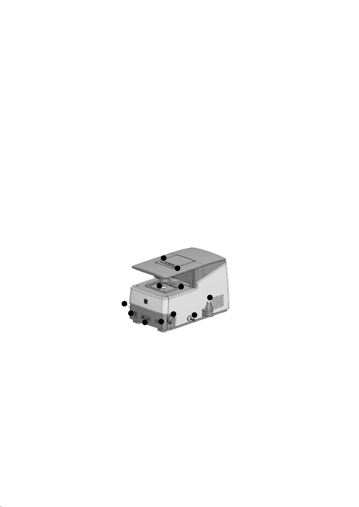
Product description
CELENA® S
Digital Imaging System
The CELENA® S Digital Imaging System is a digital microscope that pairs high-performance optics
and a user-friendly software interface to create a smooth and seamless user experience. Anyone
can obtain sharp and beautifully vivid images in seconds with the CELENA® S.
① Iris diaphragm slider
② Phase annuli slider
③ Insert plate
④ Vessel holder frame
⑤ USB ports (2)
⑥ Objective turret wheel
⑦ Power button
⑧ Focus knobs
⑨ Filter cube selection tail
⑩ Stage control knobs
4 3 5 6 7 8 9
1
2
8
10
3
Setting up
Unpacking
Lift the CELENA® S out of its box by grasping its base firmly with both hands at diagonally
opposite ends. Place it on a clean, level, and sturdy surface.
Do not hold or lift it by its top cover (where ① and ② are located on the CELENA® S).
Avoid vibrations from other devices.
Leave sufficient space around the instrument for proper ventilation and to prevent
overheating.
Do not expose the instrument to intense ultraviolet light.
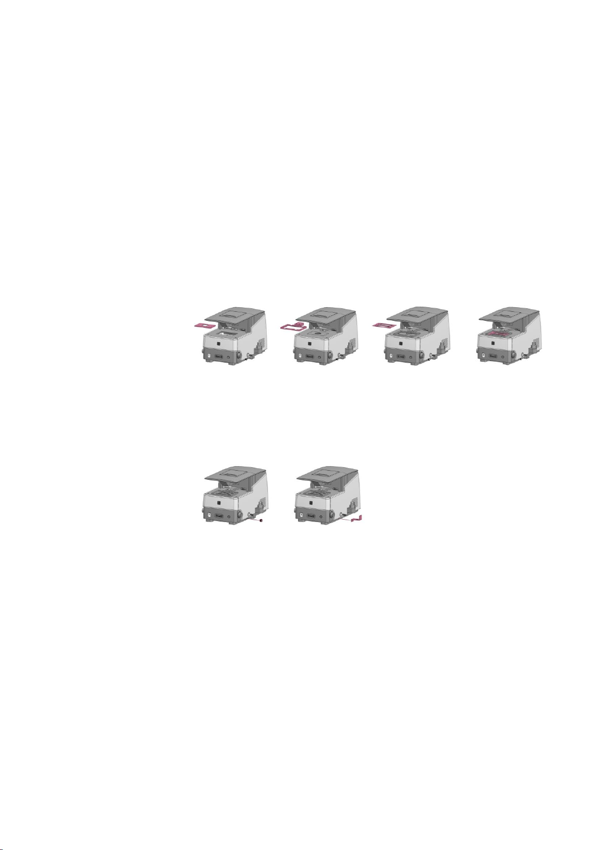
Stage assembly
1. Place the insert plate onto the stage with the flat side up and the grooved side down.
2. Move the vessel holder frame arm to the front of the stage using the stage control knobs.
3. Attach the vessel holder frame to the vessel holder frame arm. The frame will snap into
place because of the magnets in the vessel holder frame arm.
4. Move the vessel holder frame to the center of the stage using the stage control knobs.
5. Place the desired vessel holder into the vessel holder frame.
Selection tail guard
The selection tail guard keeps the filter cube selection tail from moving during shipping.
1. Unscrew the screw from the selection tail guard.
2. Pull the selection tail guard away from the instrument. Store in a safe place for future use.
4

Connections
1. Remove the bubble wrap protecting the camera’s USB cable
*
. Insert into the bottom USB
port at the back of the CELENA® S. Make sure the connection is secure.
2. Plug the wireless mouse dongle into the top USB port at the back of the CELENA
®
S.
3. Connect an HDMI-compatible monitor to the CELENA
®
S via the HDMI cable.
4. Insert the connector of the AC adapter into the power inlet of the instrument. Connect the
power cord to the AC adapter. Connect the power cord to an electrical outlet.
Make sure the power cords are appropriate for your region.
Always use power cords and AC adapters provided by Logos Biosystems.
*For the EU version of the CELENA
®
S, the camera cable is internalized and the inactive D-SUB port has been removed.
Turn ON the CELENA® S
To turn on the instrument, push the power button.
Turn the monitor on.
The initial display will be in CAPTURE mode. The CELENA® S is ready to use.
Shut down the CELENA® S
To shut down the instrument, click the power button located at the top left corner of the screen.
The Z-stage is docked for safety when the CELENA® S shuts down.
In the case of an emergency or system error, push the power button on the front of the
instrument to power off the CELENA® S.
CAMERA
CABLE
Imaging control panel
Date & time
Power button
Settings
Menu-based control panel
Menu bar
5
Basic Operation
Imaging basics
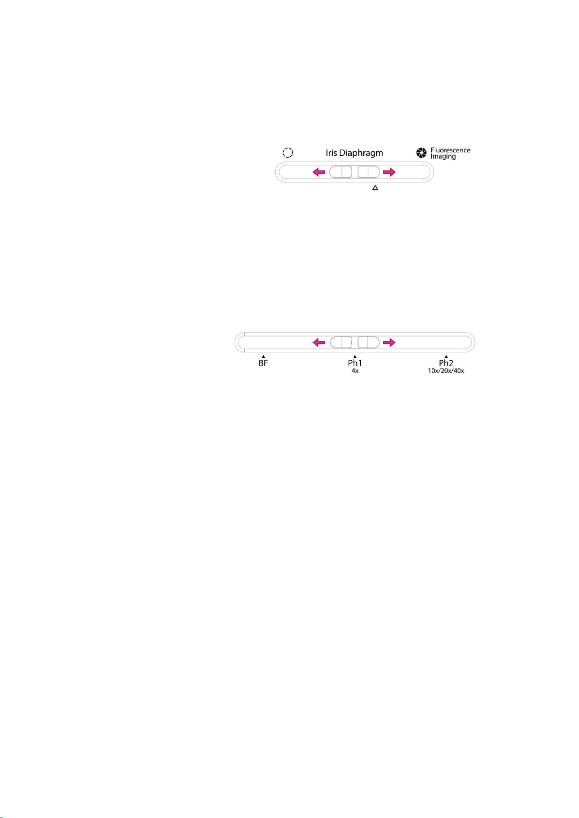
Iris diaphragm
Move the diaphragm slider to adjust the amount of transmitted light to reach the sample.
Opening or closing the iris diaphragm regulates the resolution and contrast of an image.
For transmitted light imaging, slide the diaphragm slider to the left.
This opens the diaphragm to allow in the maximum amount of light and increase resolution.
For optimal fluorescence imaging, slide the diaphragm slider to the right.
This closes the diaphragm to allow in the minimum amount of light and increase contrast.
For automated cell counting, slide the diaphragm slider to the Δ mark (2 cm from the right).
This allows the optimal amount of light for dye exclusion based cell counting.
Phase annuli
The phase annuli slider can be adjusted for brightfield or phase contrast imaging with the three
annuli for transmitted light imaging.
For brightfield imaging, move the phase annuli slider to BF.
For phase contrast imaging at 4X, move the phase annuli slider to Ph1 4x.
For phase contrast imaging at 10X, 20X, or 40X, move the phase annuli slider to Ph2
10x/20x/40x.
6
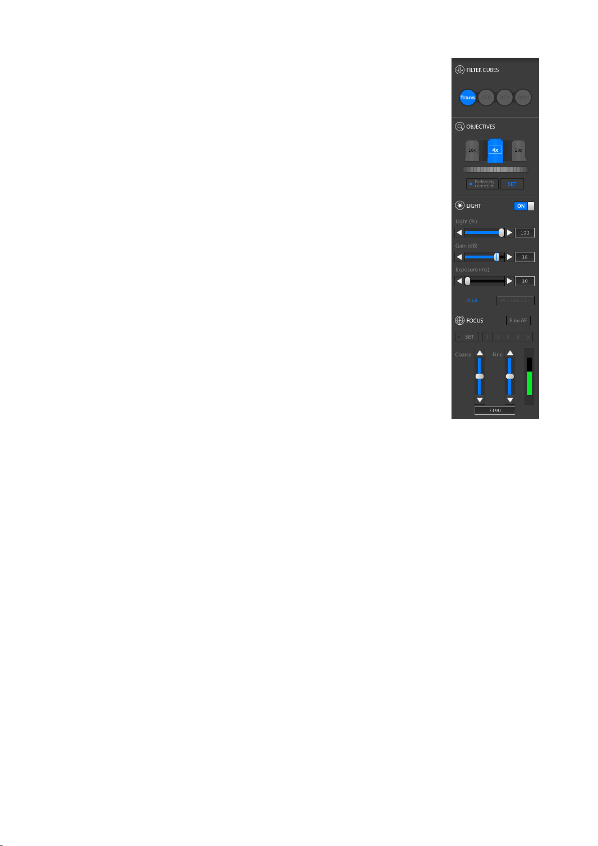
Imaging control panel
FILTER CUBES panel: The filter cubes panel shows the three
interchangeable filter cubes for fluorescence imaging and one white
filter cube for transmitted light imaging. The selected filter cube is
highlighted in blue. Each filter cube can be renamed and its
pseudocolor selected in the Settings.
To select a filter cube, move the filter cube selection tail in or out.
OBJECTIVES panel: The objectives panel shows the selected objective
and its adjacent objectives. The selected objective is highlighted in
blue. The position, magnification, numerical aperature, manufacturer
and a description of each objective may be modified in the Settings.
To select an objective, turn the objective turret wheel.
Due to the significant differences in objective lengths, take care when
turning the objective turret:
1. Lower the turret by using a preset focus position, the coarse
focus slider, or the coarse focus knob.
Caution! Lower the objective turret sufficiently or the
objectives will hit the insert plate and may be damaged.
2. Turn the turret to the desired objective.
3. Raise the turret using a preset focus position, the coarse focus
slider, or coarse focus knob.
Parfocality correction compensates for deviations along the focal
plane between different objectives. This feature helps maintain focus
when switching to a different objective. The CELENA® S is
precablitrated for the objectives installed at the time of order.
To turn parfocality correction on or off, click Parfocality correction.
Calibrate all objectives when you add or change objectives.
To calibrate:
1. Click LIVE.
2. Turn off Parfocality correction.
3. Place a slide onto the stage.
4. Select an objective.
5. Focus as sharply as possible on the sample and click SET.
6. Repeat with the next objectives.
Important! Parfocality correction can only be used with objectives corrected for the
same vessel bottom thickness (i.e. long working distance objectives cannot be
calibrated with coverslip-corrected objectives).
LIGHT panel: Use the light panel to control the intensity (%), gain (db), and exposure (ms) of the
selected filter cube. The current pixel depth is displayed in the panel and may be changed in the
Settings.
To turn the light source on or off, click the ON/OFF switch.
Light (%) is the intensity of the LED. Gain is the camera’s amplification of the signal. The gain is
analog up to 18 dB, meaning that signal will increase independently of the noise. Values above
18 dB are digital, meaning that both signal and noise will increase. Exposure is the amount of
time that the camera shutter is open to allow light into the sensor.
To adjust values, drag the bars, click the arrowheads, or turn the mouse wheel while hovering
over the sliders.
To colorize images, click Pseudocolor. Pseudocolor can be applied before or after capturing the
image.
7

FOCUS panel: Use the focus panel to focus and to preset focus positions. The preset focusing
speed and distance moved can be adjusted in the Settings.
To focus, manually manipulate the focus knobs or use the sliders in the focus control panel. Drag
the bars, click the arrowheads, or turn the mouse wheel while hovering over the sliders.
Click Fine AF to finely tune focus. The Fine AF Z-scan range can be adjusted in the Settings.
The focus memory feature allows the user to preset focus positions:
1. Move the focal plane to the desired position (move the objective turret) and click the SET
button. The SET button is highlighted in blue when selected.
2. Select the number that you want the position stored on. A keyboard will appear on the
screen. Label the position as desired (e.g. 10X e coli).
Important! Do not touch the focus knobs during the process.
3. Repeat the process for the various positions you want stored. Numbers with stored
positions will be highlighted in blue.
4. Hover over the set numbers to see their labels. Select a number to move the objective to
the preset position.
Preset focus positions may be erased in the Settings.
Capture images in
CAPTURE mode
1. Place the sample into the appropriate vessel holder.
2. Adjust the diaphragm slider as needed.
3. Adjust the phase annuli slider as needed.
4. Select CAPTURE in the menu bar.
5. Select an objective.
6. Select an LED filter cube.
7. Click LIVE.
8. Adjust the light intensity, gain, and exposure as needed.
9. Adjust the focus as needed.
10. Readjust the light intensity, gain, and exposure as needed. Activate the Pseudocolor
function as needed.
11. Capture the image by clicking CAPTURE.
12. Repeat steps 6-10 as needed.
8
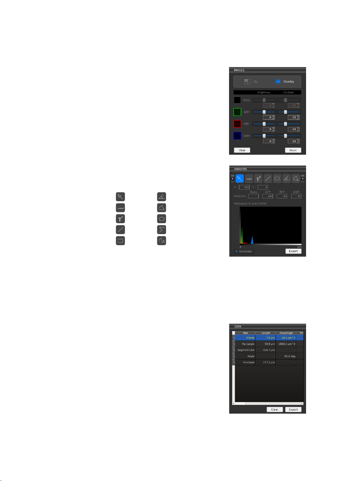
Image Editing and Analysis
CAPTURE control panel
Images panel
Use the IMAGES panel to adjust the brightness and
contrast in each channel.
To see the all the channels separately, click Tile. For a
merged image of all the channels, click Overlay. In the
Overlay view, click the thumbnail next to each channel
to hide or show it in the merged image.
Adjust the brightness and contrast of each channel
using the respective sliders or the text boxes.
To undo image adjustments, click Reset.
To delete all captured images, click Clear.
Analysis panel
Use the ANALYSIS panel to add annotations and analyze
captured images using the available tools.
Annotation tools
Select
Angle Scale bar
Polygon
Text Ellipse
Line Segmented line
Rectangle
Freehand
The select tool can be used to select and manipulate
annotations. Right click on an annotation to change properties such as color and size as well as
to copy, paste, and delete the annotation. Double click to deselect the annotation.
The ANALYSIS panel shows the X, Y position of the cursor and the light intensity of that position.
The histogram & line profile is a graphical representation of tonal values. To save individual
histograms and line profiles as a CSV file, click the Export button underneath the graph.
To show or hide all of the annotations made, click the Annotate button.
Data panel
The DATA panel shows you values for measurements
made with the annotation tools in the ANALYSIS panel.
To view all measured values, use the scroll bars.
To clear all measured values, click Clear.
To export measurement data as a CSV file, click Export.
9

Save images
To save the image(s), click SAVE.
In the save window, choose:
File/folder name
File path
File type: TIFF, JPEG, BMP, or PNG
To save as a folder
Image color: Monochrome or pseudocolor
Image type: single channels, overlay, annotated
When Quick Save mode has been enabled, the CAPTURE button becomes the CAPTURE &
QUICK SAVE button and images are saved immediately at the moment of capture to the
designated file path. Quick Save mode can be enabled in the Settings.
10

Z-stack Imaging
Z-STACK mode
Capture images in
Z-STACK mode
1. Click LIVE in the CAPTURE tab of the Z-STACK
control panel.
2. Set the iris diaphragm, phase annuli, objective, filter
cube, light, and focus as needed.
3. Select to set the start and end positions or to
designate a range from the current position.
a. Start and end positions:
Move the focal plane to the desired start
position and click SET. Move the focal plane
to the desired end position and click SET.
The distance (μm) is automatically
calculated.
b. Range from current position (µm):
Move the focal plane to the desired position.
Adjust how far above (+) and below (-) the
position to set the imaging range.
4. Select to capture images at specific intervals (µm) or to capture a specific amount of images
(steps) and enter the desired value.
5. Designate the file path for captured images and enter the desired file prefix. A file name
extension will be automatically added as images are captured and saved.
6. Click RUN.
View/delete images
To scroll through the captured images, click the icons above the image index or use the position
indicator slider in the Z-STACK control panel.
To delete images from the stack, select an image and click the Delete button found below the
image index. This will permanently delete the file.
11

Process images
Select the PROCESSING tab in the Z-STACK control panel
to add annotations to, create a slideshow video of, or
merge the focus of Z-stack images.
To add annotations:
1. Load previously captured images by clicking LOAD
IMAGES or use just captured images.
2. Add a scale bar or the Z-position of the image as
needed. Right click on an annotation to change
properties such as color and size.
3. To save annotated images, click SAVE IMAGES.
To create a slideshow video file:
1. Click SAVE VIDEO.
2. Enter the file name and select the file path.
3. Select the frame rate, resolution, and quality of the video.
4. Click OK.
Important! Any annotations onscreen will carry over to the video. You do not need to
save annotated images to create a video file with annotations – what you see
onscreen will be applied to the video.
To merge images with varying focal planes into one:
1. Click MERGE FOCUS.
2. Select the edge detection parameter. Edge detection parameter is the pixel area scanned to
detect in-focus regions when merging images of different focal planes together. The larger
the edge detection parameter, the longer it will take to merge the image.
3. Select to create an image in monochrome or in pseudocolor.
4. Click OK. The image file is saved where the original images are located.
Important! If you have added a scale bar, this will automatically carry over to the
merged image. The Z-position will not. You do not need to save annotated images to
create a merged image with annotations.
12

Time Lapse Imaging
TIME LAPSE mode
Capturing time lapse
images
1. Click LIVE in the CAPTURE tab of the TIME LAPSE
control panel.
2. Set the diaphragm, phase annuli, objective, filter
cube, light, and focus as needed.
3. Set the total imaging time and the interval at which
images should be captured. The minimum interval is
1 second without focus drift correction or 1 minute
with focus drift correction. Up to 10,000 images can
be captured per sequence. Up to 3,000 images can
be captured when the interval is set to continuous
and the number of images captured is directly
affected by exposure time.
Important! Exposure time cannot exceed
interval time. Make sure the interval exceeds exposure time.
4. Select whether to correct for focus drift during time lapse imaging. Focus drift is a normal
phenomenon in live cell imaging. You can select how often to correct the focus (correction
frequency) and how many images above and below the current focal plane to scan to find
the optimal focus (Z-scan range) depending on the expected focal drift between images and
the objective used.
Objectives
Depth of focus
Scan interval
distance
Z-scan range
+/- 5 images
+/- 10 images
TC PlanAchro 4X Ph
TC PlanFluor 4X
39.53 µm
19.76 µm
217.38 µm
415.01 µm
TC PlanAchro 10X Ph
TC PlanFluor 10X
7.32 µm
3.66 µm
40.26 µm
76.87 µm
TC PlanAchro 20X Ph
TC PlanFluor 20X
3.89 µm
1.95 µm
21.40 µm
40.85 µm
TC PlanAchro 40X Ph
TC PlanFluor 40X
1.68 µm
0.84 µm
9.23 µm
17.63 µm
Plan Apochromat Fluor 20X
1.58 µm
0.79 µm
8.69 µm
16.6 µm
Plan Apochromat Fluor Oil 40X
0.97 µm
0.49 µm
5.35 µm
10.21 µm
Plan Apochromat Fluor Oil 100X
0.32 µm
0.16 µm
2.09 µm
4.00 µm
The scan interval distance between images is 50% of the depth of focus of the objective used
and directly affects the Z-scan range. For example, if you expect the focus to drift 30 µm
between images and you are using TC PlanFluor 20X objective, you know that the Z-scan
range of that objective for +/- 5 images is 21.40 µm, which would be inefficient to correct
the drift. You would need to set the Z-scan range to be +/- 10 images (40.85 µm) to account
for the expected drift.
5. Designate the file path for captured images and enter the desired file prefix. A file name
extension will be automatically added as images are captured and saved.
6. Click RUN.
Important! If using the onstage incubation system, place the sample in the system
and allow the system to reach the set temperature, gas content, and humidity. Then
wait 20 minutes before starting time lapse imaging.
View/save images
Scroll through the captured images at the bottom of the screen or play a composite slide show
of the images. Select the slide show time interval and press the play button.
To delete images from the sequence, select an image and click the Delete button found below
the image thumbnails. This will permanently delete the file.
13
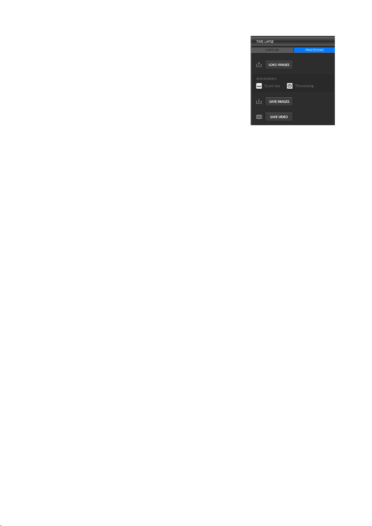
Process images
Select the PROCESSING tab in the TIME LAPSE control
panel to add annotations to or create a slideshow video
of time lapse images.
To add annotations:
1. Load previously captured images by clicking LOAD
IMAGES or use just captured images.
2. Add a scale bar or timestamp as needed. Right click
on an annotation to change properties such as color
and size.
3. To save annotated images, click SAVE IMAGES.
To create a slideshow video file of time lapse images:
1. Click SAVE VIDEO.
2. Enter the file name and select the file path.
3. Select the frame rate, resolution, and quality of the video.
4. Click OK.
Important! Any annotations onscreen will carry over to the video. You do not need to
save annotated images to create a video file with annotations – what you see
onscreen will be applied to the video.
14

Cell Counting
CELL COUNTER mode provides the option to count cells automatically or manually. Both
reusable and disposable slides from Logos Biosystems can be used for cell counting.
AUTOMATED CELL COUNTER
Automated cell counter
control panel
Select the AUTOMATED tab in the CELL COUNTER
control panel.
For automated cell counting, set the CELENA® S with the
following settings:
Iris diaphragm: Move to Δ (2 cm from the right)
Phase annuli: BF
Filter cube: Trans
Objective: 4X
Gain: 0 dB
Exposure: 10 ms
Click Protocol to set specific parameters for automated cell counting. The current set protocol is
shown to the right of the button.
Select Autofocused counting for the instrument to fine focus on the cells during counting.
Select Auto exposure for the instrument to adjust light settings automatically during counting.
Protocol parameters and
settings
Parameter
Range
DEFAULT protocol
Dilution Factor
1-100
2
Live Cell Sensitivity
1-9
4
Roundness (%)
0-100
10
Min. Cell Size (µm)
1-59
5
Max. Cell Size (µm)
2-60
60
Dilution Factor: The dilution factor is used to calculate cell concentrations. Assuming a 1:1
ratio of stain to cell suspension, the DEFAULT dilution factor is preset to 2. Adjust this value
according to the dilution of the cell sample.
Live Cell Sensitivity: Live cells with intact cell membranes exclude dyes like trypan blue and
Erythrosin B. The dyes form halos around live cells and stain the cytoplasm of dead cells or
cells with compromised membranes. With a higher live cell sensitivity, the instrument can
detect smaller cells by registering smaller halos.
Roundness: Cells are not all completely spherical. Adjusting the roundness to detect cells of
various shapes. Higher values lead to the counting of rounder cells and excludes objects with
less roundness. Lower values are suitable for counting cells with irregular shapes.
Cell Size: Users can customize cell size parameters to detect specific cells efficiently. Values
can be adjusted in 1 µm increments for sizes between 3-60 µm.
The DEFAULT protocol cannot be modified or deleted.
To create a new protocol, select New Protocol. Click Edit to modify the selected protocol. This
will activate the arrows for each parameter, turning them a solid grey. Use the arrows to adjust
the values of each parameter as desired. Click Save as and use the onscreen keyboard to name
the protocol. The newly created protocol will appear in the list of protocols.
To delete a selected protocol, click Delete to delete the selected protocol.
To load a specific protocol, select the desired protocol and press Save & Load.
Important! Merely selecting a protocol does not mean that it has been put into effect.
To apply the selected protocol, make sure to click Save & Load.
15

Counting cells in
automated cell counting
mode
1. Click LIVE.
2. Set the iris diaphragm, phase annuli, objective, filter cube, gain, and exposure as indicated in
the Prequisite Settings.
3. Load a protocol.
4. Prepare a stained cell sample according to standard procedures.
5. Load 10-12 µL of the cell sample into a new LUNA
™
Cell Counting Slide or a clean LUNA™
Reusable Slide. Place into an appropriate vessel holder.
Important! The automated cell counter algorithm is compatible with LUNA™ Cell
Counting Slides, PhotonSlides™ or LUNA™ Reusable Slides from Logos Biosystems.
6. Focus in on the cell sample. Even with Autofocused Counting selected, the cells should be
visible to ensure accurate focusing and counting. Adjust the light settings as needed or
select Autoexposure.
7. Click COUNT.
8. The results will appear in the CELL COUNTER control panel.
View/save results
Results
Cell count results will appear in the CELL COUNTER
control panel.
Live cells will be labeled with green circles and dead
cells with red circles. Click Tag to remove the labels.
To calculate dilutions, click Dilution Calculator. Set the
current concentration as the total, live, dead, or a
custom cell concentration by clicking the box below the
Current Concentration value. Enter values for the
desired final concentration and volume. Click Load.
Histogram
Below the numerical data, a cell size distribution
histogram will appear.
Click cell concentration in the y-axis to switch it to cell
number.
Use the button below to toggle between the total, live,
and dead concentrations.
Click cluster map to show the percentage of single cells,
doublets, and triplets.
Save
To save the raw image, tagged, image, and data in csv format, click SAVE.
16

MANUAL CELL COUNTER
Manual cell counting
Select the MANUAL tab in the CELL COUNTER control
panel.
1. Click LIVE.
2. Set the diaphragm, phase annuli, objective, filter
cube, light, and focus as needed.
3. Place a sample into the appropriate vessel holder.
4. Click CAPTURE.
5. To tag, left-click on the image. As you tag each item, the system keeps a running tally of the
counts. To delete tags, right-click on the image.
To save the raw and/or tagged image, click SAVE.
Saving Images
FILE MANAGER
File Manager
Captured images can be saved in monochrome or with pseudocolor as TIF, JPG, BMP, or PNG
(12-bit dynamic range) on the instrument or an external drive.
Saved images can be further organized by selecting the FILE MANAGER option in the menu bar.
Images can be previewed onboard but video and csv files cannot. Click the tile icon next to the
command buttons at the top to view images as thumbnails.
Use the command buttons at the top to create new folders or copy, paste, delete, or cut files.
Alternatively, right-click on icons to bring up commands.
To eject an external drive, select the drive you want to remove and click Eject USB at the bottom
of the screen.
Back up and/or transfer files from the onboard SSD periodically. Logos Biosystems does not
warrant the data stored in the SSD and will not be held liable for damages associated with data
restoration.
17

Settings
Settings
Click the Settings button in the menu bar. The current version of software and the
instrument’s serial number is recorded here.
Software update
Download the most recent version of software from the Logos Biosystems website
(www.logosbio.com) into the root directory of a USB drive. Insert the USB drive to a USB port
in the instrument. Click S/W Update. Do not turn the instrument off during the update.
Error report
(Maintenance use only) To create an error report, connect a USB drive to a USB port in the
instrument. Click Error Report. Do not turn the instrument off during the process.
Settings control panel
FILTER CUBES
After installing LED filter cubes, enter the name of and desired pseudocolor for each LED filter
cube in its respective location.
OBJECTIVES
After installing objectives, enter the magnification, numberical aperature, brand, and a note
for each objective in its respective location.
FOCUS
Choose to correlate the left and right focus knobs with coarse or fine focusing. Adjust the
focusing speed and distance moved with each manipulation. The Fine AF scan range can also
be changed. Click CLEAR to erase set focus memory positions. Click RESET to return to factory
settings.
CAMERA MODE
Choose to capture images with a pixel depth of 8 or 16 bit (12 bit dynamic range). There are
options to highlight saturated pixels in red or to enable hot pixel correction.
TIME/DATE
Adjust the instrument’s date and time.
MISCELLANEOUS
Choose to show or hide the welcome message at startup. The welcome message contains a
reminder that the Z-stage is docked for safety when the system is shut down. The end user
licence agreement may also be viewed here.
CAPTURE
Modify the default annotation line color or width. The default font size and color can also be
adjusted. Click Enable Quick Save mode to save images without having to determine save
options each time. Designate the default file path for quick saved images.
Z-STACK
Modify the preset lag time of the Z-stage during Z-stack imaging.
18
Maintenance
Routine care
Clean surfaces with a soft cloth dampened with distilled water or 70% ethanol. Immediately wipe
dry with a clean cloth. Do not pour or spray liquids directly onto the instrument. To avoid electrical
shock or damage, do not wet electrical wires or connections. If liquid is spilled on the instrument,
turn off the power and wipe dry immediately.
Use only optical-grade cleaning materials to clean optical components.
Do not exchange components between instruments unless they have been provided or authorized
by Logos Biosystems.
Installation and
removal of
components
Objectives
1. Turn the instrument off and remove the insert plate from the stage.
2. Grasp the objective at its base and unscrew it from the turret.
3. Replace it with the desired objective and screw it in securely.
4. Reinstall the insert plate.
5. Turn on the instrument and change the objective lens information in the Settings.
Calibrate parfocality if needed.
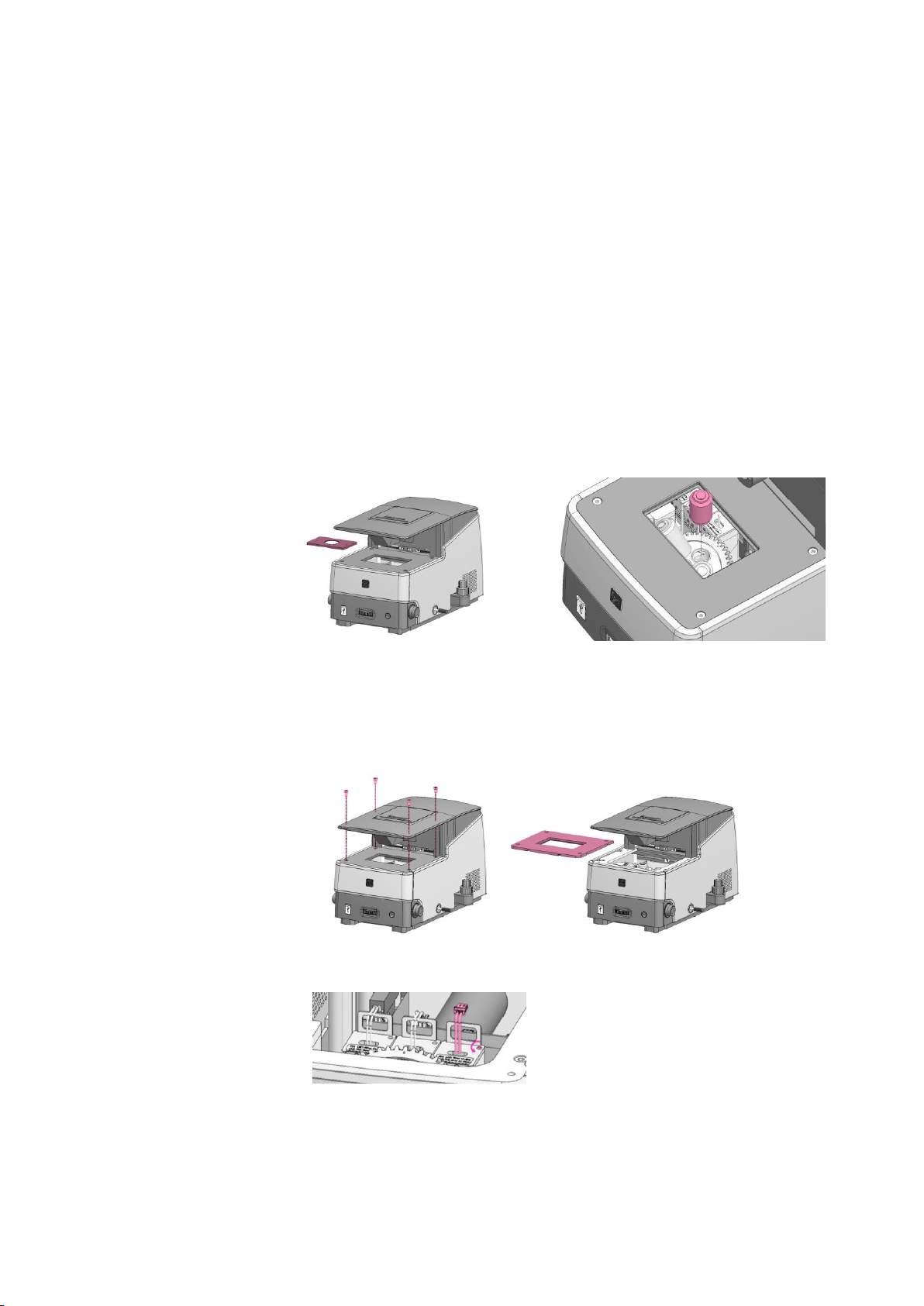
LED Filter Cubes
1. Turn the instrument off and remove the insert plate from the stage.
2. Unscrew the screws from the four corners of the stage with a hex wrench from the tool kit.
Remove the stage.
3. Unplug the connector of the LED filter cube. Loosen the screw in the cube with the flat-head
screwdriver from the tool kit. Pull out the LED filter cube.
4. Insert the desired LED filter cube, fasten its screw, and plug in its connector.
5. Reinstall the stage and insert plate.
6. Turn the instrument on and change the LED filter cube information in the Settings.
19

Troubleshooting
Image quality
Misaligned overlay image
Recapture images in each channel. Do not touch the stage or focusing knobs while capturing.
Dim transmitted light image
Check that the iris diaphragm and phase annuli are in the appropriate positions.
Dim transmitted light image with TC PlanFluor objectives
Set the phase annuli slider to the BF position. TC PlanFluor objectives do not have phase rings.
Uneven focus
Place the sample flat on the stage. Make sure the sample thickness is uniform.
Trouble focusing on a coverslipped sample with TC PlanAchro or TC PlanFluor objectives
Place the slide with the coverslip facing up.
Trouble focusing on a coverslipped sample with Plan Apochromat objective
Place the slide with the coverslip facing down.
Black screen after clicking LIVE
1. Click the ON button in the LIGHT panel.
2. Ensure that the objective turret has clicked into position.
3. Ensure that the phase annuli slider is in the proper position.
4. Center the sample over the objective.
Software
Image irresponsive to changes in focus or stage position
Click the ON button in the LIGHT panel.
Inactive ON/OFF switch in LIGHT panel
Verify that the filter cube selection tail and the objective turret have clicked into position.
Inactive SAVE button
Capture the image first. The SAVE button is only active after an image has been captured.
Mechanical
No place for sample on vessel holder frame
Use the appropriate vessel holder.
Data saving/transfer
Too many files on SSD
Image acquisition and analysis may become slower when there are too many files saved on the
SSD. Delete or move files to an external drive.
Incompatible USB
Some USB drives are undetectable or incompatible. Use the USB supplied with the instrument or
make sure that your USB is compatible with the instrument. The USB must be Ver 2.0.
Software update
Incompatible USB
Some USB drives are undetectable or incompatible. Use the USB supplied with the instrument or
make sure that your USB is compatible with the instrument. The USB must be Ver 2.0.
More than one software version on the USB
Delete previous versions of software from the USB before downloading new software.
Incorrectly saved or damaged software
1. Use the USB supplied with the instrument or make sure that your USB is compatible with the
instrument.
2. Download the file again into the root directory of the USB drive.
3. Insert the USB drive properly.
4. Click the S/W Update button again. If the problem persists, contact your local sales
representative.
20

Safety Information
Instrument safety
General safety
Operate the instrument in the conditions described in the Operating Conditions.
Install the instrument on a level and sturdy surface. Avoid vibrations from other devices. The
instrument can withstand light shock and vibration. However, excessive shock and/or vibration
may damage the instrument. Leave sufficient space around the instrument for air circulation
and cooling. Take care that the instrument does not overheat during long and continuous
operation.
Do not touch the instrument or its components with wet hands.
Use components provided or authorized by Logos Biosystems. If the proper combination of
components is not used, product safety cannot be guaranteed.
Use only the provided power cord and AC adapter. If the proper components are not used,
electrical safety of the product cannot be guaranteed.
Ensure that the input voltage is compatible with the power supply voltage of the product.
Connect the grounding terminal of the instrument and electrical outlet properly. If the
instrument is not grounded, electrical safety of the product cannot be guaranteed.
Turn on the instrument only after connecting the power cord and AC adapter to both the power
source and the instrument. Turn off the instrument before disconnecting the power cord and/or
moving the instrument.
Do not expose the instrument to intense ultraviolet light.
This instrument uses Class 3B ultraviolet LEDs that are in accordance with IEC/EN 60825-1.
Always turn the instrument off before changing LED filter cubes.
Turn off the power using the power button within the software. Use the power button at the
front of the instrument to turn off the power in the case of an emergency or a system error.
Disconnect the power cord in the case of abnormalities.
Protect USB drives from being infected with viruses and malware.
Operating conditions
Operating Power
100 - 240 VAC, 1.5 A
Electrical Input
12 VDC, 5.0 A
Frequency
50/60 Hz
Installation Site
Indoor use only
Operating Temperature
10 - 35°C
Maximum Relative Humidity
20 - 80%
Altitude
≤ 2,000 m
Pollution Degree
2
Instrument disassembly
Do not disassemble the instrument in any event as this will invalidate your warranty. If the
instrument is damaged or malfunctioning, contact your local sales representative.
21

Personal safety
Safety guidelines
Read all user manuals thoroughly before using the instrument.
Keep all user manuals in a safe and accessible place for future reference.
Wear appropriate personal protective equipment (PPE) when handling reagents and samples to
avoid exposure.
When using toxic agents, radioactive materials, or pathogenic microorganisms belonging to
WHO Risk Groups 2-4, follow national laws and regulations for biosafety level requirements.
Instrument symbols
Electrical symbols
Symbol
Description
Power symbol
Protective earth (ground) terminal
Safety symbol
Symbol
Description
WARNING! UV radiation hazard. Avoid looking directly at UV light.
Environmental symbol
Symbol
Description
Waste Electrical and Electronic Equipment (WEEE). Do not dispose of this product as
unsorted municipal waste. Follow local waste ordinances for proper disposal provisions
to reduce the environmental impact of WEEE.
Safety standards
European standards
Symbol
Description
The CE mark indicates that this instrument conforms to all applicable European
Community provisions for which this marking is required. Users must be aware of and
follow the conditions described in this manual for operating the instrument. The
protection provided by the instrument may be impaired if the instrument is used in a
manner not specified by Logos Biosystems.
Korean standards
Symbol
Description
The KC certification mark indicates that this instrument conforms with Korea’s product
safety requirements for electrical and electronic equipment and components for which
this marking is required.
United States standards
Type
Description
FCC
Part 18
This device complies with Part 18 of the FCC Rules.
22

Product Specifications
CELENA® S Digital Imaging System
Physical characteristics
Instrument type
Benchtop digital epifluorescence and transmitted light imaging system
LCD display
Full HD color LCD monitor, 1920 x 1080 pixels (not included)
Dimensions
44 cm x 30 cm x 27 cm (17.3 in x 11.6 in x 10.6 in)
Weight
20 kg (44 lb)
Technical specifications
Imaging methods
Epifluorescence and transmitted light (brightfield and phase contrast)
Illumination
LED filter cubes with adjustable intensity (>50,000 hr life per filter cube)
Fluorescence channels
3 fluorescence channels and 1 transmitted light channel
Objective turret
5 positions
Objectives
High quality long working distance (LWD) and coverslip-corrected; 1.25X-100X
Condenser
47 mm LWD condenser; 3-positions with brightfield and phase contrast annuli
Stage
Mechanical X/Y stage, motorized Z stage; accommodates an onstage incubator
Computer
Built-in dual core CPU, 128 GB SSD internal storage
Camera
1.3 MP monochrome CMOS with 1280 x 1024 pixels
Images
8 or 16-bit TIFF, JPG, BMP, or PNG
Onstage Incubation System
Physical characteristics
Compatible vessels
35 mm dishes, microslides
Dimensions
Heated plate with lid: 15.5 cm x 23.6 cm x 3.0 cm
Temperature controller: 23 cm x 17 cm x 9 cm
Gas mixer: 23 cm x 17 cm x 9 cm
Weight
Heated plate with lid: 0.4 kg (0.9 lb)
Temperature controller: 3.4 kg (7.5 lb)
Gas mixer: 2.1 kg (4.6 lb)
Technical specifications
Temperature range
Ambient temperature to 55°C
CO2 range
0.1-20%
O2 range
0-21%
Humidity range
22-99%
23

Ordering Information
Instruments
Cat #
Product
Quantity
CS20001
CELENA® S Digital Imaging System
1 set
CS20002
CELENA® S Digital Imaging System Starter Kit
1 set
- TC PlanAchro 4X Ph
- TC PlanFluor 10X
- TC PlanFluor 20X
- TC PlanFluor 40X
- DAPI
- EGFP
- RFP
Onstage incubation systems
Cat #
Product
Quantity
I10401
Universal Heating System
1 set
I10402
Gas Incubation System for CO2
1 set
I10403
Gas Incubation System for CO2/O2
1 set
I10410
Heating Insert for Micro Slides
1 unit
I10411
Heating Insert for a 35 mm Dish
1 unit
Objectives
Cat #
Product
Quantity
I10001
TC PlanAchro 4X Ph
1 unit
I10002
TC PlanAchro 10X Ph
1 unit
I10003
TC PlanAchro 20X Ph
1 unit
I10004
TC PlanAchro 40X Ph
1 unit
I10005
TC PlanFluor 4X
1 unit
I10006
TC PlanFluor 10X
1 unit
I10007
TC PlanFluor 20X
1 unit
I10008
TC PlanFluor 40X
1 unit
I10013
Plan Apochromat Fluor 1.25X
1 unit
I10014
Plan Apochromat Fluor 4X
1 unit
I10009
Plan Apochromat Fluor 10X
1 unit
I10010
Plan Apochromat Fluor 20X
1 unit
I10011
Plan Apochromat Fluor 40X
1 unit
I10015
Plan Apochromat Fluor Oil 40X
1 unit
I10012
Plan Apochromat Fluor Oil 100X
1 unit
LED filter cubes
Cat #
Product
Quantity
I10101
DAPI
1 unit
I10102
EGFP
1 unit
I10103
RFP
1 unit
I10104
mCherry
1 unit
I10105
ECFP
1 unit
I10106
EYFP
1 unit
I10107
DSRed
1 unit
I10108
Cy5
1 unit
I10109
Cy7
1 unit
I10110
Cy3/TRITC Long Pass
1 unit
I10111
GFP Long Pass
1 unit
I10112
Cy5 Long Pass
1 unit
I10113
Custom Filters
1 unit
24

Vessel holders
Cat #
Product
Quantity
I10201
Universal Holder
1 unit
I10202
25 mm x 75 mm Slide Holder, Two Positions
1 unit
I10203
35 mm Cell Culture Dish Holder, Four Positions
1 unit
I10204
60 mm Cell Culture Dish Holder, Two Positions
1 unit
I10205
100 mm Cell Culture Dish Holder, One Position
1 unit
I10206
25 cm2 Nunc T-25 Flask Holder, Two Positions
1 unit
I10207
75 cm2 Nunc T-75 Flask Holder, One Position
1 unit
I10208
25 cm2 BD/Greiner T-25 Flask Holder, Two Positions
1 unit
I10209
75 cm2 BD/Greiner T-75 Flask Holder, One Position
1 unit
I10210
Glass Hemocytometer Holder, One Position
1 unit
Counting slides
Cat #
Product
Quantity
L12001
LUNA™ Cell Counting Slides, 50 Slides
1 box
L12002
LUNA™ Cell Counting Slides, 500 Slides
10 boxes
L12003
LUNA™ Cell Counting Slides, 1000 Slides
20 boxes
L12005
PhotonSlide™, 50 Slides
1 box
L12006
PhotonSlide™, 500 Slides
10 boxes
L12007
PhotonSlide™, 1000 Slides
20 boxes
L12008
LUNA™ Reusable Slide
1 unit
25

Purchaser Notification
Limited use label license
Research use only
The purchaser of this product should use this product only for research for the sole benefit of the purchaser. By
use of this product, the purchaser agrees to be bounded by the terms of this limited use statemen t whether the
purchaser is a for-profit or a not-for-profit entity.
If the purchaser is not willing to accept the conditions of this limited use statement and this product is unused,
the Company will accept return of the product with a full refund.
The purchaser cannot resell or otherwise transfer (a) this product (b) its components or (c) materials made using
this product or its components to a third party for Commercial Purposes.
Commercial Purposes mean any and all uses of this product and its components by a party for monetary or other
consideration, including but not limited to, (a) product manufacture, (b) providing a service, information, or data,
(c) therapeutic, diagnostic, or prophylactic purposes, or (d) resale of this product or its components wh ether or
not such product and its components are resold for use in research.
Logos Biosystems, Inc. (“Company”) will not claim any consideration against the purchaser of infringement of
patents owned or controlled by the Company which cover the product based on the manufacture, use or sale of a
therapeutic, clinical diagnostic, vaccine, or prophylactic product developed in research by the purchaser in which
this product or its components was employed, provided that neither this product nor any of its compon ents was
used in the manufacture of such product.
For any use other than this limited use label license of research use only, please contact the Company or email
info@logosbio.com for more information.
LTC licensed products
LED filter cubes
LED Filter Cubes are LTC Licensed Products provided under an intellectual property license from Life Technologies
Corporation. The transfer of this product is conditioned on the buyer using the purchased product solely in
research conducted by the buyer, and the buyer must not (1) use this product or its components for (a)
diagnostic, therapeutic or prophylactic purposes; or (b) manufacturing, and/or (2) sell or transfer this product or
its components for resale, whether or not resold for use in research. For information on purchasing a license to
this product for purposes other than as described above, contact Life Technologies Corporation, 5791 Van Allen
Way, Carlsbad, CA 92008 USA or outlicensing@lifetech.com
Instrument warranty
Warranty
Logos Biosystems, Inc. (“Company”) warrants to the original purchaser (“Purchaser”) that the instrument
(“Instrument”), if properly used and installed, will be free from defects in materials and workmanship and will
conform to the product specifications for a period of one (1) year (“Warranty Period”) from the date of purchase.
If the Instrument under this limited warranty fails during the Warranty Period, the Company, at its sole
responsibility, will: within and up to 30 calendar days of purchase, refund the purchase price of the Instrument to
the Purchaser if the Instrument is in original conditions; or, after 30 calendar days of purchase, only replace or
repair the Instrument for up to the Warranty Period without issuing a credit.
In no event shall the Company accept any returned instrument (including its components) that might have been
used or contaminated in some labs, including but not limited to, HIV or other infectious disease or blood -handling
labs. This limited warranty does not cover refund, replacement, and repair incurred by accident, abuse, misuse,
neglect, unauthorized repair, or modification of the Instrument. This limited warranty will be invalid if the
Instrument is disassembled or repaired by the Purchaser.
In case that the Company decides to repair the Instrument, not to replace, this limited warranty includes
replacement parts and labor for the Instrument. This limited warranty does not include shipment of the
Instrument to and from service location or travel cost of service engineer, the costs of which shall be borne by the
Purchaser. Every effort has been made to ensure that all the information contained in this document is correct at
its publication. However, the Company makes no warranty of any kind regarding the contents of any publications
or documentation as unintended or unexpected errors including occasional typographies or other kinds are
inevitable. In addition, the Company reserves the right to make any changes necessary without notice as part of
ongoing product development. If you discover an error in any of our publications, please report it to your local
supplier or the Company. The Company shall have no responsibility or liability for any special, incidental, indirect
or consequential loss or damage resulting from the use or malfunction of the Instrument.
This limited warranty is sole and exclusive. The Company makes no other representations or warranties of any
kind, either express or implied, including for merchantability or fitness for a particular purpose with regards to
this Instrument. To obtain service during the Warranty Period, contact your local supplier or the Company’s
Technical Support team.
Out of warranty service
Please contact your local supplier or the Company’s technical support team in order to obtain out-of-warranty
service. If necessary, repair service will be charged for replacement parts and labor hours incurred to repair the
Instrument. In addition, the Purchaser is responsible for the cost of shipping the Instrument to and from the
service facility and, if necessary, the travel cost of a service engineer after 30 calendar days of purchase, only
replace or repair the Instrument for up to the Warranty Period without issuing a credit.
26

Logos Biosystems
HEADQUARTERS
FL 2 & 3
28 Simindaero 327beon-gil, Dongan-gu
Anyang-si, Gyeonggi-do 14055
SOUTH KOREA
Tel: +82 31 478 4185
Fax: +82 31 478 4184
Email: sales@logosbio.com
USA
7700 Little River Turnpike STE 207
Annandale, VA 22003
USA
Tel: +1 703 622 4660
Tel: +1 703 942 8867
Fax: +1 517 266 3925
Email: sales@logosbio.com
EUROPE
11B avenue de l’Harmonie
59650 Villeneuve d’Ascq
FRANCE
Tel: +33 (0)3 74 09 44 35
Fax: +33 (0)3 59 35 01 98
Email: info-france@logosbio.com
www.logosbio.com
 Loading...