


REEL ROTATOR
ELFRRM / ELFSRRM, ELFRRE / ELFSRRE

EU DECLARATION CONFORMANCE
Manufacturer: Logitrans A/S
Hillerupvej 35
DK-6760 Ribe
Denmark
It is hereby declared that:
Machine: Productgroup: Reel Rotator
Type: ELFRRE / ELFSRRE
Year of manufacture/
Serial No:
a) Has been manufactured in conformance with the stipulations of the:
• Directive no. 2006/42/EC
• Directive no. 2004/108/EC
• Directive no. 2006/95/EC
ELFRRM / ELFSRRM
b) Has been manufactured in conformance with the stipulations of the standard:
• EN 3691-5
Name: Gitte K. Berg
Position: CEO
Company: Logitrans A/S
Product type declaration of:
Signature:
Distributor:
16.02.2016
D179-1

Contents
1.0 Before the first lift... ............................................................................................. 4
2.0 Functions and identifications .......................................................................... 5
3.0 How to operate the Reel Rotator ................................................................... 7
3.1 Handling of reels.................................................................................................................. 7
3.2 Use of the Reel Rotator ....................................................................................................... 7
3.3 Clamping of reels................................................................................................................. 8
3.4 Extra support ..................................................................................................................... 10
3.5 Manual rotation (ELFRRM/ELFSRRM) ..............................................................................11
3.6 Electric rotation (ELFRRE/ELFSRRE)............................................................................... 12
3.7 Adjusting of rotation stop (ELFRRE/ELFSRRE) ................................................................ 13
3.8 Setting the speed (ELFRRE/ELFSRRE) ........................................................................... 13
3.9 Reset (ELFRRRE/ELFSRRE) ........................................................................................... 13
4.0 Optimum safety ..........................................................................................14
4.1 Rotation range ................................................................................................................... 14
4.2 Safety regulations .............................................................................................................. 15
4.3 Driving loaded.................................................................................................................... 16
4.3 Rotation range ................................................................................................................... 16
4.4 Rotation with load .............................................................................................................. 16
4.5 Emergency braking and Emergency stop.......................................................................... 16
5.0 There must be a current supply... ................................................................17
5.1 Fuses - replacement .......................................................................................................... 17
5.2 Wiring connections ............................................................................................................ 17
6.0 Long live Reel Rotator ........................................................................................ 18
6.1 Lubrication and hydraulic oil .............................................................................................. 18
6.2 Oil change ......................................................................................................................... 18
6.3 Adjustment of reel carriage ................................................................................................ 19
6.4 Adjustment of lifting chain .................................................................................................. 19
6.5 Adjustment of steering wheel chains ................................................................................. 20
6.6 The hydraulic pump and gear motor .................................................................................. 20
6.7 Cleaning ............................................................................................................................ 20
6.8 Adjustment of side play...................................................................................................... 21
7.0 Adjusting the Reel Rotator .............................................................................. 22
7.1 Tensioning the chains ........................................................................................................ 22
7.2 Adjusting the switch ........................................................................................................... 23
7.3 Lubrication ......................................................................................................................... 23
8.0 Fault location key ................................................................................................. 24
9.0 Good service after purchase ......................................................................... 26
9.1 Ordering spare parts.......................................................................................................... 26
9.2 Warranty/Compensation .................................................................................................... 26
9.3 Service and repair ............................................................................................................. 26
9.4 Warranty ............................................................................................................................ 26
9.5 Liability exemption ............................................................................................................. 26
3

1.0 Before the first lift...
The Reel Rotator is manufactured in accordance with safety directives.
Among the subjects dealt with in this Instruction Manual are:
- Proper application
- Physical limitations of the product
- Risks with improper use
- Therefore please read this Instruction Manual carefully!
4

2.0 Functions and identifications
Released position
Lifting/Lowering
Emergency stop
To release the brake:
1. Pull
2. Push
Braked position
Instrument board
- Battery indicator
- Type plate
- Charging plug
(internal or external charger)
- Plug for extra equipment,
12V maximum 20 Amp
5

2.0 Functions and indentifications
Clockwise/
counterclockwise
Remote control for rotation (ELFRRE/ELFSRRE)
The remote control is used when:
• Rotating the reel carriage
• Setting tilt stop in both directions: See paragraph 3.7.
• Setting rotation speed: See paragraph 3.8.
Remote control for clamping (all models)
The remote control is used when:
• Clamping/fastening
• Opening/releasing
6

3.0 How to operate Reel Rotator
3.1 Handling of reels
ELFSRRM & ELFSRRE
Handling of reels on closed pallets
- Use the Reel Rotator with straddle legs!
ELFRRM & ELFRRE
3.2 Use of the Reel Rotator (ELFRRE/ELFSRRE)
Conditions for rotation: Center of the gripping arms is lifted at least:
ELFRRE: 825 mm
ELFSRRE: 750 mm
ELFRRE/ELFSRRE:
side
.
Note: The rotation stops automatically, when the gripping arms are placed
horizontally/in position 0°.
To continue the rotation function from 0°, the rotation switch has
to be released and activated again in the requested rotation direction.
To lower the reel carriage fully, the reel carriage has to be placed in position 0°.
Soft acceleration / deceleration
The Reel Rotator has soft acceleration / deceleration with the following benets:
The load can be rotated 355º with one adjustable stop in every
• The reel rotation stops precisely.
• The gear is protected, because sudden start / stop are minimised.
7

3.0 How to operate the Reel Rotator
3.3 Clamping of reels
3
8

3.0 How to operate the Reel Rotator
Clamping:
(o)
Press until the lamp lightens
green.
When red lamp lightens, the
clamping force is not sufficient.
Releasing:
(o)
Press both buttons at the same
time to open the gripping arms.
Note: As a safety precaution,
the gripping arms can only be
opened, when the lifting system
is without pressure.
9

3.0 How to operate the Reel Rotator
3.4 Extra support
For reels from Ø800mm to Ø1270mm it is possible to use three-points clamping.
By adjusting the shown supporting plate, so that it supports the reel, it can be
prevented that the reel moves between the two plates that primarily fasten the reel.
The supporting plate can also be set as stop for a certain reel diameter.
Supporting plate
10

3.0 How to operate the Reel Rotator3.0 How to operate the Reel Rotator
3.5 Manual rotation (ELFRRM/ELFSRRM)
ATTENTION
Check that the load is placed in the load center before rotating.
Press the handle to position
”Release”
The reel carriage can now
be rotated by the gripping
handle.
Note: The reel carriage can be locked for each 90°.
Conditions for rotation: Center of the gripping arms is lifted at least:
ELFRRM: 825 mm
ELFSRRM: 750 mm
11

3.0 How to operate the Reel Rotator
3.6 Electric rotation (ELFRRE/ELFSRRE)
ATTENTION
Check that the load is placed in the load center before rotating.
Use the remote control for the rotation:
A
B
Press “A” to rotate clockwise (seen from position behind the
handle).
Press “B” to rotate counterclockwise (seen from position behind
the handle).
From the factory the rotation is preset to stop 90° to each side.
The load can as maximum be rotated 355º with one adjustable
stop in every side.
Note: The load has to be placed in position 0°, before the load
can be lowered fully.
12
3.0 How to operate the Reel Rotator
3.7 Adjusting of rotation stop (ELFRRE/ELFSRRE)
The reel carriage is factory-set to stop in 90º. If another setting is required, it can be
set electronically to stop in different angles.
1) The reel carriage is placed in position 0°.
2) Short pressure on the switch A activates the setting
procedure. The controller gives a signal (one beep).
3) The reel carriage is placed in the requested angle.
4) When the reel carriage has reached the requested
angle, the controller will give signal after three
seconds (one beep), when the position has been
stored.
The procedure is repeated to set the stop in the other
side.
A
3.8 Setting the speed (ELFRRE/ELFSRRE)
1) The reel carriage is placed in position 0°.
2) The switch (A) is pressed three seconds, and two
short beeps will be given. The switch is released
and the speed is set by activating the remote
control.
Plug from
remote control
Clockwise: Increasing the speed
Counter-clockwise: Reducing the speed
Note: Maximum rotation speed (0-355º): 30 sec.
3) 3 seconds after releasing the switch on the remote
control, the controller will give signal (two beeps),
indicating that the requested speed has been
stored.
Switch A
Signal
3.9 Reset the settings (ELFRRE/ELFSRRE)
1) The reel carriage is placed in position 0°.
2) Press switch (A), until ve beeps are given. The switch is released and the
controller is set to maximum speed and stops at 45°.
13

4.0 Optimum safety
4.3 Rotation range
Standard version
The load can be rotated, when the turning point of the reel carriage is raised more
than 750 mm (ELFSRRM/ELFSRRE) and more than 825 mm (ELFRRM/ELFRRE).
Below this range, it is only possible to raise/lower the reel carriage in position 0°.
Bottom stop (ELFRRE/ELFSRRE)
Adjusted with the following turning point above
the floor:
ELFSRRE: 750 mm
ELFRRE: 825 mm
14

4.0 Optimum safety
4.2 Safety regulations
• Never walk under a raised load!
• Never stand between the gripping arms!
ATTENTION
Moving parts
• Before lowering the reel carriage, make certain that no foreign
elements can hinder the free lowering of the reel carriage
• The Reel Rotator is designed for use on an even
and level oor
• During transport the reel carriage shall be raised as little as possible
• Transport with raised reel carriage should be made over the shortest
possible distances and at low speed
• Check that the chains lift equally. They shall be equally tight when the reel
carriage is loaded
• Chains and chain bolts must not be damaged. Chains that have become
permanently stretched (max. 2 % of original length) must be scrapped.
15

5
4.0 Optimum safety
4.3 Driving loaded
The Reel Rotator is designed for use on even and level oor. During transport the
reel carriage shall be raised as little as possible. Transport with raised reel carriage
should be made over the shortest possible distances and at low speed.
4.4 Rotation with load
NOTE! Rotation is only allowed to take place, if the Reel Rotater is placed on an
equal oor.
When rotating reels, the operator needs a full
overview of the whole working area, so that the
rotation movement can be stopped before the
reel touches the oor, the items or persons in the
working area.
4.5 Emergency braking and Emergency stop
The Reel Rotator has an emergency stop. When activating the
emergency stop, the main current supply is switched off.
The movement of the reel carriage stops immediately when
activating the emergency stop.
16

5.0 There must be a current supply...
5.1 Fuses - replacement
There are five fuses in the electrical circuit:
100 Amp fuse in the main supply from battery
10 Amp fuse in the control current circuit
20 Amp fuse (plug for extra equipment on the instrument board)
20 Amp fuse for built-in charger
40 Amp fuse for rotation
40A
10A 20A 20A
Replacement:
The old fuse is to be removed and replaced by a new one of the same size.
Find out why the fuses blow!
100A
5.2 Wirring connections
Many operational disturbances are caused by bad
connections in the elctrical circuit. Make sure that the
connections are in order.
Check connections regularly for damage at insulating caps or
bad connections at plugs etc. Verdigris must be removed from
cable plugs. Keep all screw/nut connections tight.
17

6.0 Long live Reel Rotator
Regular inspection and the replacement of worn or defective parts in good time will
prolong the life of the Reel Rotator. “Prevention is better than repair”, therefore ensure:
• That the battery is fully charged every time
• Correct usage
• Regular cleaning
• Periodic safety and service inspection
• For safety reasons please check the below every 3 month:
- Tighten loose screw and nuts
- Check that there are no cracks, fractures and deformations in
the bearing construction
- Wearing parts, such as brakes, wheels and bearings, are adjusted and
exchanged continuously
6.1 Lubrication and hydraulic oil
Under normal operation conditions the Reel Rotator requires no
lubrication. All ball bearings are sealed and lubricated for life, and
moving parts have self-lubricating bearings or are treated with grease.
The hydraulic system is lled with hydraulic oil of viscosity class
ISO VG 15. An additive is added to the oil. The concentrate reduces friction and wear
and protects against corrosion. Pre-mixed hydraulic oil with additive is available from
the dealer. The oil is suitable for use in the temperature range -10 to +50° C. A thinner
oil is recommended for temperatures lower than -10° C (if necessary, contact your
dealer).
6.2 Oil change
Draining the oil:
1. Bring the unloaded reel carriage down to the lowest position.
2. Most of the oil can be drained by loosening the hydraulic hose union and briey
activating the hydraulic pump with the switch.
3. The remaining oil can be drained from the oil tank by removing the tank.
Oil lling:
4. Fill oil through the lling hole on the tank.
5. Oil quantity: ELFRRM 1750 & ELFSRRM 1750 approx 3 liter
ELFRRE 1750 & ELFSRRE 1750 approx 3 liter
6. Ret the lling cap and bleed the system (6.6).
18

6.0 Longe live Reel Rotator
6.3 Reel carriage adjustment
Two of the rollers on the reel carriage are
mounted on eccentric pins, so that they can be
adjusted. The adjustable rollers are at the top.
1. Loosen screw (pos. 91) (key width 5 mm).
2. Eccentric pins (pos. 56) (key width 8 mm)
can now be turned to give the necessary
reel carriage adjustment.
3. Adjustment must be made on both sides
to ensure uniform loading of the rollers.
6.4 Adjustment of lifting chain
The chains shall be adjusted so that
• they lift equally
• they are equally tight
• The lifting movement has to stop in the cylinder,
before the mast rolls touch the top stop.
The nuts (pos. 18) are to be adjusted
(nut M12, key width 19 mm).
18
19

6.0 Longe live Reel Rotator
6.5 Adjustment of steering wheel
chains
- Set the handle in its middle position.
- Adjust the nuts (1, 2, 3 and 4) and bring
the wheels into parallel.
6.6 The hydraulic pump and the gear motor
The hydraulic pump has a S3 “periodic intermittent duty” of 10%. This means that
the pump in total is allowed to operate 1 minute for a period of 10 minutes.
Note! If the pump operates more than 10%, the motor will be damaged due to
superheating.
Bleeding the hydraulic system
With a load of 50-100 kg, the reel carriage must be raised and lowered to top and
bottom position 2-3 times.
Gear motor of the Reel Rotator
The gear motor has a ”short time under constant load” of 10 minutes
(S2=10 minutes). This means that the motor is allowed to operate with the
maximum load for 10 minutes. Hereafter it has to be cooled down to normal
temperature.
Note! The motor will be damaged by superheating, if it operates for a longer time
or if it is not cooled down.
6.7 Cleaning
When cleaning the Reel Rotator, do not direct the jet onto bearings
and seals. Otherwise the grease will be washed out and the life of the
equipment shortened.
Cleaning of the plastic screen (polycarbonate)
The screen is to be washed with slightly warm water added a neutral cleaning
material, and afterwards washed with clean water.
Use a soft sponge, a woollen cloth or a wash leather.
Never use sharp objects or
solvent cleaners when cleaning.
20

C
6.0 Longe live Reel Rotator
6.8 Adjustment of side play
1. Loosen counter nut B. Screw (A) is loosened counter-clockwise,
until resistance disappears.
2. Turn the screw clockwise, until resistance appears. The following
1.5 to 2.5 turns of the screw will be a tightening of the spring (C).
3. When a larger resistance appears, make 0.25 turn counter clockwise, and the counter nut (B) will be tightened.
4. Pump the reel carriage to its top position, and when lowering it has
to slide to the bottom. If this is not the case, loosen screw A, make
c. 0.5 turn counter-clockwise and repeat point 4.
Mast roll
Reel
carriage
C prol (mast)
21

7.0 Adjusting the Reel Rotator
7.1 Tensioning the chains (only ELFRRE & ELFSRRE)
When the unloaded reel carriage can be tilted manually approx. 2 cm, measured at
the rear carriage, the chains should be tensioned.
This is done by:
1) Removing the cover from the reel carriage.
2) Loosening the gear motor (A1)
3) Loosening chain wheel (B1)
4) Turning the nut (B2), so that the large chain is tensioned, until the slack
is about 5 mm.
5) Tightening the chain wheel (B1)
6) Tightening the nuts for the gear motor (A2), so that the chain is tensioned, until
the slack is about 2-3 mm. Tighten the nuts (A1) again.
7) Replace the cover.
NOTE!
Check the location of the inductive switch (see 7.2) and check that the large chain is
tighened correctly in the whole rotation area after adjusting the chains.
A2
Axle for gear
motor
22
Max. 2-3 mm
A1
Axle for chain
wheel
B1
B2

7.0 Justering af Rotator
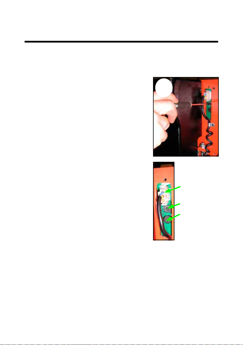
7.2 Adjusting the switch (ELFRRE/ELFSRRE)
The location of the reel carriage is decided by two inductive switches.
A) Inductive switch on thrust ring indicates when the
reel carriage is in position 0°.
A
When the reel carriage is in position 0°, the
inductive switch has to be placed right above the
indication pin on the thrust ring in a distance of
2-4 mm.
B) Inductive switch on the teeth of the little toothed
wheel. The number of the impulses indicates the
angle of the reel carriage.
The distance from the
inductive switch to the
tooth has to be 2-4 mm.
Inductive
switch
2-4 mm
B
7.3 Lubrication
Support bolts
To support the thrust ring, two support bolts are
placed behind the ring.
The bolts must only just touch the ring, and the
back of the ring has to be lubricated with grease,
so that the bolts slide smoothly.
Chains
The chains of the Reel Rotator have to be
lubricated at the yearly service check.
23

8.0 Fault location key
When the Reel Rotator is used every day, adjustments and the replacement of worn
parts might be necessary.
Adjustments and minor repair can easily be made on the spot. Major repairs should,
however, be carried through by the dealer who has a well-trained staff and the
necessary special tools.
Before asking the dealer for assistence...
...try the fault location key!
SYMPTOMS AND OBSERVATIONS
A Pump does not run when the UP button is pressed
B Truck does not lift when the UP button is pressed
C Truck does not lift to max. height
D The reel carriage lowers after being raised
E The reel carriage does not not lower when DOWN button is pressed
F The reel carriage cannot be lowered fully
G Truck is unable to lift the max. load
H Truck lifts slowly
I The reel carriage does not lift horizontally
J Steering wheel does not drive evenly

Cause Mending
A
B
C
D
E
Oil deficiency
Battery discharged
Fuse blown
10 Amp or 100 Amp
Cables defective
Max. load exceeded
Air in hydraulic system
Pressure relief valve
incorrectly adjusted
Leakage in hydraulic system
Visible oil leakage
Reel carriage needs
adjustment
Solenoid or check valve
defective
Defective valves
in pump
Steering wheel out
of adjustment
Defective
solenoid valve
See point 6.1/6.2
See separate
instruction
See point 5.1
See point 5.2
See point 4.1
See point 6.6
Contact
the dealer
Contact
the dealer
See point
6.3/6.4/6.8
Contact
the dealer
Contact
the dealer
See point 6.5
Contact
the dealer
F
G
H
I
J
If the problem cannot be
solved by using the fault
location key...
...please contact
your dealer!
25

9.0 Good service after purchase
9.1 Ordering spare parts
The correct spare parts are obtainable from your dealer.
When ordering, please state:
• Serial number of the product
• Type and width/length of the product
• Spare part no. Please nd spare part no. on www.logitrans.com
9.2 Warranty/Compensation
Spare parts delivered during the warranty period will be invoiced. A credit note will
be sent immediately after we have received and tested the defective parts and
found that the warranty conditions have been met.
9.3 Service and repair
You should be able to make adjustments and perform minor repairs on the spot.
However, major repairs should be left to the dealer who has well-trained personnel
and the necessary special tools.
9.4 Warranty
The warranty covers material and assembly defects which, subject to inspection by
us or our representative, are deemed to be faults or deciencies that prevent normal
use of the parts concerned. Such affected parts shall be sent to your Logitrans
dealer carriage paid within the warranty period in force at the time in question,
together with a copy of the documentation for the service performed
(B284 - see the back page). The warranty does not cover normal wear and
adjustments. The warranty period is based on singleshift working.
The warranty shall no longer apply if
• the product has been used incorrectly,
• the product is used in environments for which it was not designed,
• the product has been overloaded,
• replacements of parts have been made incorrectly or original parts have not been
used and consequential damages have arisen,
• if the product is changed or accessories, not being approved by Logitrans, are used.
• it can not be proved that a qualied technician has performed the service check
according to the requirements stated in the instruction manual (see the back page).
9.5 Liability exemption
The manufacturer accepts no responsibility for personal injury or material damage
arising from deciencies, defects or improper usage. The manufacturer accepts
no responsibility for lost earnings, operating losses, lost time, lost prots or similar
indirect losses incurred by the purchaser or a third party.
26

27

Periodic service and safety inspection
Service check is required once each year.
Safety inspection should be performed by the dealer or other qualied
persons at least once each year, unless local regulations state
otherwise.
The safety inspection to be performed on the basis of form no. B0342
and proved on form no. B284. Forms and instructions for the safety
inspection are available at your dealer.
S 995
ELRR-L-EN
16022016
28
 Loading...