

Logitek Standard Elec. Cable Manufacturing MON-10 User Manual
Logitek
M ON-10
Meter Monitor
& Switcher
Operation & Ser vice Manual

All information contained herein is con
fidential. No portions of this manual
maybe reproducedby anymeanswith
out written permission from Logitek
Electronic Systems, Inc.
COPYRIGHT 1990, LOGITEK
ELECTRONICSYSTEMS,INC.
-
-

MON-10
INSTRUCTION MANUAL
Table of Contents
SECTION 1 — GENERAL INFORMATION
1-1 General Description. . . . . . . . . . . . . . . . . . . . . . . . . . . . . . . . . . . . . . . . . . . . . . . . . . 2
1-2 Physical Description . . . . . . . . . . . . . . . . . . . . . . . . . . . . . . . . . . . . . . . . . . . . . . . . . 2
1-3 Electrical Specifications. . . . . . . . . . . . . . . . . . . . . . . . . . . . . . . . . . . . . . . . . . . . . . . 2
1-4 Instrument Identification . . . . . . . . . . . . . . . . . . . . . . . . . . . . . . . . . . . . . . . . . . . . . . 2
1-5 Where to find help . . . . . . . . . . . . . . . . . . . . . . . . . . . . . . . . . . . . . . . . . . . . . . . . . . . 2
SECTION 2 — PREPARATION FOR USE
2-1 Initial Inspection. . . . . . . . . . . . . . . . . . . . . . . . . . . . . . . . . . . . . . . . . . . . . . . . . . . . . 3
2-2 Claims . . . . . . . . . . . . . . . . . . . . . . . . . . . . . . . . . . . . . . . . . . . . . . . . . . . . . . . . . . . . . 3
2-3 Repacking for Shipment . . . . . . . . . . . . . . . . . . . . . . . . . . . . . . . . . . . . . . . . . . . . . . 3
2-4 Installation . . . . . . . . . . . . . . . . . . . . . . . . . . . . . . . . . . . . . . . . . . . . . . . . . . . . . . . . .3
2-5 Connecting Inputs and Outputs. . . . . . . . . . . . . . . . . . . . . . . . . . . . . . . . . . . . . . . . . 3
SECTION 3 — OPERATING INSTRUCTIONS
3-1 Input Selector Pushbuttons . . . . . . . . . . . . . . . . . . . . . . . . . . . . . . . . . . . . . . . . . . . . 4
3-2 SOURCE Switch . . . . . . . . . . . . . . . . . . . . . . . . . . . . . . . . . . . . . . . . . . . . . . . . . . . . 4
3-3 METER Switch . . . . . . . . . . . . . . . . . . . . . . . . . . . . . . . . . . . . . . . . . . . . . . . . . . . . . 4
3-4 VOLUME Control. . . . . . . . . . . . . . . . . . . . . . . . . . . . . . . . . . . . . . . . . . . . . . . . . . . . 4
SECTION 4 — PRINCIPLES OF OPERATION
4-1 General Information. . . . . . . . . . . . . . . . . . . . . . . . . . . . . . . . . . . . . . . . . . . . . . . . . . 5
4-2 Fuse. . . . . . . . . . . . . . . . . . . . . . . . . . . . . . . . . . . . . . . . . . . . . . . . . . . . . . . . . . . . . . 5
4-3 Power Supply . . . . . . . . . . . . . . . . . . . . . . . . . . . . . . . . . . . . . . . . . . . . . . . . . . . . . . 5
4-4 Switching and Amplification Circuitry. . . . . . . . . . . . . . . . . . . . . . . . . . . . . . . . . . . . . 5
SECTION 5 — REPLACEMENT PARTS LIST
5-1 MON-10. . . . . . . . . . . . . . . . . . . . . . . . . . . . . . . . . . . . . . . . . . . . . . . . . . . . . . . . . . . 6
SECTION 6 — MANUFACTURERS LIST
SECTION 7 — DIAGRAMS
Page i ** MON-10 Instruction Manual **

SECTION 1 — GENERAL INFORMATION
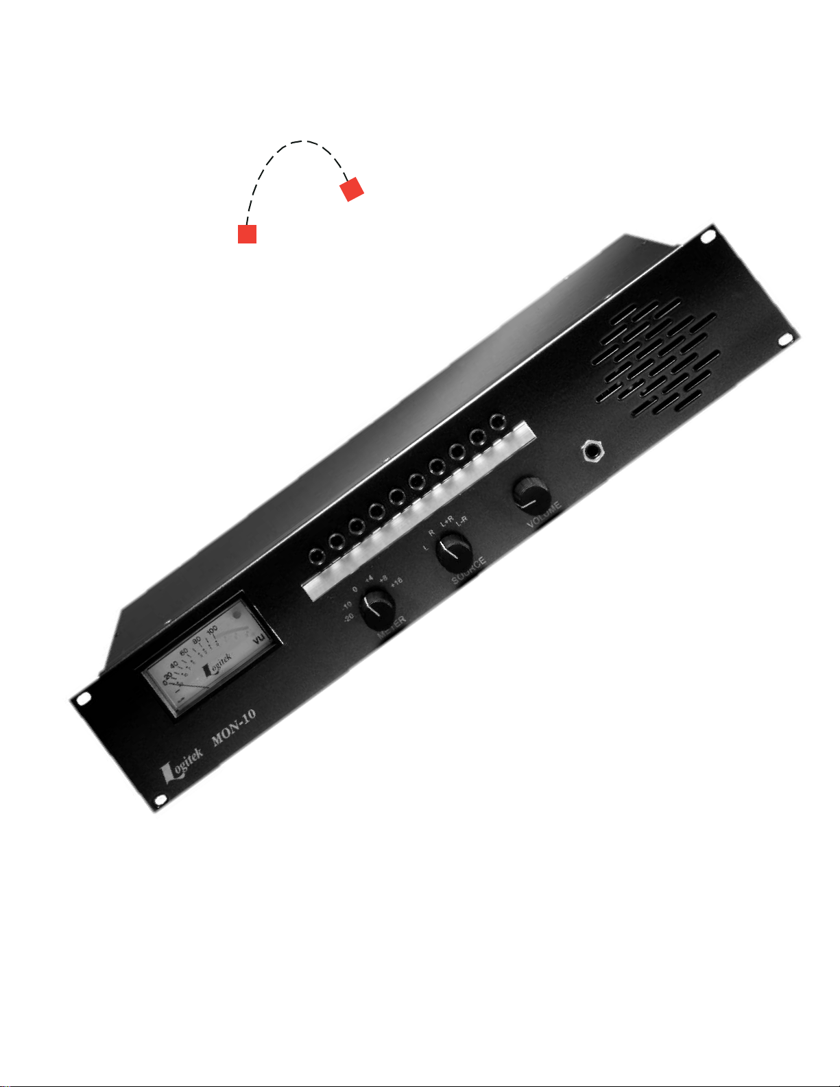
1-1 General Description
The Logitek MON-10 is a mechanical routing
switcher,asix-rangeVUmeter andasix-wattamplifier
all in one convenient rack-mounted unit.
The MON-10 features ten balanced stereo inputs,
any one of which can be selected using front-panel
pushbuttons. The selected input is passively fed to
balanced output ter minals on the rear panel.It is also
buffered and fed to a four-position source mode
switch. This switch selects whether the meter and
monitor will be fed the left channel, the right channel,
the mono sum (L+R) or the out-of-phase difference
(L-R).
Theoutput ofthe sourcemode switchfeedsameter
amp,which inturn feeds a built-in VU meter and peak
LED. The VU meter can be switched between any of
six ranges, as determined by the front panel meter
switch.The mode switchalsofeedsa six-watt monitor
amp, which in tur n feeds either a built-in speaker,
headphones, or an external speaker.
1-2
Physical Descr iption
The Logitek MON-10 is constr ucted within a 3 1/2"
Hx19"WX7"Dcabinet, which is designed to take up
two rack spaces in a standard 19" equipment rack.
The power cord, fuse and all connections except the
headphone jack are located on the rear panel. The
headphone jack, meter, speaker and all controls are
located on the unit’s front panel.
andser ial numberappearon a labelon the backof the
unit near the power cord.All correspondence to your
Logitek dealer or to the Logitek factory shouldrefer to
the model number and serial number.
1-5
Where to find help
Logitek customer service personnel are available
tohelp withanyquestions,commentsor problemsyou
mighthavewith theMON-10,both duringandafter the
warranty period. Our hours of operation are 8AM to
5PM central time.We may be contacted in one of the
following ways:
By Phone: 877-231-5870 (U.S.A. & Canada)
or 713-664-4470
By Fax: 713-664-4479
By Email: help@logitekaudio.com
By Mail: Logitek Electronic Systems, Inc.
5622 Edgemoor Drive
Houston, TX 77081
USA
1-3
Electrical Specifications
Number of Inputs:
10 stereo
Input Level:
normal 0 dBu
maximum +23 dBu
Input Impedance:
140kohms
Line Output Level:
Line output switching is passive so the output
level, impedance and balancing is the same as
that of the selected input.
Speaker Output Level:
maximum 6 watts
Speaker Output Noise:
ref. 0 dBu input 60 dBu
AC Line Input Voltage:
50-60 hz 105-129 V
(optional factory modification for 220-240 VAC)
1-4
Instrument Identification
The MON-10 is identified by a model number and a
three or four digit serial number. The model number
** MON-10 Instruction Manual ** Page 2
 Loading...