

Page 1
Logitek
Looggiitteekk
L
ElleeccttrroonniiccSSyyssttee
E
Mosaic Reference Manual
mss
m
Revision 1.12
Jan 2006
Page 2

Logitek Electronic Systems, Inc.
5622 Edgemoor Drive
Houston, Texas 77081
Tel 713-664-4470
Fax 713-664-4479
Email [email protected]
Web www.logitekaudio.com
Contents © 2005 Logitek Electronic Systems, Inc
Notice
Every effort has been made to supply complete and accurate information. However, Logitek Electronic Systems, Inc. assumes no
responsibility for its use, nor any infringement of patents or other rights of third parties, which would result.
Worldwide rights reserved. Except for your own personal use, no part of this publication may be stored in a retrieval system,
transmitted or reproduced in any way, including but not limited to photocopy, photograph, magnetic or other record, without the
prior agreement and written permission of Logitek Electronic Systems, Inc.
Logitek is a trademark of Logitek Electronic Systems, Inc.
All other trademarks acknowledged.
All specifications are subject to change without notice.
Page 3
1
Introduction
Logitek
Document Revisions
Date Revision Author Notes
May 2005 1.0 Paul Dengate First release of Mosaic manual
November 2005 1.1 Paul Dengate Renamed to Mosaic Reference Manual
User Operations content now duplicated in Mosaic Operator’s Manual
Updated Release Notes (Appendix A) for Mosaic v2.x software
Added details of new Mosaic commands (Appendix E)
December 2005 1.11 Paul Dengate Final Release of Mosaic v2.1 updates & additions
Updated Device Number details in Chapter 4
Corrections to Mosaic commands (Appendix E)
January 2006 1.12 Paul Dengate Updated Power Supply details with respect to studio noise suitability (Chapter 3)
Updated mounting details for new Meter Bridge mounts (Chapter 3)
Updated Default Device Numbers for Mosaic v2.11 PSU firmware (Chapter 4)
Removed MLX-EQ module pending re-design (Chapter 5)
Updates for Mosaic v2.11 firmware notes (Appendix A)
Corrections to Mosaic commands (Appendix E)
Typo corrections
Logitek Mosaic Reference Manual
1
Page 4

1
Introduction
Logitek
Contents
1 Introduction ........................................................................................................................... 4
About this Manual............................................................................................................... 4
About Mosaic...................................................................................................................... 5
System Requirements..........................................................................................................6
2 Unpacking ..............................................................................................................................8
Parts List .............................................................................................................................8
Unpacking .......................................................................................................................... 8
3 Physical Installation ............................................................................................................... 9
Power Supply Unit..............................................................................................................9
Mosaic Frames .................................................................................................................... 9
Mosaic Cutouts ................................................................................................................. 10
Meter Bridges ................................................................................................................... 12
Connections...................................................................................................................... 13
4 Configuration........................................................................................................................ 16
COM Port Configuration ................................................................................................... 16
Audio Engine Configuration............................................................................................... 16
CommandBuilder Triggers................................................................................................. 16
Device & Bus Addressing .................................................................................................. 17
5 Operation ............................................................................................................................. 20
Mosaic Fader Modules ...................................................................................................... 21
Mosaic Control Modules ................................................................................................... 25
6 Maintenance.........................................................................................................................30
Warranty .......................................................................................................................... 30
Firmware Updates............................................................................................................. 30
Component Replacement .................................................................................................32
Appendix A Release Notes.......................................................................................................34
What’s New...................................................................................................................... 34
Upgrade Strategies ............................................................................................................ 35
Current Versions ............................................................................................................... 35
Version History .................................................................................................................36
Known Issues .................................................................................................................... 38
Appendix B Specifications ....................................................................................................... 39
Mosaic Frames .................................................................................................................. 39
Mosaic Modules................................................................................................................ 39
Meter Bridges ................................................................................................................... 40
Mosaic Power Supply........................................................................................................ 40
Appendix C Pinouts ................................................................................................................. 41
To Audio Engine ...............................................................................................................41
GPIs..................................................................................................................................41
To Surface ........................................................................................................................42
Appendix D Spares Kit ............................................................................................................. 43
2
Logitek Mosaic Reference Manual
Page 5

1
Introduction
Contents ........................................................................................................................... 43
Appendix E Additional Protocol Commands ..........................................................................44
Mosaic Busses ................................................................................................................... 44
Mosaic Feature Commands ...............................................................................................46
Logitek
Logitek Mosaic Reference Manual
3
Page 6
1
Introduction
Logitek
1 Introduction
About this Manual
This manual describes the installation and operation of the Logitek Mosaic control surface.
Intended Audience
This manual is aimed at Engineers responsible for installing, configuring and supporting a Logitek
Console Router System
In the context of a system installation, or to become familiar with the entire
System, the reader should also reference:
¾ Audio Engine Installation & Operation Manual
¾ AEConfig User’s Manual
¾ Supervisor User’s Manual
¾ CommandBuilder User’s Manual
The content of this manual relevant to console operators (Chapter 5) is also duplicated in the
separate
of using the surface in a broadcast environment.
Mosaic Operator’s Manual. This provides announcers and operators with a brief overview
with the Mosaic surface.
Logitek Console Router
Manual Conventions
The following conventions are used in this manual:
This text indicates a menu choice to be made, with an arrow separating a multi-level selection,
eg Control Panel
within Windows.
¾
Users & Passwords. This can be a menu choice in a Logitek application, or
¬ Indicates a “see-also” section in this manual, or another Logitek manual.
The exclamation symbol signifies an important note or critical information.
This text represents a command, script block example, instruction to
be typed, or directory path.
TIP: A useful tip from our knowledge base!
4
Logitek Mosaic Reference Manual
Page 7
1
Introduction
Logitek
About Mosaic
Art meets technology in the Mosaic digital console, the latest in control surface designs from Logitek
Electronic Systems. As with its namesake, the Mosaic is composed of a series of pieces (modules) to
provide the highest possible flexibility in design and operation while bringing you an attractive visual
centerpiece for your broadcast installations.
First released in 2005,
many new features, including multi-color on/off lamps, variable intensity softkey buttons, and singlebutton access to more functions. The
configured to suit the user’s requirements. These modules include:
¾ MLX-FADER Fader Module (double width)
MLX-MON Monitor Module (double width)
¾
MLX-NSOFT Narrow Softkey Module (single width)
¾
¾ MLX-WSOFT Wide Softkey Module (double width)
MLX-EQ Audio Processing Module (double width)
¾
¾ MLX-BLANK Blank Module (single width)
In addition, the
The main frame is available in a number of different sizes to accommodate a variety of console sizes
and fader numbers. The frame is designed to be sunken into a desk for permanent installation.
Monitor Bridge is available in both wide and narrow form factor.
Mosaic was designed to replace the Numix series of consoles, and adds
Mosaic surface is based on a series of modules that can be
Logitek Mosaic Reference Manual
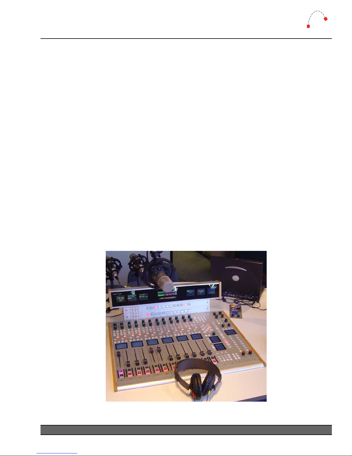
Figure 1 – Mosaic 12 Fader Console
5
Page 8
1
Introduction
Logitek
System Requirements
Mosaic is designed to connect to a Logitek Audio Engine running DSP version 3.x or later. Certain
Mosaic functions may require a specific type or release of DSP card. Contact Logitek Electronic
Systems
facility.
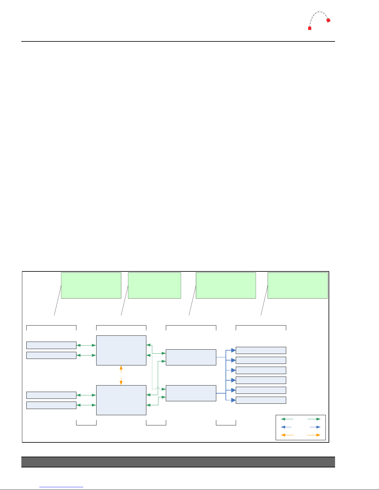
System Architecture
Put simply, the Mosaic surface is just a remote control panel for the Audio Engine. Unlike
traditional analog consoles, no audio passes through the
the cue speaker audio). The
Protocol, with all audio processing occurring inside the Audio Engine.
The mixing, routing and processing of audio is not dependant upon PCs. However, additional
functionality, such as macro buttons, scene snapshots, intercoms, delay control and software tools
interface to the system using the
Whilst
now sold with this PC suite, as it unlocks the true power of the
contains many programmable buttons, which require scripting using
functionality for these buttons is then executed by
critical functions, such as delay control or studio switching, running a
is highly recommended.
or your reseller if you are unsure, or are adding a Mosaic surface to a pre-existing Logitek
Mosaic or its faders (with the exception of
Mosaic talks to the Audio Engine using the Logitek Command
Supervisor PC application.
Supervisor is not a requirement to run a Logitek Console Router System, most systems are
Logitek system. The Mosaic surface
CommandBuilder. The
Supervisor. If these buttons are performing on-air
Dual Supervisor configuration
Surfaces are remote
control panels for
Audio Engine
Audio Engines
process Audio and
GPI control events
Supervisor executes
scripts and provides
gateway to IP world
Client PCs interact
with Audio Engines
via Supervisor
Surfaces Audio Engines Supervisor PCs
Console Surfaces
Control Panels
Console Surfaces
Control Panels
Serial Comms Serial Comms TCP/IP
6
Logitek Mosaic Reference Manual
AE1
Fibre Audio Network
AE2
Figure 2 - Logitek System Architecture
Supervisor PC
Main
Supervisor PC
Backup (optional)
Client PCs
Software vTools
Software vTools
Software vTools
Software vTools
Software vTools
Software vTools
Serial
TCP/IP
Fibre
Page 9
1
Introduction
Logitek
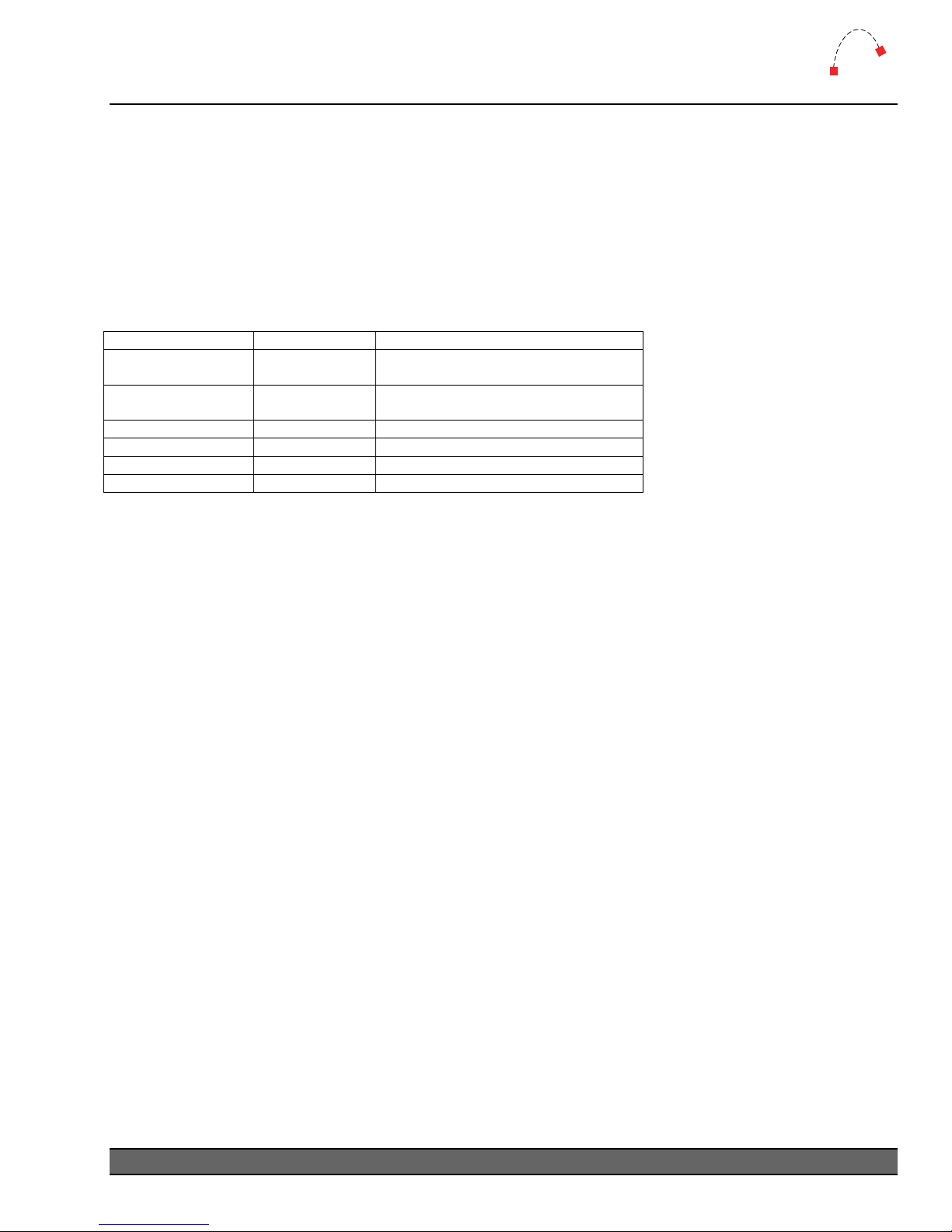
Compatibility Matrix
Mosaic is designed for use with Logitek Audio Engine 3.x or later. The Mosaic retains compatibility
with other surfaces for the majority of its features.
Support for
of the system.
Mosaic specific additional features has been progressively added to other components
Mosaic v2.x firmware was released in November 2005.
Following is the minimum software release version/date that is required for
Mosaic support.
Component General Support Additional Features
AE-C2 Controller Card
AE-C6 Controller Card
SharcAttack DSP v3.x v3.60 Jun 2005 or later
LoneSharc DSP v3.x Contact Logitek or your reseller
Supervisor 2002 / v3 v3.0 November 2005
CommandBuilder 2002 v3.0 November 2005
AEConfig 2002 v3.0 for 16 character
v3.x
v3.x
v3.25 Nov 2005 for extra cue/aux meters
v3.63 Nov 2005 for extra cue/aux meters
v3.63 Nov 2005 for extra cue/aux meters
¬ See Appendix A for Mosaic related release notes and version information.
Logitek Mosaic Reference Manual
7
Page 10

2
Unpacking
Logitek
2 Unpacking
This section details what you should do when unpacking your newly arrived Mosaic surface.
Parts List
The exact list of parts received will vary depending on your order, but should generally include:
¾ 1 x
¾ 1 x fully assembled
¾ 1 x wide or narrow meter bridge assembly
¾ 2 x mounting brackets for meter bridge, or optional bridge frame for additional 2 x MLX42
¾ 1 or 2 x “Telco” cables to link console to PSU (number depends on console size)
¾ 1 x RJ45-RJ45 patch cable to link PSU and Audio Engine (if in close proximity)
¾ 1 x Hex tool to allow removal of modules and faders
You will receive a parts list with the system that is specific to the modules on your order.
Mosaic Power Supply fitted with one PSU module, or two PSU modules (option)
Mosaic frame, containing modules as ordered
Unpacking
Carefully unpack the cartons whilst looking for any signs of shipping damage. You may wish to save
the shipping cartons until the operation of the system is verified.
Report any damage to the shipping carrier immediately. Verify that the contents of each box match
the packing list and report any discrepancies immediately to
Contacting Logitek
In the event of a shipping problem, you can contact Logitek Electronic Systems in several ways:
U.S. Mail Logitek Electronic Systems, Inc.
522 Edgemoor Drive
Houston, Texas 77081
Telephone 877-231-5870
713-664-4470 (outside U.S. and Canada)
Logitek in writing.
8
Logitek Mosaic Reference Manual
Page 11

3
Physical Installation
Logitek
3 Physical Installation
The Mosaic surface is designed to be mounted in a desk cutout in a permanent studio installation.
Meter Bridge can be screwed to the desk and mounted using the supplied mounting brackets.
The
Power Supply Unit
The Power Supply Unit is a 2-RU sized rack mount box, designed for mounting in an under-desk
studio rack. If the supplied cables are not long enough to allow for convenient mounting, custom
length cables are readily available.
Power Supply is suitable for mounting in a studio environment and has been designed to be
The
silent. The modules are a low-noise type and all electronics is solid-state (no mechanical relays).
Power Supply contains one or two switch-mode supply modules, with a power indicator for
The
each module on the front panel.
Power inlet is via a single IEC connector on the rear of the
supplied only for US installations. International customers may contact their reseller for the supply
of power cables if required.
As the power supplies are of switch-mode type, there is no voltage selection required.
Power Supply Unit. A power cable is
Mosaic Frames
A number of Mosaic frame sizes are available, depending on the total number of faders and control
modules. Each module takes up either one or two “slots” in the frame. The Fader, Monitor,
Processing and Wide Softkey modules take two slots. The Narrow Softkey and Blank Panel take
up one slot.
The frame will be shipped with the modules connected and fitted as ordered. These modules can
be moved if desired. If moving modules, please retain the same internal COM port connections as
the surface shipped with. If the COM port connections are changed, the device addressing for those
modules will change.
Logitek Mosaic Reference Manual
9
Page 12
3
Physical Installation
Logitek
Mosaic Cutouts
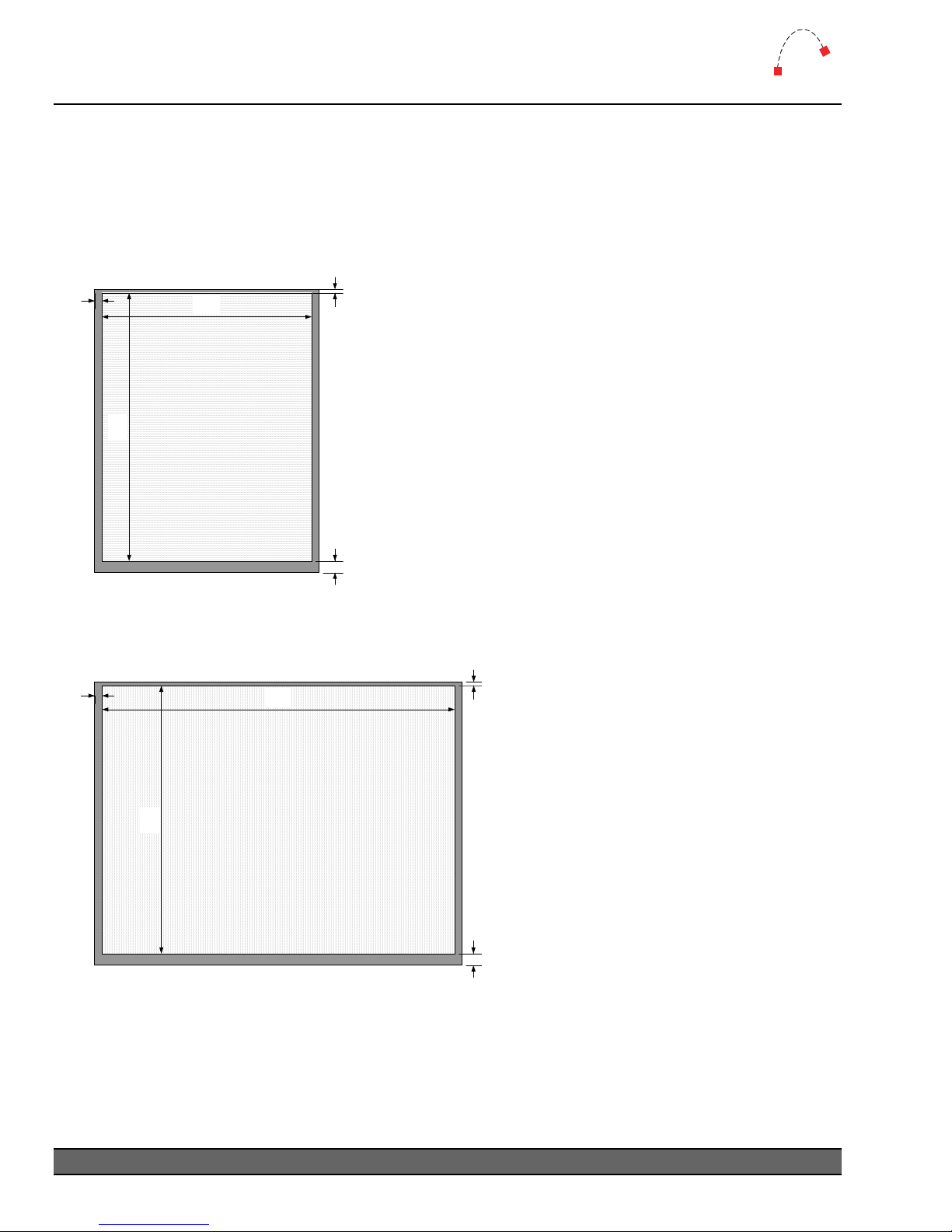
The Mosaic frame should be fitted into a desk, using the cutout sizes below. The height of the
cutout remains the same for each frame size – only the width varies.
MLX-F10
0.50in
13mm
18.40in
467mm
14.40in
365mm
MLX-F10
Cutout
The MLX-F10 frame has capacity for 10 units. Suggested
configurations include:
0.25in
6.4mm
¾ 6 faders / Wide Softkey / Monitor
¾ 4 faders / Wide Softkey / EQ / Monitor
¾ 4 faders / Wide Softkey / Narrow Softkey / Blank /
Monitor
The required desk cutout for the MLX-F10 is 14.4 x 18.4in /
365 x 467mm.
0.80in
(20mm)
Figure 3 - MLX-F10 Cutout
MLX-F17
0.50in
13mm
24.20in
616mm
MLX-F17
18.40in
467mm
Figure 4 - MLX-F17 Cutout
Cutout
The MLX-F17 has capacity for 17 units.
0.25in
6.4mm
Suggested configurations include:
¾ 12 faders / Wide Softkey / Narrow
Softkey / Monitor
¾ 10 faders / Wide Softkey / Narrow
Softkey / EQ / Monitor
The required desk cutout for the MLX-F17
is 24.2 x 18.4in / 616 x 467mm.
0.80in
(20mm)
10
Logitek Mosaic Reference Manual
Page 13
3
Physical Installation
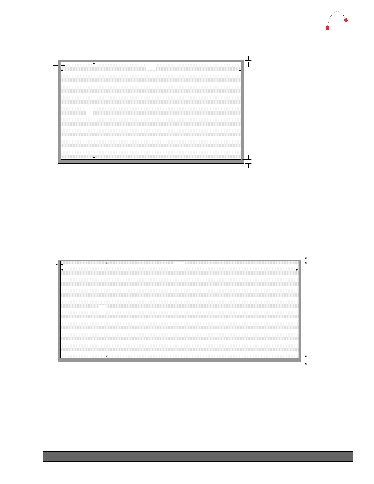
MLX-F24
0.50in
13mm
34.00in
864mm
0.25in
6.4mm
MLX-F24
18.40in
467mm
Cutout
0.80in
(20mm)
Figure 5 - MLX-F24 Cutout
The MLX-F24 has capacity for 24 units. Suggested configurations include:
¾ 18 faders / Wide Softkey / EQ / Monitor
¾ 18 faders / Wide Softkey / Narrow Softkey / Blank / Monitor
The required desk cutout for the MLX-F24 is 34.0 x 18.4in / 864 x 467mm.
MLX-F32
0.50in
13mm
45.20in
1148mm
Logitek
0.25in
6.4mm
MLX-F32
18.40in
467mm
Figure 6 - MLX-F32 Cutout
Cutout
The MLX-F32 has capacity for 32 units. Suggested configurations include:
¾ 24 faders / Wide Softkey / 2 x Narrow Softkey / Processing / Monitor
The required desk cutout for the MLX-F32 is 45.2.0 x 18.4in / 1148 x 467mm.
Logitek Mosaic Reference Manual
0.80in
(20mm)
11
Page 14
3
Physical Installation
Logitek
Meter Bridges
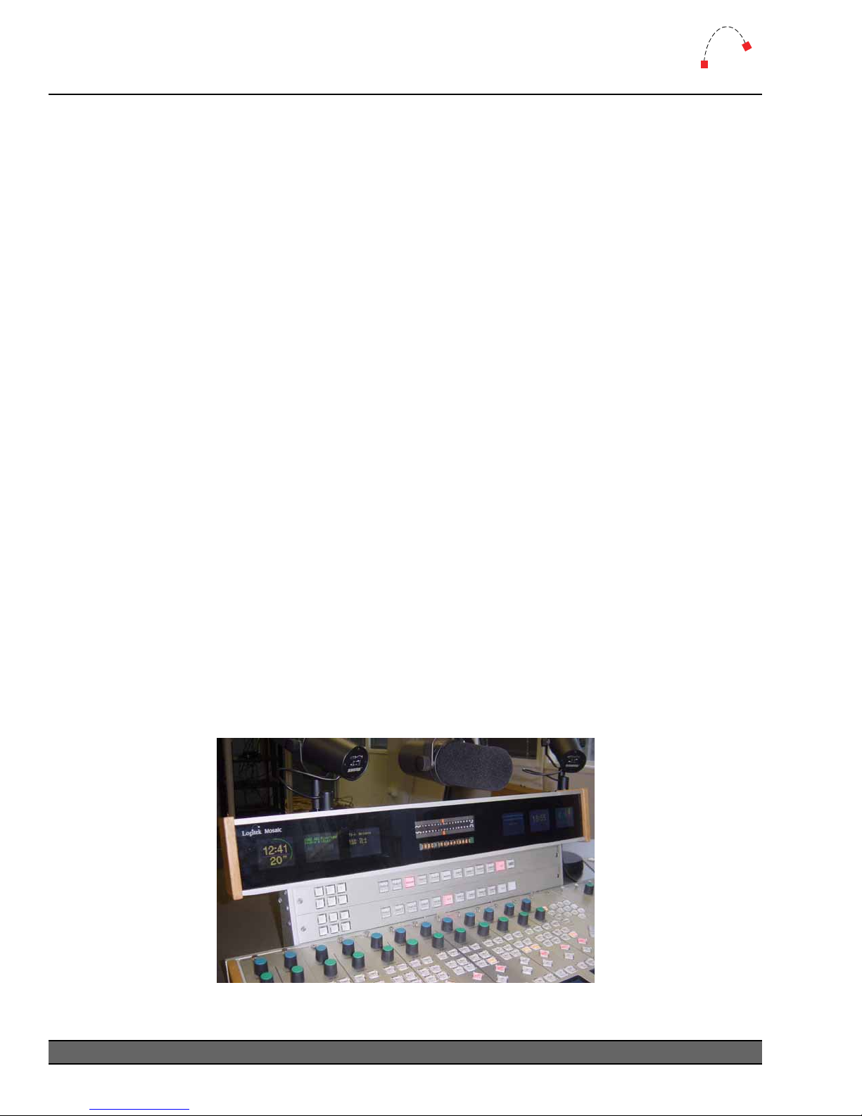
Two sizes of Meter Bridge are available. The Wide Bridge includes one high-resolution program
meter, and 6 color LCD screens for text, clocks and other meters. The Narrow Bridge also includes
the high-resolution meter, with two color LCD screens.
In addition, a special version of the Wide Bridge is available with space for two horizontal Narrow
Softkey modules, providing additional programmable softkey buttons.
Mounting
¾ Narrow & Wide Bridges supplied in 2005 have a flange at the bottom of each foot to allow
the assembly to be screwed into the furniture.
¾ Systems supplied in 2006 and beyond will have mounting brackets that bolt directly to the
rear of the console frame, removing the need for separate mounting holes in the furniture.
¾ The Wide Bridge with Button Riser still requires mounting to the studio furniture.
Narrow Bridge
¾ 13” W x 3.8” H x 2.6” D (330 mm x 97 mm x 66 mm)
¾ The standard mounting adds 2.4” (61 mm) to the height
Wide Bridge
¾ 23.6” W x 3.8” H x 2.6” D (599 mm x 97 mm x 66 mm)
¾ The standard mounting adds 2.4” (61 mm) to the height
Wide Bridge with Button Riser
¾ 23.6” W x 3.8” H x 2.6” D (599 mm x 97 mm x 66 mm)
¾ The 2 module slot riser adds 4.8” (122 mm) to the height
Figure 7 - Mosaic Wide Bridge with button riser
12
Logitek Mosaic Reference Manual
Page 15
3
Physical Installation
Logitek
Connections
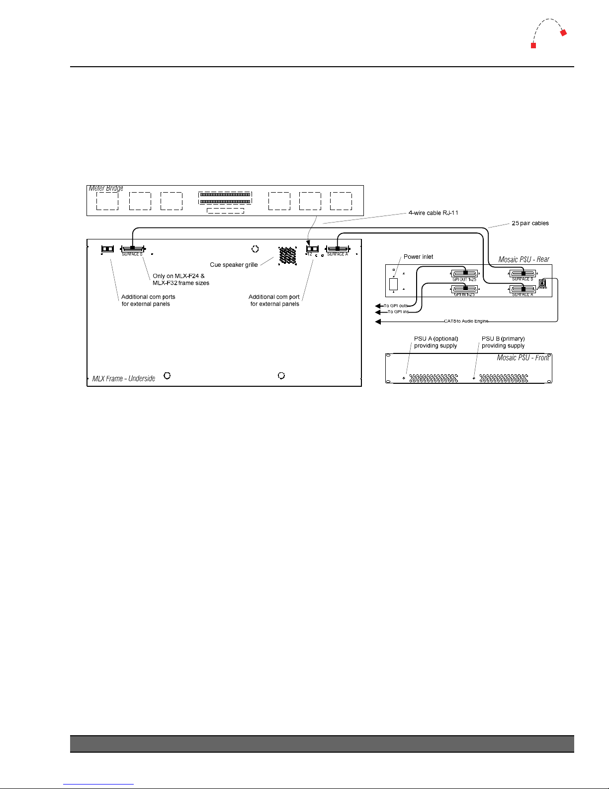
The Mosaic Power Supply Unit contains the control and GPI circuitry for the console. It connects to
the Logitek Audio Engine via a serial link. The Power Supply Unit connects to the Surface using
one or two 25-pair “Telco” cables. These cables carry the communication between each module
and the Power Supply Unit.
Figure 8 - Mosaic Connection Diagram
Surface to PSU
For the MLX-F10 and MLX-F17 frames, a single 25-pair Telco cable connects Power Supply Unit to
the Surface. For the MLX-F24 and MLX-F32 frames, two of these cables are used.
The required cables will be supplied with your
(3m).
If the supplied cables are not long enough, you can order Telco style cables from Logitek Electronic
Systems or a local supplier. The connectors are standard Telco style 50-pin Centronics Male plugs,
wired straight through (all pairs connected).
Alternative wiring schemes may reverse or drop pairs, so please ensure you specify straight through
wiring if purchasing custom-made cables.
Mosaic. The length of these Standard cables is 10’
¬ See Appendix B for connector pinouts.
Logitek Mosaic Reference Manual
13
Page 16

3
Physical Installation
Logitek
Surface to Meter Bridge
The Meter Bridge has a short 4-wire cable with an RJ-11 connector on the end. This is plugged into
the port labeled COM12. The cable length is suitable to mount the meter bridge behind the
frame. If alternative wiring is required, this can be replaced with a custom made cable using flat
telephone cable and RJ11 connectors.
Mosaic
Internal Module Connections
Inside the frame, the one or two 25-pair connectors (depending on frame size) are broken out to
individual port connections. There is generally no requirement to replace these cables, as the
lengths are made to suit the position of each module.
PSU to Audio Engine
The Mosaic Power Supply Unit connects to the Logitek Audio Engine using a balanced serial link.
Standard CAT5 or better cabling is recommended. The cable required will depend on the type of
controller card and connectors in the Audio Engine.
New systems are supplied with the AE-C6 controller card, which connects using an RJ45 at the
Audio Engine and
a DB9 connection at the Audio Engine.
Mosaic is supplied with a CAT5 patch lead, to connect the AE-C6 to the Mosaic Power Supply
The
Unit. This lead is sufficient for testing purposes; however, the Audio Engine will normally be located
away from on-air studios.
You can use a dedicated CAT5 cable or existing structured cabling. If using structured cabling
systems, care should be exercised to ensure the Audio Engine connections are not confused with
other network outlets and that the link is not unintentionally “un-patched”.
Mosaic. Older Engines running the AE-C2 card (supplied in 2004 or earlier) have
¬ See Appendix B for connector pinouts.
14
Logitek Mosaic Reference Manual
Page 17

3
Physical Installation
Logitek
GPIs
The Mosaic Surface has 25 GPI inputs and outputs for control of local studio devices.
GPI outputs are driven by optically-isolated, non-polarized, solid state switches, rated at 500ma at
50V AC/DC, with surge to 2A. These solid state devices do not conduct at low voltage, so cannot
switch an audio input. However, they are suitable for most control signals, and avoid problems with
relay contacts being damaged by surges. Caution should be exercised to avoid overloading the
switches. If driving a high current device, we recommend driving an external relay or switch.
The GPI inputs are a current source to +5VDC that is pulled to ground to activate. This makes it
suitable for control by push-button, relay or open collector. A diode protects against static and over
voltage. See the wiring diagram for polarity information if using non-standard activation methods.
GPI connectors are on Telco style 50-pin Centronics. As wiring schemes vary from station to station,
these cables are not supplied with the surface, but are available from Logitek Electronic Systems.
They can also be purchased from local suppliers in the required form.
Wiring is straight-through style, with Pair 1 corresponding to GPI #1 and so on. A male AMP style
50-pin connector is required to connect to the
single-ended cable with tails for punch-down to Krone style block or similar. There is one connector
for GPI inputs and another for GPI outputs.
Mosaic Power Supply Unit. We suggest ordering a
¬ See Appendix B for connector pinouts.
Logitek Mosaic Reference Manual
15
Page 18

4
Configuration
Logitek
4 Configuration
This chapter covers basic configuration information, relating specifically to the Mosaic surface.
Audio Engine setup and configuration is covered in detail in the following manuals:
Logitek Audio Engine User’s Manual
¾
¾ Logitek AEConfig User’s Manual
COM Port Configuration
The Mosaic contains 12 COM ports per 25-pair connector from the Power Supply Unit. These ports
are internally mounted to connect to each module, with one external COM port to connect to the
Meter Bridge.
By default, the Device Address to Com Port map is set inside the Mosaic Power Supply Unit
firmware, and will suit most installations. The defaults are shown on the following page. Mosaic v2
adds the ability to change the Com Port mapping, using hex commands sent from Supervisor.
These are stored in the power supply’s non-volatile RAM, so don’t need to be sent each power up.
¬ See Appendix E for Mosaic configuration commands.
Audio Engine Configuration
Configuration of the Audio Engine is done in AEConfig. Currently, there are no specific features that
are set by AEConfig – configuration is as per other Logitek Surfaces.
Currently, AEConfig does not include specific DSP table entries for the Mosaic. You should use a
Numix surface of the next nearest size when configuring a Mosaic. In the future, specific Mosaic
support will be added to AEConfig, however, the two consoles are compatible in DSP allocations.
¬ See the AEConfig User’s Manual for information on configuring Audio Engines.
CommandBuilder Triggers
The Mosaic surface contains many programmable buttons and features. These features are scripted
in “triggers” in CommandBuilder, and executed by Supervisor.
¬ See the CommandBuilder User’s Manual for information on writing Triggers.
The CommandBuilder manual includes details and examples of Mosaic specific features, such as
Monitor Hotkeys, Colored On/Off Lamps, Multi-brightness lamps and more. The programming of
these features does require a certain level of familiarity with the system. If you need assistance,
please contact Logitek Electronic Systems or your reseller.
16
Logitek Mosaic Reference Manual
Page 19

4
Configuration
Logitek
Device & Bus Addressing
Each device (such as a fader input or button panel) requires its own Device Number. Within that
device, each button, lamp and feature has a Bus Number. Together, the Device and Bus Numbers
allow the Audio Engine and Surface to communicate.
When configuring the Mosaic’s programmable buttons in CommandBuilder, you will require the
Device Number and Bus Number for each button or lamp. The information below will help you
determine the addressing scheme in use on your Mosaic. As the layout of the Mosaic is extremely
flexible, the addressing will vary and is usually unique to your station.
Please note that addressing is configurable, and any defaults listed may have been overridden.
Modules
Module How Addressing is determined Max Modules Supported
MLX-MON Uses the standard Monitor, Headphones, Guest/Studio, Cue Gain, External Cue
Gain & TB Return addressing
MLX-WSOFT Uses chan29 (lamps) and chan30 (switches) 2 *
MLX-NSOFT Device Pair determined by COM port allocation (configurable)
Low device = lamps, High device = switches
MLX-FADER Device Pair determined by COM port allocation (configurable)
Low device = left fader, High device = right fader
MLX-WBRIDGE
MLX-NBRIDGE
Uses chan33 for Left LCD screens and chan34 for Right LCD screens
Should be connected to Port 12 on underside of Mosaic, or Port 17 for 2
nd
bridge
* Support for replication between dual Monitor, Wide Softkey or Bridge modules is scheduled for
addition to Mosaic v2.2 software in 2006.
2 *
Limited by available ports
12 modules (24 faders)
subject to available ports
2 *
Device Numbers
In Mosaic v1.x the Device Number of a module is determined by its firmware and position. In
some cases, non-default port mapping was hard-coded into the ROM to suit user requirements.
In Mosaic v2.0 and above (from November 2005), the Device Number allocated to COM ports is
user configurable. An international set of default mappings is installed in the ROM, but this map is
adjustable using
When using Device addressing, we recommend you use the SURF# CHAN# notation in
CommandBuilder. This provides more flexibility for future changes, and allows you to relocate the
surface or re-use the code on another port by finding and replacing the
below is the hex equivalent of the channels of a Surface connected to Audio Engine Port 1.
Logitek Mosaic Reference Manual
ASM commands in your Init Trigger.
SURF# instances. Shown
17
Page 20

4
Configuration
Logitek
Default Device Numbers
Following is the default Device COM Port map that ships with Mosaic v2.x.
These defaults are designed to suit most standard consoles, up to 24 faders. In some cases it may be
necessary to override the default mapping to support non-standard requirements.
Port Connector Standard Module Alternative Channel (dec) Port 1 Device (hex)
1 A 1 Fader 1/2 1 & 2 OB & OC
2 A 2 Fader 3/4 3 & 4 OD & OE
3 A 3 Fader 5/6 5 & 6 OF & 10
4 A 4 Fader 7/8 7 & 8 11 & 12
5 A 5 Fader 9/10 9 & 10 13 & 14
6 A 6 Fader 11/12 11 & 12 15 & 16
7 A 7 Wide Softkey A 29 & 30 27 & 28
8 A 8 Fader 13/14 Narrow Softkey 1 13 & 14 17 & 18
9 A 9 Monitor Module A 25;26;27;31;32 23;24;25;29;2A
10 A 10 Fader 15/16 Narrow Softkey 2 15 & 16 19 & 1A
11 A 11 (under) External Softkey Narrow Softkey 3 17 & 18 1B & 1C
12 A 12 (under) Meter Bridge A 33 – 40 2B – 32
13 B 1 Fader 17/18 Narrow Softkey 4 17 & 18 1B & 1C
14 B 2 Fader 19/20 Narrow Softkey 5 19 & 20 1D & 1E
15 B 3 Fader 21/22 Narrow Softkey 6 21 & 22 1F & 20
16 B 4 Fader 23/24 Narrow Softkey 7 23 & 24 21 & 22
17 B 5 Spare No default set No default set
18 B 6 Spare No default set No default set
19 B 7 Wide Softkey B 29 & 30 27 & 28
20 B 8 Spare No default set No default set
21 B 9 Monitor Module B 25;26;27;31;32 23;24;25;29;2A
22 B 10 Spare No default set No default set
23 B 11 (under) Meter Bridge B 33 – 40 2B – 32
Dual Controls / Split Consoles
The default Device Number map above has been designed to support split consoles operating in a
“Dual Control” mode. However, as of Mosaic v2.1, replication of commands between modules is
not current supported. This feature is planned for future implementation.
In a Dual Control environment, the Mosaic PSU would connect to the two surface frames via the
“Surface A” and “Surface B” connectors. Up to 16 faders could be supported on each surface, with
mirrored Monitor Module, Wide Softkey and Meter Bridges in each.
18
Logitek Mosaic Reference Manual
Page 21
4
Configuration
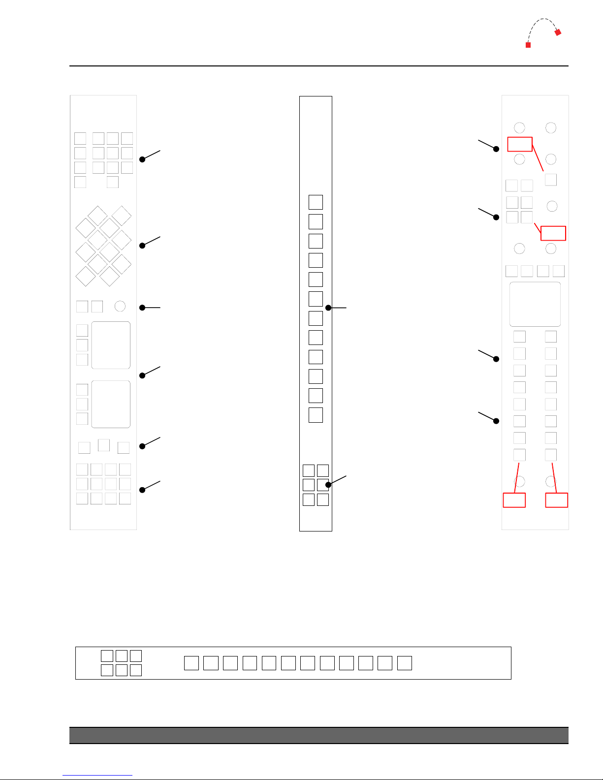
Bus Numbers
Logitek
32 33
34 35
36 37
38 39
40 41
42 43
30 29
31
79
80
81
82
83
84
86
85
87
88 89 90 91
92 93 94 95
96 97 98 99
Timer Buttons
Use AE effect
command to control
Scene Buttons
BUS32 to 43
TAKE (BUS29)
CANCEL (BUS30)
SELECT (BUS31)
Screen Text Buttons
BUS79 to 84
Misc Buttons
BUS85 to 87
Softkey Buttons
BUS88 to 99
ML
NSOX-FT
32
33
34
35
36
37
38
39
40
41
42
43
44 45
46 47
48 49
TB In Mute
BUS3
Guest TB/Follow Mon
BUS2 & 15
Guest Hotkeys
BUS16 & 17
Buttons
BUS32 to 43
H/P & Mon Features
See Right
H/P & Mon Hotkeys
BUS16 to 17
Softkey Buttons
BUS44 to 49
MLX-MONMLX-WSOFT
ch32
3
152
16 17
ch25
21
15
16
17
18
19
20
9
16
17
18
19
20
ch26ch27
The MLX-NSOFT module can also be mounted horizontally in the Wide Meter Bridge Button
Riser. In this case the bus addresses do not change, but if the small Softkeys are on the left, the bus
numbers run from right to left. There is nothing to stop the user from mounting the MLX-NSOFT
module the other way, with the small softkey panel on the right hand side.
MLX-
48
49
46
47
44
45
NSOFT
323334353637383940414243
Logitek Mosaic Reference Manual
19
Page 22
5
Operation
Logitek
5 Operation
At first glance, your Logitek Mosaic may appear a little daunting. But if you’ve had experience with
broadcast consoles before, you’ll soon be at home, finding your way around quite easily.
Logitek Electronic Systems has been manufacturing broadcast consoles for decades, so we
understand how to make control surfaces that are both powerful and straightforward. During the
design of the Mosaic, customers and operators provided feedback that helped shape the final
product. So we’re confident you’ll find the Mosaic a joy to use on-air.
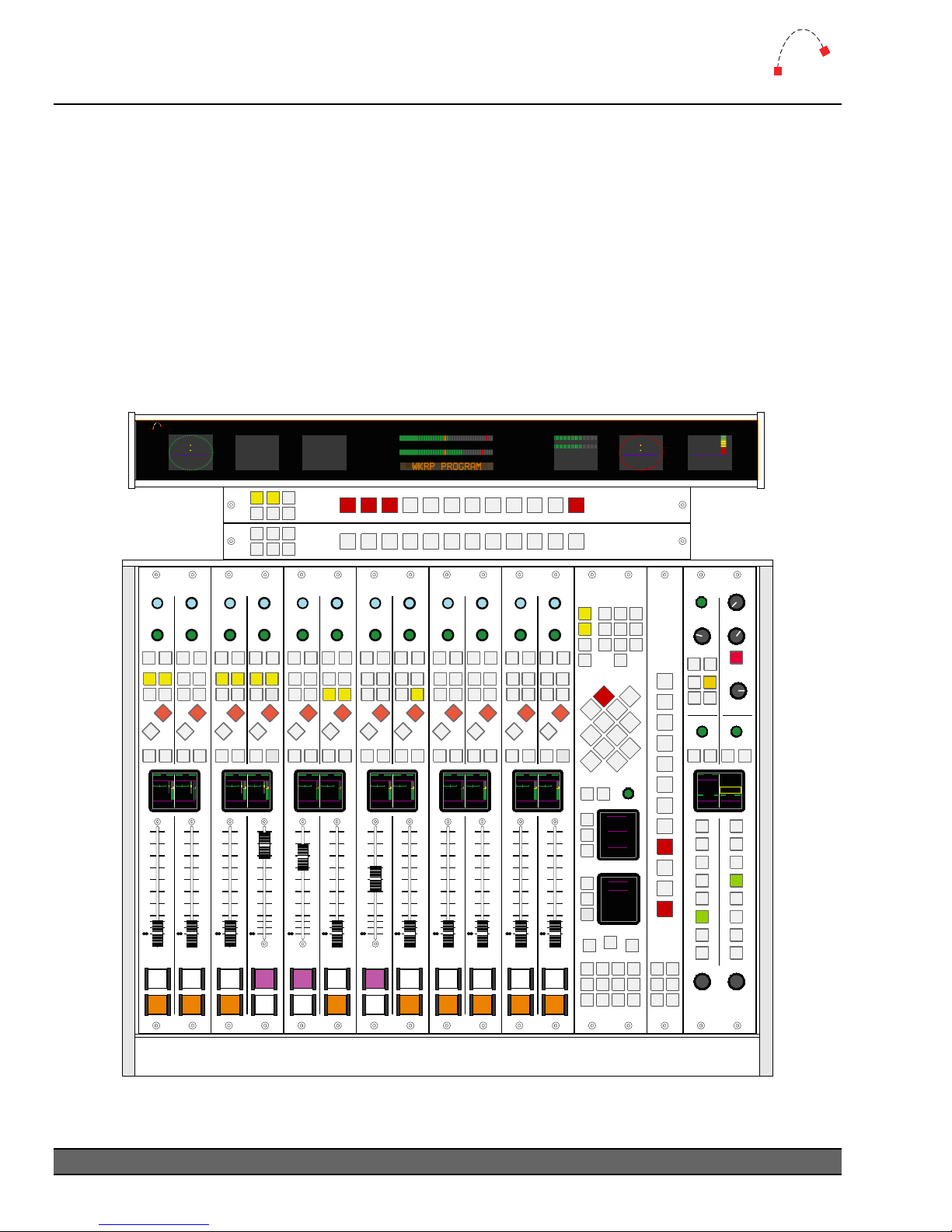
As much of the Mosaic is user-programmable, the specifics of how you use softkey functions will
depend on your existing configuration. Following is a look at each of the modules, and how the
standard functions are used.
Mosaic
Logitek
114513
WKRP Cincinatti
Studio A (StA)
SCENE: #1
Default
AM
TX-A: Studio A PST
TX-B: Studio A PST
EXCH: TX-A
ISDN: Studio A PGM
Monitor
00 03
CD 1
MLX-NSOFT MLX-NSOFT
7.0
Delay ON
MLX-FADERMLX-FADERMLX-FADERMLX-FADERMLX-FADERMLX-FADER
FUNCTION FUNCTION FUNCTION FUNCTION FUNCTI ON FUNCTION
FUNCTION FUNCTION FUNCTION FUNCTION FUNCTI ON FUNCTION
SELECT SELECT SELECT SELECT SELECT SELECTSELECT SELECT SELECT SELECT SELECT SELECT
CNG CNG CNG CNG CNG CNGCNG CNG CNG CNG CNG CNG
TAKE TAKE TAKE TAKE TAKE TAKETAKE TAKE TAKE TAKE TAKE TAKE
Ax2 Ax2 Ax2 Ax2 Ax2 Ax2Ax2 Ax2 Ax2 Ax2 Ax2 Ax2
Ax1 Ax1 Ax1 Ax1 Ax1 Ax1Ax1 Ax1 Ax1 Ax1 Ax1 Ax1
Ax4 Ax4 Ax4 Ax4 Ax4 Ax4Ax4 Ax4 Ax4 Ax4 Ax4 Ax4
Ax3 Ax3 Ax3 Ax3 Ax3 Ax3Ax3 Ax3 Ax3 Ax3 Ax3 Ax3
PGM PGM PGM PGM PGM PGMPGM PGM PGM PGM PGM PGM
IN IN IN IN IN ININ IN IN IN IN IN
CUE CUE CUE CUE CUE CUECUE CUE CUE CUE CUE CUE
TB TB TB TB TB TBTB TB TB TB TB TB
5 7 9 11 13 156 8 10 12 14 16
StAmix- StAmix-
Mono-Mode Mono-Mode Stereo-Mode Stereo-Mode Stereo-Mode Stereo-ModeMono-Mode Mono-Mode Stereo-Mode Stereo-Mode Stereo-Mode Stereo-Mode
-3-Trim -1-Trim +0- Trim +0-Trim +0- Trim +0- Trim+6-Trim +0- Trim +0- Trim +0- Trim +0- Trim +0- Trim
DYNIN DYNINDYNIN DYNIN
EQIN EQIN EQIN
StudioAPhone1 TOCISDN3 StudioA Minidisk StudioAHD1 StudioAHD3 StudioAIReplayStudioAPhone2 StudioAAudiovox TOCSAT 1 StudioAHD2 StudioA HD4 StudioA CD
StudioA TOC News StudioA StudioA StudioAStudioA StudioC StudioC StudioA StudioA StudioA
Phone1 ISDN3 Program HD1 HD3Phone2 Phone2 Program HD2 HD4 CD
10
10
5
5
0
0
5
5
10
10
20
20
30
30
40
40
50
50
60
60
ON ON ON ON ON ONON ON ON ON ON ON
OFF OFF OFF OFF OFF OFFOFF OFF OFF OFF OFF OFF
StAmix-
Traffic CityHall
10
5
0
5
10
20
30
40
50
60
StAmix-
10
5
0
5
10
20
30
40
50
60
PENDING
10
10
5
5
0
0
5
5
10
10
20
20
30
30
40
40
50
50
60
60
FCN
PromoAdsMusic1 Music2
10
5
0
5
10
20
30
40
50
60
10
10
5
0
5
10
20
30
40
50
60
10
5
5
0
0
5
5
10
10
20
20
30
30
40
40
50
50
60
60
Shortcut
10
5
0
5
10
20
30
40
50
60
READY
10
5
0
5
10
20
30
40
50
60
MLX-WSOFT
RUN
12
AUTO
4
7
Reset
Down
TIMER
CANCEL TAKE SELECT
MinidiskInput
StudioAAux2
CassetteInput
StudioAProgram
HardDiskInput
StudioAAux1
CallerAudio
StudioAMicMix
3
56
89
0
MLX-NSOFT
MLX-MON
SELECT
GAIN
LAST
TAKE
Follow
TB
Mon
GUEST/STUDIO
SELECT SELECT
LAST
TAKE
Guest
StudioAAux1
Follow
Monitor
Headphones Monitor
WKRPAIR WKRPAIR
StudioA StudioA
Program Aux2
MONO
SPLIT
Follow
Mon
EXT CUE
TB IN
MUTE
CUE
TAKELAST
Aux7
MONO
DIM
MUTE
MONITORHEADPHONE
Figure 9 - Mosaic 12 fader, Wide Softkey, Narrow Softkey, Monitor & Wide Bridge Button Riser
20
Logitek Mosaic Reference Manual
Page 23
5
Operation
Mosaic Fader Modules
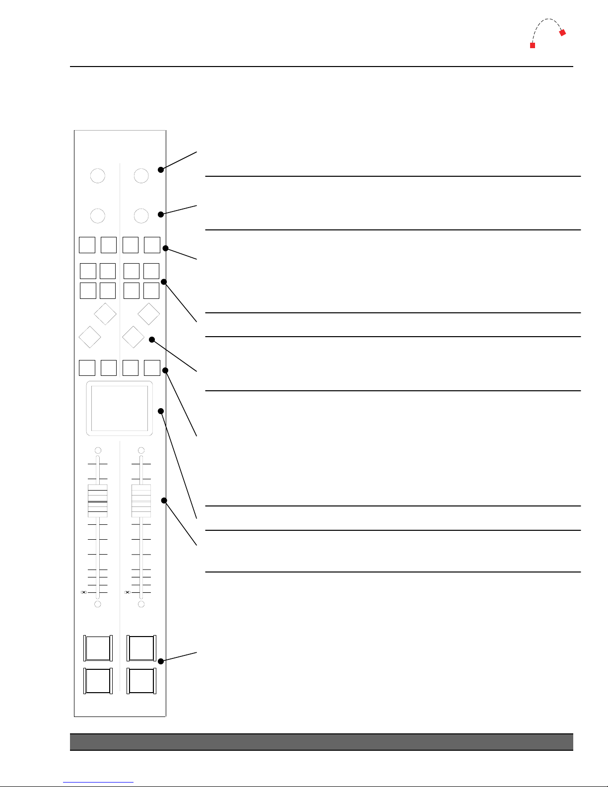
MLX-FADER (Fader Module) – International (non-UK) Layout
Use the FCN (function) wheel to select the various input functions, such a
extra Aux busses, mode, pan, trim, EQ, dynamics and Input selection. See
Mosaic screens section for details on each function.
the
Logitek
s
FCN
SEL
CNG
A1
A3
IN
TB CUE
10
5
0
5
10
20
30
40
50
60
TAKE
PGM
FCN
Use the SEL wheel to change the input selection. If you press the CNG
button first, or make a selection with the FCN wheel, the SEL wheel will
cycle through the options for that function.
SEL
CNG
TAKE
The CNG button provides access to the function selections, shown on the
screen and will automatically illuminate when a change is in progress via
A2
A1
A4
A3A2A4
the function/select wheels. Pressing the
cancel any changes in progress. The
CNG button while it is active will
TAKE button accepts an input change
to the fader and provides access to the extra menus for EQ and Dynamics.
PGM
Pressing A1, A2, A3 or A4 will assign/deassign the fader to that AUX bus.
IN
Pressing PGM will assign/deassign the fader to the main Program bus.
TB CUE
Pressing IN will toggle the fader source between the last two used inputs.
This button can also be configured to select a default input for that fader.
If the source has a return mix-minus, pressing TB sends the announcer m
to that source. Press the button momentarily to lock on, or hold it down
for push to talk. Press the
cue (PFL) bus. Press again to turn
10
5
0
5
10
20
30
40
50
60
be pre or post-fader depending on your Engine and Input configurat
“Click down” Cue @ Infinity can be enabled in your
to automatically select cue when the fader is all the way down.
See the following page for information on the Mosaic fader screen.
Moving the FADER up or down will increase or decrease respectively the
level of the assigned source. Fader range is from infinity to +10dB.
Each fader has illuminated OFF and ON push buttons for that channel.
These are used to put sources to air, in conjunction with the
CUE button to hear the input on the interna
CUE off for that fader. The cue bus may
Engine configur
PGM and
ic
l
ion.
ation
AUX mix busses. Both the OFF and ON buttons can have GPI remote
control of sources, if configured in your
ONON
In some cases, the operation of AUX busses may be configured to be
Audio Engine.
independent of the ON/OFF switch and/or the Fader gain setting.
OFFOFF
The color of the Mosaic ON/OFF buttons is software configurable, to
allow for input designation, state change, or other effects.
Mosaic v2, the ON / OFF buttons can be configured to swap positions.
In
Logitek Mosaic Reference Manual
21
Page 24
5
Operation
Logitek
MLX-FADER (Fader Module) – Screens
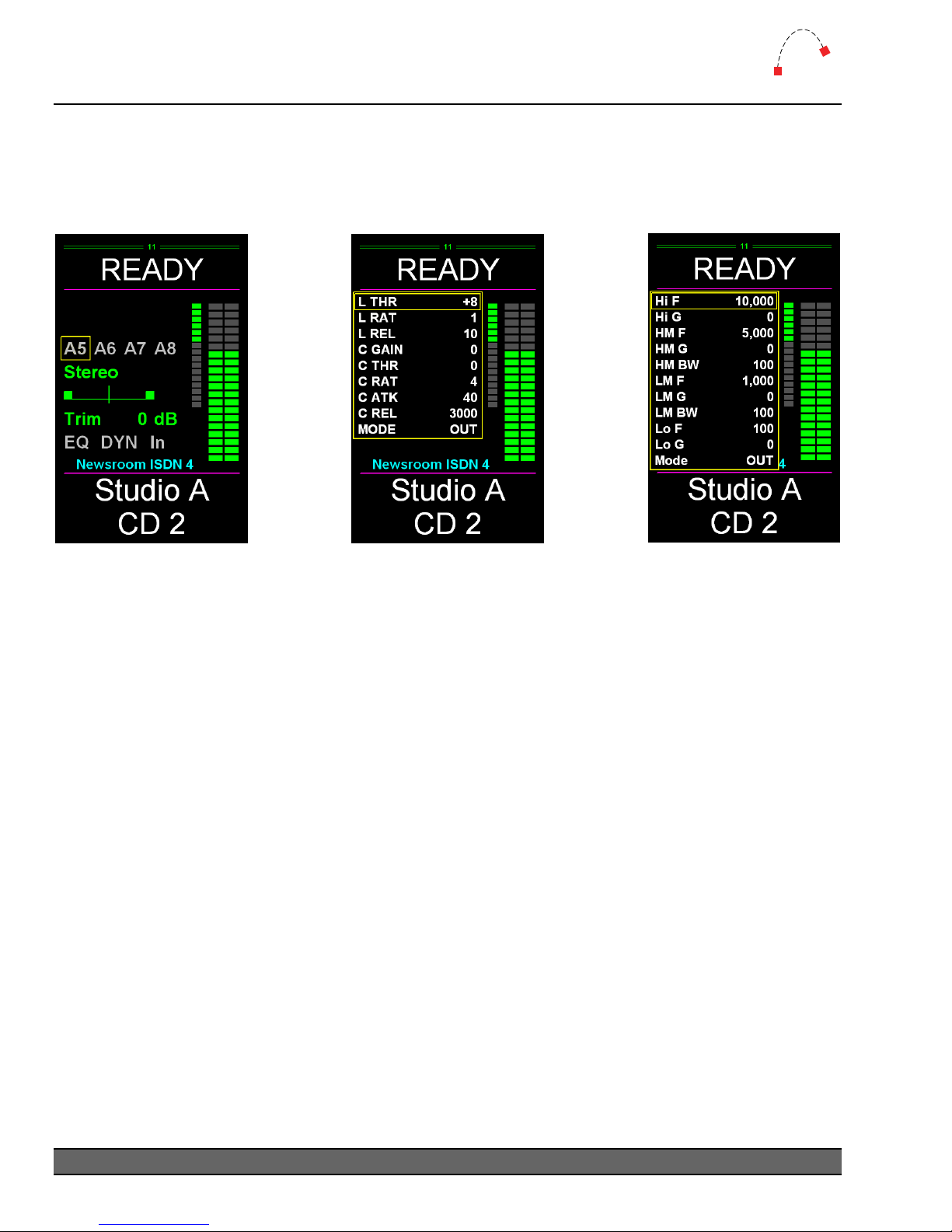
The Fader Module has an LCD color screen shared between two faders. Illustrated below is the
section for a single fader. The Mosaic is also supplied with vMosaic, a software tool which allows the
fader screen to be replicated onto a PC screen for larger display.
Figure 10 - Function Screen
Figure 11 - Dynamics
Screen
Figure 12 - EQ Screen
Fader Number
Faders are numbered from left to right starting at 01.
Alias / Label
An Alias can be assigned to a source device and will be displayed on any fader that has that source
as an input. A Label can be assigned to a specific fader or source. Both can only be a maximum of 8
characters and are displayed at the top section of the Fader Screen.
¬ See the CommandBuilder manual for more information on Aliases and Labels.
Input Meter
When a SharcAttack DSP card is fitted to the Audio Engine and is allocated to the Mosaic surface,
an input meter is provided for each fader. By default this meter is pre-fader. Using recent SA-DSP
firmware (March 2005 and later), this meter can be changed to post-fader by turning on BUS20 for
that fader. This setting can be set in the Init Trigger or changed as required in other Triggers.
Gain Reduction Meter
When a SharcAttack DSP card is fitted to the Audio Engine and is allocated to the Mosaic surface,
a gain reduction meter is provided for each fader. This meter only appears when Dynamics is
turned on for that fader, and shows the amount of gain reduction being applied by the compressor
and limiter.
22
Logitek Mosaic Reference Manual
Page 25

5
Operation
Logitek
A5, A6, A7, A8
A5 to A8 are additional AUX mix busses. These may not be available, depending on your Audio
Engine configuration. To assign or de-assign a fader to AUX5-8, use the FCN wheel to select the
appropriate mix bus, and then the SEL wheel to toggle the assignment on and off.
Mode
Use the FCN wheel to highlight the input mode. Then use the SEL wheel to move between the
options of; MONO, PHASE, LL, RR, Lx and xR. The mode is changed as you make the selection.
Press the TAKE button to accept and exit the menu. This function may not be enabled on certain
inputs, depending on your Audio Engine configuration.
Pan
After highlighting the PAN function, use the SEL wheel to move the balance left or right by winding
the wheel anticlockwise or clockwise. The source is panned as you turn the wheel. Press the TAKE
button to accept and exit the menu. This function may not be enabled on certain inputs, depending
on your Audio Engine configuration
Trim
After highlighting the TRIM function, use the SEL wheel to move the TRIM between -10 dB and
+10 dB by turning the wheel anticlockwise or clockwise. The trim level is adjusted as you turn the
wheel. Press the TAKE button to accept and exit the menu. This function is enabled on all inputs.
EQ
To edit the EQ settings for an input, use the FCN wheel to select the EQ function. Use the SEL
wheel to toggle between EQ in and out. Press the TAKE button to bring up the EQ settings menu.
Use the FCN wheel to select a parameter, and then the SEL wheel to adjust. The parameters are:
Hi F High Frequency 4,000 to 20,000 Hz
Hi G High Gain -20 to +20 dB
HM F High-mid Frequency 1,000 to 20,000 Hz
HM G High-mid Gain -20 to +20 dB
HM BW High-mid Bandwidth 10 to 4,000 Hz
LM F Low-mid Frequency 30 to 8,000 Hz
LM G Low-mid Gain -20 to +20 dB
LM BW Low-mid Bandwidth 10 to 4,000 Hz
Lo F Low frequency 30 to 1,000 Hz
Lo G Low Gain -20 to +20 dB
Mode In or Out
Press the TAKE button again to exit the menu.
Logitek Mosaic Reference Manual
23
Page 26

5
Operation
Logitek
DYN
To edit the dynamics (limiter and compressor) settings for an input, use the FCN wheel to select the
DYN function. Use the SEL wheel to toggle between dynamics in and out. Press the TAKE button to
bring up the dynamics settings menu. Use the FCN wheel to select a parameter, and then the SEL
wheel to adjust. The parameters are:
L THR Limiter Threshold -20 to +20 dB
L RAT Limiter Ratio 1 to 40
L REL Limiter Release Time 10 to 1000 mSec
C GAIN Compressor Gain 0 to 21 dB
C THR Compressor Threshold -40 to 0 dB
C RAT Compressor Ratio 1 to 40
C ATK Comp. Attack Time 5 to 68 mSec
C REL Comp. Release Time 100 to 6000 mSec
Mode In or Out
Press the TAKE button again to exit the menu.
IN
Use the IN function to select other sources that have been permitted for that fader. If only one
source has been allowed for a fader, then no list will be available. Use the FCN wheel to select the
IN function, then the SEL wheel to scroll through the list to find the source that you wish to route to
that fader. Press the TAKE button to accept the change. Press the CNG button to cancel the change.
24
Logitek Mosaic Reference Manual
Page 27
5
(
Operation
Mosaic Control Modules
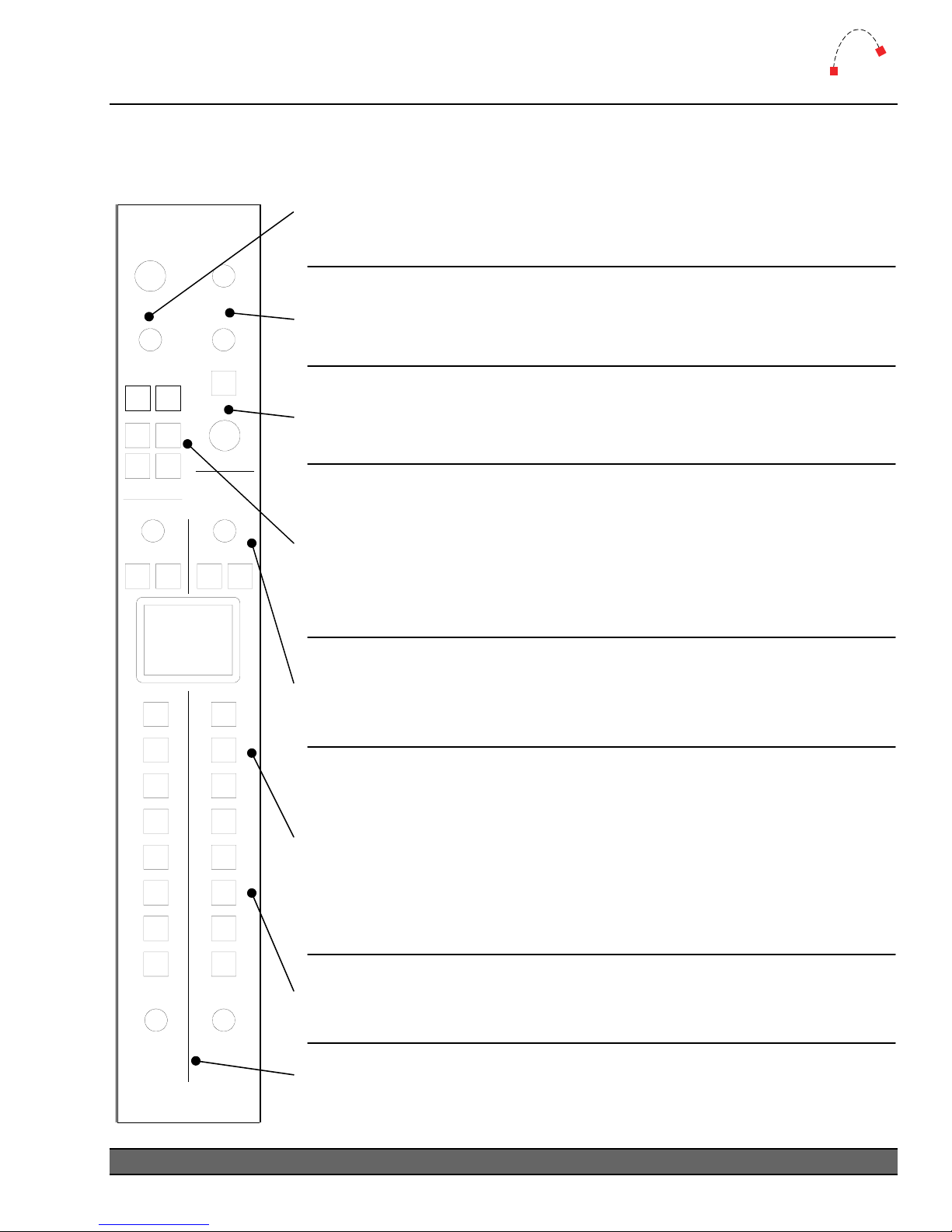
MLX-MON (Monitor Module)
Use the INPUT wheel to select the source for the Guest
Headphones/Studio send. Use the
INPUT
GAIN
LAST
TAKE
Follow
TB
Mon
IN 1
IN 2
GUEST/STUDIO
INPUT
LAST
TAKE
MONO
SPLIT
Follow
Mon
IN 1
IN 2
IN 3
IN 4
IN 5
HEADPHONES
EXT CUE
TB IN
MUTE
INPUT
LAST
MONO
MUTE
IN 1
IN 2
IN 3
IN 4
IN 5
MONITOR
CUE
DIM
TAKE
decrease
Use the EXT CUE knob to increase (clockwise) or decrease (anticlockwise)
the level of the External Cue source to the Cue bus. Use the TB IN knob to
increase (clockwise) or decrease (anticlockwise) the level of the Talkback
Return being sent to the cue/headphones/monitor channels.
Press the MUTE button to mute Talkback Return. Pressing MUTE a
second time will unmute the
Use the CUE knob to increase (clockwise) or decrease (anticlockwise) the
level going to the
Press the LAST button to toggle between the current source and the lastused source. The last source is displayed above the current source.
Use the
Use the TB toggle button to enable Talkback Return to the G
send. Turning on Follow Mon function will set the Guest/Studio s
to follow changes to the Monitor. The
programmed with “hotkey” sources, such as the
Use the INPUT wheel to select the source for the Monitor or Announcer
Headphones. Press the LAST button, to toggle between the current source
and the last-used source. Use the
selecting a source.
Press the MONO button to put the Monitor or Headphones into a mono
mix. The SPLIT button for the Headphones will enable the Split Cue mode.
When a fader is on Cue, the headphone source mixes to the left ear, and t
Cue bus is sent to the right ear. Turning on Follow Mon function will set the
Headphones source to follow changes to the Monitor. Pressing the DIM
button will turn on the Monitor Dim. Pressing the MUTE button will mute
the send to the Monitor.
muting or dim, activated by mic mute or talkback dim.
The IN1 to IN5 buttons are programmed with “hotkey” sources, such as the
PGM bus, off-air receiver, post-delay return, etc. These are programmed in
CommandBuilder, and allow direct access to commonly used sources.
Turn the HEADPHONES or MONITOR gain knobs to increase (clockwise) or
decrease (anticlockwise) the level going to the Headphones or Monitor
sends.
anticlockwise) the level to the Guest Headphone/Studio.
TAKE button to accept a change when selecting a source.
Logitek
GAIN knob to increase (clockwise) or
Talkback Return.
Mosaic’s Cue speaker, and split-cue to headphones.
uest/Studio
ource
IN1 and IN2 buttons are
PGM bus or off-air.
TAKE button to accept a change when
he
DIM and MUTE are independent of other monitor
Logitek Mosaic Reference Manual
25
Page 28
5
Operation
Logitek
MLX-MON (Monitor Module) – Screen
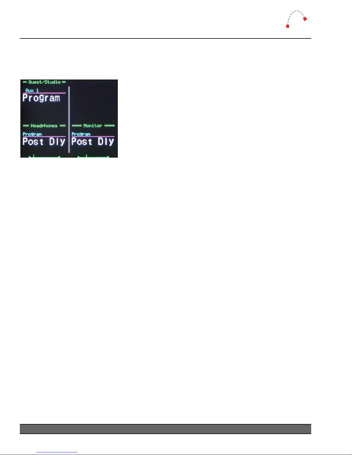
The Monitor Module has an LCD color screen which displays sources for the Guest/Studio,
Headphones and Monitor sends. Pictured below is the screen showing various sources.
Figure 13 - MLX-34 Screen
For each input, the following information is displayed.
Current Source
This is displayed in large white text, either 8 or 16 characters. In 16-character mode, the display is
across two lines (this requires a 16-character version of the Audio Engine).
Last Source
The last used input is displayed in small, light-blue text above the current input. The Last button is
used to toggle between two sources. A series of dashes indicates there is no last source.
Gain Position
The Headphones and Monitor sections of the screen contain a small bar which indicates the gain to
those sends. The Guest/Studio send has a gain pot rather than an encoder, and therefore no screen
display is required. In addition, gain to the guest headphones is more often set by a remote control
to the headphone amplifier itself.
Source List
When the Input wheel is moved, a box will appear to display the source list. Move the wheel to
scroll through the list, and use the Take button to select a source input.
26
Logitek Mosaic Reference Manual
Page 29
5
Operation
MLX-WSOFT (Wide Softkey Module)
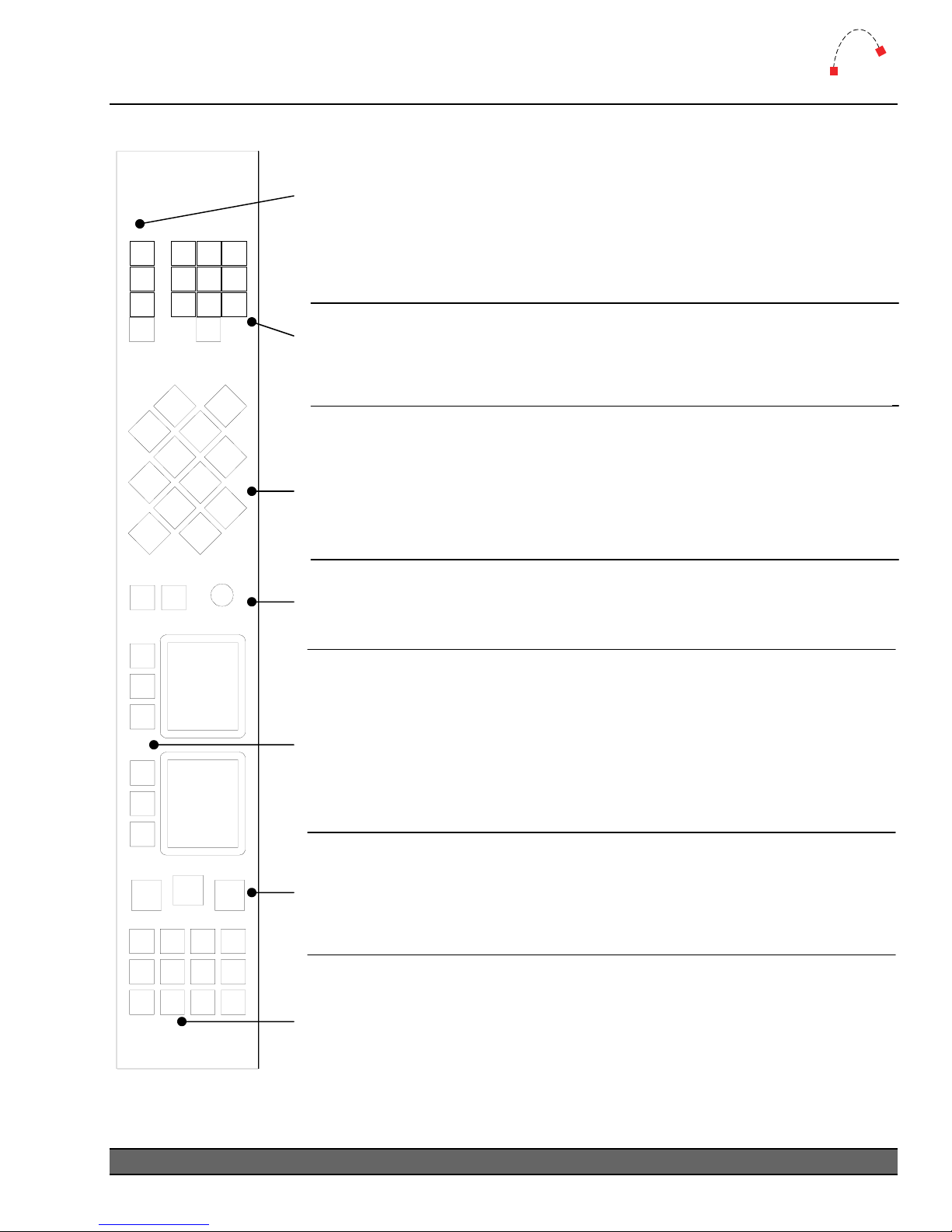
These buttons control the timer display on the Meter Bridge.
RUN is used to toggle the timer running.
AUTO mode will reset the timer each time an input is turned on (where
RUN
AUTO
RST
DOWN
TIMER
CANCEL
1
48596
7
TAKE
23
0
SELECT
that input is not set to Timer Disable in AEConfig).
RST will take the counter back to zero.
DOWN will enable the number keypad to enter a countdown time.
When the timer control is set to DOWN mode, use the numeric keypad
to enter a countdown time. To enter a time, the timer must not be
running, and must be in
unwanted time entries.
The 12 diamond buttons are programmable in CommandBuilder. Their
use will depend on your station’s requirements and setup. A common use
for these buttons is to set console “scene” layout hotkeys. They may also
be used to setup various console default settings. The lamps in the
buttons support 16 brightness levels.
The CANCEL and TAKE buttons, along with the SELECT wheel, are used
to make menu or route choices in conjunction with the two screens.
Logitek
DOWN mode. Use the RST key to clear
The two screens and six buttons are user programmable. A common use is
to setup up to six “route select” functions for making record selections or
feeding destination devices. In this case, each of the six buttons will bring
up a source selection list for that device. Use the
selection, and either TAKE to accept the source, or CANCEL to exit the
menu. Examples of the menu display are shown on the following page.
SELECT wheel to make a
These 3 Softkeys are programmable through CommandBuilder. Possible
uses include announcer mic mute, post-delay monitoring swap, or other
control. The lamps in the buttons support 16 brightness levels.
These 12 Softkeys are programmable through CommandBuilder. A
common usage is as intercom buttons. The lamps in the buttons support
16 brightness levels.
¬ Refer to the Com ons. mandBuilder manual for information on programming functi
Logitek Mosaic Reference Manual
27
Page 30
5
Operation
Logitek
MLX-WSOFT (Wide Softkey Module) – Screens
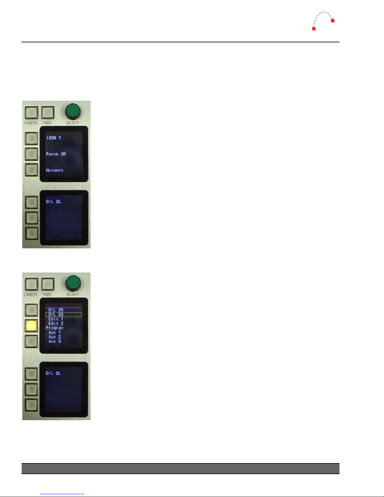
The Wide Softkey Module has two LCD color screens, which are used to display user-defined text.
Pictured below are the screens showing the Route Select function, which is programmed with the
CommandBuilder scripting application.
Pictured are the screens showing the normal operation of the Route Select
mode.
The text next to each button shows the currently routed source for that
particular destination.
It is possible to use only one screen for Route Selections, and another for
showing other text or menu selections.
Figure 14 - Route Select
normal
To change a Route Select, press the button for the destination you wish to
change. The lamp will light, and a list of sources will be displayed on the top
screen. Use the SELECT wheel to make a selection, and TAKE to accept the
choice. Use CANCEL to exit the menu without making a change.
When a route is made, the source name will be displayed next to the
button.
To use the Route Select function, you will need to setup the appropriate
outputs and allowed sources in AEConfig. You will then need Route Select
Triggers programmed in CommandBuilder. The CommandBuilder manual
includes examples of how to write these Triggers.
Figure 15 - Route Select
choice list
28
Logitek Mosaic Reference Manual
Page 31
5
Operation
MLX-NSOFT (Narrow Softkey Module)
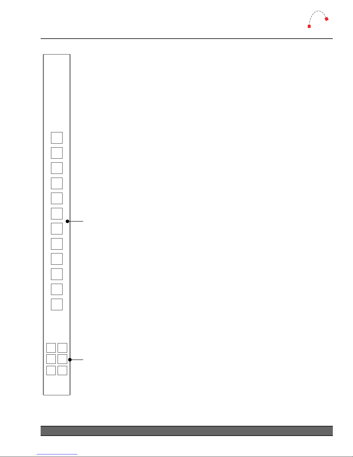
This module is totally configurable and has no default operation. It is programmed using
Triggers in CommandBuilder. Refer to the CommandBuilder manual for more
information on programming Triggers for these buttons.
Logitek
These 12 keys are programmable through CommandBuilder. Possible uses
include delay control (on, off, dump), remote record start/stop & tally,
quick record, and other miscellaneous control functions. The lamps in the
support 16 brightness levels. buttons
These 6 Softkeys are programmable through CommandBuilder. Possible
clude additional intercom buttons (eg for outside souses in urces,
orderwire lines, etc), or to show status information from external GPIs (eg
program fail). The lamps in the buttons support 16 brightness levels.
Logitek Mosaic Reference Manual
29
Page 32
6
Maintenance
Logitek
6 Mai
The Mosaic
console is no at can be performed by
suitably qualified te
ntenance
uses multi-layer boards with surface mount technology. As such, the majority of the
t user-serviceable. However, there are some basic tasks th
chnical personnel.
Warranty
Logitek Electronic Systems will honor the warranty of the system when conducting field
maintenanc
¾ Repairs or updates only relate to recommended and documented procedures
¾ Care is taken and procedures are followed
¾ Repairs are conducted by suitably trained or experienced service personnel
If you do not feel comfortable performing maintenance or repairs, please do not proceed. If you
would like advice prior to attempting a repair, please contact Logitek Electronic Systems or your
reseller.
e, provided:
Firmware Updates
Each module str ems or your
value-added res fix
bugs. A list of fir dix A.
Each module type has specific firmware that only runs on that module. When fitting updated
firmware ROMs, take care to use the correct chip for that module. Firmware chips are labeled with
the module code, version and date.
A PLCC extractor tool is recommended for removing ROMs. Due to the physical layout of the
Mosaic modules, you may only be able to extract the ROM from one side at a time (depending on
the size/profile of the extractor tool). Take care to not bend the pins of the chip when removing it.
ip has a firmware chip that is field upgradeable. Logitek Electronic Syst
eller may from time-to-time supply firmware updates to add new features or
mware versions is contained in Appen
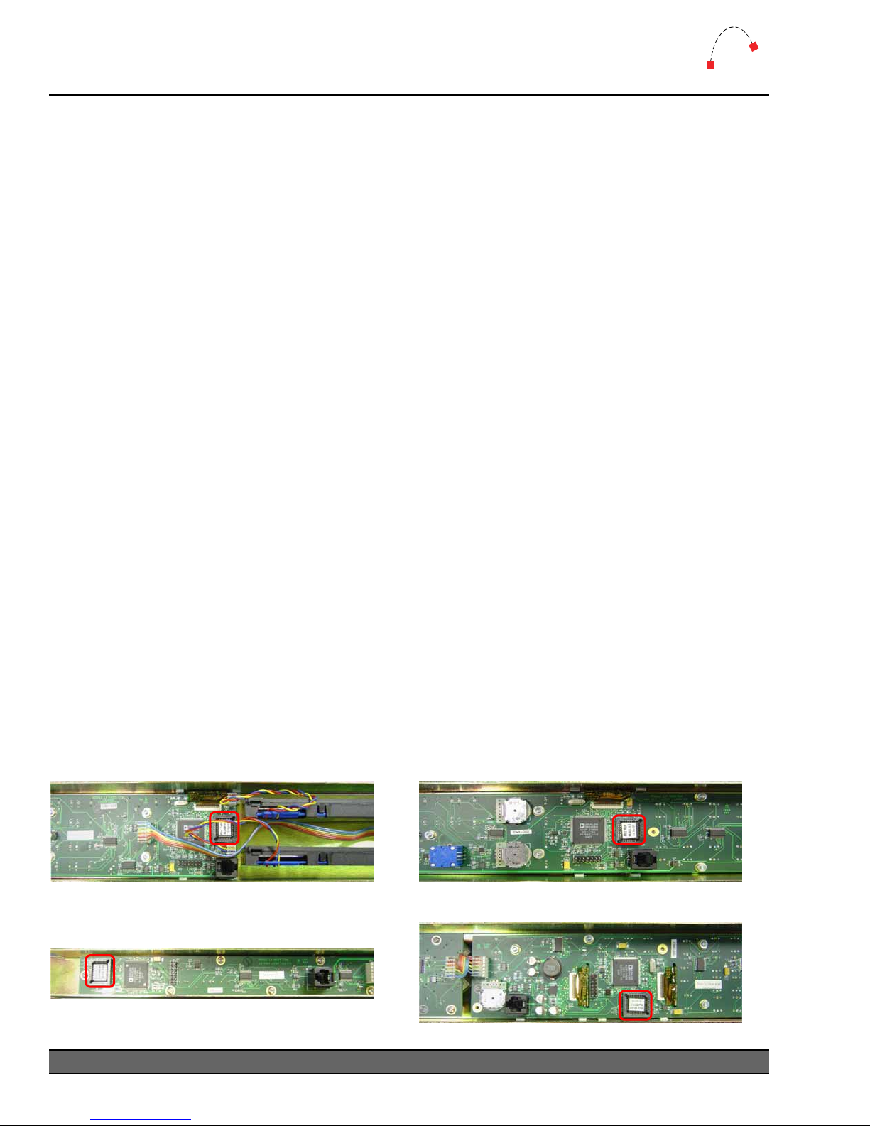
Figure 17 - Fader Module underside
Figure 18 - Narrow Softkey Module underside
30
Logitek Mosaic Reference Manual
Figure 16 - Wide Softkey Module underside
Figure 19 - Monitor Module underside
Page 33
6
Maintenance
Logitek
Tools Required
¾ Hex/Allen Key –1/16” and 3/32” (As of Mid May 2005 a tool is provided with each surface)
¾ PLCC Extractor tool
Procedure
It is not essential
individual modu
1. Remove the two o
2. Carefully remove the module from the frame.
3. Disconnect the COM cable from the RJ11 connector.
4. Use the PLCC extractor to carefully remove
extractor used, you may only be able to use one side of the tool – if so, exerc
the pins are not bent.
5. Insert the new ROM chip by lining up the notch on the top-left of the chip and gently
pressing it in.
6. Re
7. Replace the module in t
In addition to the module strips, the Power Supply Unit and Meter Bridge also contain a ROM chip.
The replacement procedure is the same, except for the panel removal.
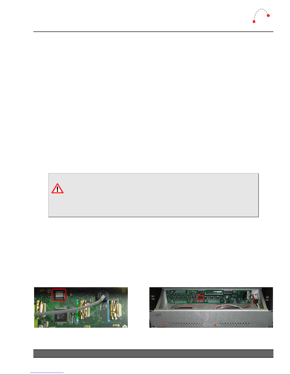
¾ The Power Supply Unit ROM is accessed by removing the top lid of the box. To prevent
¾ The Meter Bridge ROM is accessed by removing the rear panel of the bridge. Take care not
Picture – PSU ROM
connect the module COM cable.
Anti-static precautions should be taken when replacing firmware chips.
In addition, care should be taken with the module components to ensure no
damage and because this unit contains live mains, disconnect from mains before removing
the lid.
to damage the screws when removi
that the Mosaic be completely powered off during a ROM upgrade, however, the
le should be disconnected before removing the chip.
r four hex screws from the required module.
the existing ROM chip. Depending on the
ise caution so
he frame, and screw it back in.
damage is done.
ng this panel.
Picture – Meter Bridge ROM
Figure 21 - Meter Bridge inside Figure 20 - PSU inside
Logitek Mosaic Reference Manual
31
Page 34
6
Maintenance
Co
mponent Replacement
The ins commonly used physical components, including faders and switches,
Mosaic spares kit conta
hich can be replaced by station technicians.
w
Logitek
Fader Replacement
The Mosaic uses a Penny & Giles digital fader:
Mo
del No PFG8110/D/U----/A
Spe
c No D468111
No a
audio is carried through the fader, just control signals. The fader can be easily replaced with
spare f
rom the spares kit, or an electronics supplier.
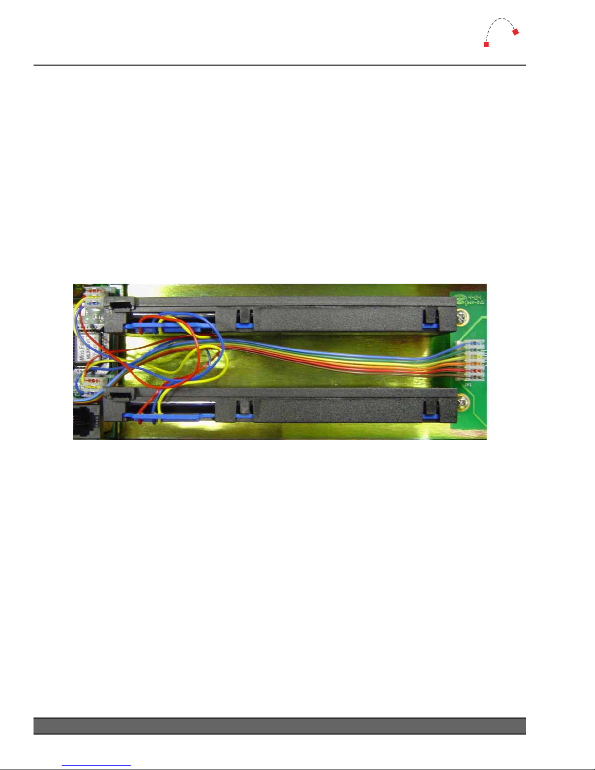
Figure 22 - Faders from underside of module
To replace a fader:
1. Remove the four hex screws from the required module.
2. Carefully remove the module from the frame.
3.
Disconnect the fader from the main board.
Remove4. the slider cap.
5. Remove the two hex screws that mount the fader to the module.
6. two hew screws.
Fit the replacement fader to the module using the
7. Replace the slider cap.
8. Reconnect the fader connector, ensuring the same polarity as the other fader on the module.
9. Replace the m ame, and screw it back in.
odule in the fr
32
Logitek Mosaic Reference Manual
Page 35

6
Maintenance
Logitek
Module swap-out
If you need to swap a module with an on-site spare, you can simply unscrew the module,
disconnect it, connect the replacement and screw it in. Modules are fully hot-swappable – they will
refresh their status shortly after powering up.
Softkey Button LED R
The small Mosaic buttons used for bus assignme
metimes be subject to movement by the button shell. In some cases, the LED may become
so
dislodged from the PCB below.
It is possible to conduct field repairs to re-solder the LEDs to the PCB. However, this requires
removing the knob caps, screen connectors and boards. This procedure can be delicate and time
consuming. Please contact Logitek Electronic System
is procedure. In many cases it may be easier to arrange replacement modules or boards rather
th
than attempt a field repair.
epair
nts and Softkeys contain an LED which can
s or your reseller for advice before conducting
More Assistance
If you would like more assistance with maintenance and service, please contact Logitek Electronic
Systems or your reseller.
You can also post questions and review other users’ experiences at the Logitek support forum. See
www.logitekaudio.com
and follow the links to Tech Support Forum.
Logitek Mosaic Reference Manual
33
Page 36

Appendix A
Release Notes
Appendix A Release Notes
What’s New
ew Features in Mosaic v2.0
N
Logitek
¾ Fader On/Off button fu
¾ Fader On/Off RGB lamp colors improved by turning off LEDs when color value is zer
¾ Fader On/Off lamps now support three flash rates – slow, medium & fast.
¾ Fader Bus Assignments can now be locked individually to prevent accidental change.
¾ Fader PGM Lock from AE
¾ Fader levels stabilized to prevent Supervisor logging continuous level changes.
¾ Fader IN buttons can now be assigned default routes.
¾ Fader Aux button lamps are now dim when channel is off, unless independent bus switching
is in use.
¾ Meter Bridge feature screen locations are now configurable.
¾ Meter Bridge fixes fo
¾ Meter Bridge Timer, Clock & Delay locations now configurable.
¾ Meter Bridg
¾ Meter Bridge now supports 6 x Horizontal LCD Meters for showing AUX / CUE bus level.
¾ Meter Bridge impr
¾ Meter Bridge Delay display now clears after an Audio Engine reset (where delay is emptied).
¾ Monitor Hotkey buttons can now be assigned default routes and do not require Triggers.
¾ Monitor LAST buttons can now be assigned default routes.
¾ Monitor Follow Mon
¾ Monitor Fader levels stabilized to prevent Supervisor logging continuous level changes.
¾ Monitor module fixes for 16 character mode.
¾ Narrow Softkey module now supports the number of flashes command.
¾ PSU COM Port to Device Number Map is now configurable.
¾ PSU COM Port Map and Bridge feature locations are now saved in non-volatile memory.
¾ PSU module bug fixes.
¾ PSU module increased capacity for device names and tick marks.
¾ Wide Softkey module now supports the number of flashes command.
¾ Wide Softkey Timer button controls are now sent to Supervisor.
The Mosaic v2.x firmware also includes many minor bug fixes and improvements to the way text is
displayed on screens. As such, the 2.x update is highly recommended for any 1.x users.
e now supports 2 x Timers with small & large mode.
nction can be reversed so ON button is at bottom.
o.
Config is now honored.
r 16 Character mode on Timer auto-reset.
ovements and bug fixes to seconds display on large Clock & Timer.
status now sent to Supervisor as BUS15.
34
Logitek Mosaic Reference Manual
Page 37
Appendix A
Release Notes
Upgrade Strategies
Logitek
Upgrading from M
Mosaic v2.x firmware
critical issues are expected in doin
Ple
ase observe the following considerations, which may affect your upgrade:
¾ All modules should be upgraded to v2.x – including PSU and Meter Bridge.
¾ The Meter Bridge screen locations are now progra
commands). The default in v2.x firmware is to show these screens in the same l
their positions in v1.x firmware.
¾ The RGB color command format for the Fader On/Off lamps has changed to add support for
a flashing
need to be changed. If updating
CommandBuilder with the new
Systems or your reseller.
¾ The COM Port to Device Number map is now configurable. See p
Device Numbers.
Cu
rrent Versions
osaic v1.x to v2.x
is designed to retain compatibility with existing v1.x systems. As such, no
g a straight firmware upgrade from v1.x to v2.x.
mmable (see Appendix E for protocol
lamp. As such, any
ASM or MOSAIC COLOR commands in CommandBuilder will
ASM commands, see Append
B1 command format, please con
ix E. For a new version of
tact Logitek Electronic
age 18 for a list of default
ocation as
Follow
Mod
MLX-400 (Fader) January 2005 2.11 Mosaic v2 Public Release
MLX Public Release -407 (Wide Softkey) November 2005 2.1 Mosaic v2
MLX-408 (Narr Softkey) November 2005 2.1 Mosaic v2 Public Release
MLX-410 (PSU) January 2005 2.11 Mosaic v2 Public Release
MLX-411 (Monitor) November 2005 2.1 Mosaic v2 Public Release
MLX-412 (Bridge) November 2005 2.1 Mosaic v2 Public Release
Thi b
ing are the currently released firmware versions of the Mosaic surface.
ule Date Version Notes
s ta le was last updated 13-Jan-2005.
TIP: Mosaic Monitor mute, Ext Cue gain, TB In gain and TB M
DSP v3.60 (June 2005) or later. On prior versions, these functions will not work
correctly, and the Ext Cue gain and TB In gain will affect monitor/headphones dim
amounts instead of the intended function.
TIP: Additional Mosaic AUX / CUE meters requires SharcAttack DSP v3.63 (November
2005) or later, and either AE-C6 v3.63 or AE-C2 v3.25 (November 2005) or later.
ute require SharcAttack
Logitek Mosaic Reference Manual
35
Page 38
Appendix A
Release Notes
Logitek
Version History
The first public release of Mosaic v1.x firmware was in April 2005. In November 2005, v2.x
firmware was released to add new features and fix minor issues in the previous versions. The
following release notes detail the additions and fixes to each module in the Mosaic.
MLX-400 (Fader Module)
ersion Date Notes
V
1.8 May 2005 v1.x Public Release
2.0
2.1
2.11 January 2005 Fixed bug where the right hand CNG button could cancel after 1 second instead of 60
November 2005 v2.x Beta Release
Added BUS37 mode switch for IN button (OFF = last input mode / ON = default input mode)
Added AE command type 61 to set default route for IN button when in default input mode
Added AUX bus lo
Timer Reset command is now also sent to Audio Engine using AE command type 64
Fader levels are stabilized when sitting on threshold between two levels
Fader module honors the PGM Lock setting from AEConfig (preventing PGM/Route/IN button)
November 2005 v2.x Public Release
Added reference marker to input meter
Changed B1 intensity command so that RGB values are first 3 x 4 bits, with last 4 bits flash rate
Added su
Improved display of colors so that RGB LEDs turn off when color value is zero (intensifies others)
Added AE command to allow ON/OFF button function to be reversed (ON button at bottom)
Chang
Aux buttons now dim when main button is off, unless independent aux switching is active
Fixe
pport for flash rate of ON/OFF buttons – slow, medium or fast
e buttons will now automatically timeout after 30 seconds
d issue with ON/OFF button color command lamps could flash unexpectedly
ckout switch using BUS38-46 (AUX1-8). When on, surface AUX is disabled
MLX-407 (Wide Softkey Module)
Version Date Notes
1.6 April 2005 v1.x Public Release
2.0 November 2005 le
2.1 November 2005 v2.x Public Release
v2.x Beta Reppase
Added su t for sp
Timer contro butto ow also sent to Supervisor
or ecifie mand
l s are n as AE commands
MLX-408 (Narrow Softkey Module)
Version Date Notes
1.4 rch Ma 2005 v1.x Public Release
2.0 November 2005 v2.x Beta Release
Added support for specified number of flashes in B1 flash command
2.1 Novem
ber 2005 v2.x Public Release
Fixed issue with Intensity B1 command inc
d number of flashes in B1 flash com
n
orrectly turning on or flashing lamps
36
Logitek Mosaic Reference Manual
Page 39
Appendix A
Release Notes
Logitek
MLX-410 (Power Supply / Comms)
Version Date Notes
1.6 /
1.6b
2.0 November 2005 v2.x Beta Release
2.1 November 2005 v2.x Public Release
2.11 January 2005 Fixed bug that could cause the surface to lockup when powered on or module connected
ML 1 (Monitor M ule)
Version Date
1.3 March 2005 v1.x Public Release
2.0 November 2005
2.1 November 2005 v2.x Public Release
April 2005 v1.x Public Release
Increased number of supported source names to 700
Increased number of supported tick marks to 2000
Fixed issue with name lookup procedure
ntry code now sent to all modules
Cou
Independent bu
COM port / device map can no
Added COM port m
Added support for v2.1 command set for other modules
Save Fader On/Off swap mode to non-volatile memory
Changes to default COM Port to Device Address Map (see table on page 18
X-41 od
Notes
v2.x Beta Release
Added BUS37 switch for LAST button (OFF = last input mode / ON = default input mode)
Added AE command type 61 to set default route for IN button wh
Added BUS15 switch/status for Follow Monitor mode on Headphones & Guest/Studio
Fader levels are stabilized when sitting on threshold between two levels
Fixed issues with Follow Monitor routing and status in 16 character mode
s switch state now sent to all modules
w be changed from commands sent from Supervisor
ap and meter bridge feature locations to non-volatile memory
en in default input mode
MLX-412 (Meter Bridge)
Version Date Notes
1.5 April 2005 v1.x Public Release
2.0 November 2005
2.1 November 2005 v2.x Public Release
v2.x Beta Release
Added support for timer to be controlled from Supervisor with AE type 6
Added support for se
Added support for small timer mode (no seconds oval)
Locations for Timer, Clock, Meters and Delay time now settable with AE commands
Added support for
Improved seconds oval on clock
Fixed bug in second
All 16 characters of s
Restored default position of clock to screen 1 of Wide Meter Bridge
Fixed problem where delay time display does not always update correctly
Delay display is now erased after an Engine is reset (causing delay to be emptied)
Fixed issue with timer running slow
Fixes issue with components not erasing prior locations when moved to new location
4 commands
cond timer
six horizontal meters on chan35-40
s and timers
s oval when changing from down to up mode
ource name are now shown in timer when in auto mode
Logitek Mosaic Reference Manual
37
Page 40
Appendix A
Release Notes
Logitek
Known Issues
follo es have nd are under investigation.
The wing issu been reported a
Mosaic v1.x
Module Issue Descr Resolution / Workaround
MLX-400 (Fader) When the IN command is sent
from the sur
effects on o
MLX-410 (PSU) GPI Output v1.6b or later #7 sticks on after a pulse (A2) command is sent. Upgrade to MLX-410
MLX-411 ( hara or module does not update the 2nd
MLX-411 ( 6 Chara
LX-412 (Bridge) In 16 Character mode, the Meter Bridge does not show the 2nd line of Upgrade to MLX-412 v2.0 or later M
MLX-412 (Bridge) LCD meter display right channel middle segment does not overhang Firmware update in development
Monitor) In 16 C cter mode, the Monit
line of the D w
Mon mode.
for the Hea
the Device Name on the Timer when auto-reset is used.
This tabl ted in 5. There will be no further updates to Mosaic v1.x.
e was upda November 200
iption
button is pressed, a phantom Bus On
face after the route is made. This may have undesirable
ther functionality.
evice Name for the Headphones or Studio/Guest in Follo
dphones or Studio/Guest in Follow Mon mode.
Upgrade to MLX-400 v1.8 or later
Upgrade to MLX-411 v2.0 or later
r later Monitor) In 1 cter mode, the Monitor module does not perform the route Upgrade to MLX-411 v2.0 o
Mosaic v2.x
Module Issue Descr d
MLX-400 (Fader) Sending a M
ON bu
be steady. This
MLX-408 (NarrSoft) Intensity B1 command causes lamps to turn on or flash in MLX-407 Upgrade to MLX-408 v2.1 or later
v2.0
MLX-412 (Bridge) Mosaic clock display defaults to screen 2 instead of 1 in MLX-412 v2.0 Upgrade to MLX-412 v2.1 or later
MLX-412 ( Delay displa LX-412 v2.0 Upgrade to MLX-412 v2.1 or later Bridge) y freezes during count up in M
MLX-412 ( som X-412 v1.x / 2.0 Upgrade to MLX-412 v2.1 or later Bridge) Timers etimes run slow in ML
MLX-412 ( reenBridge) LCD sc s do not always boot up correctly Resolution in progress
MLX-412 (Bridge) LCD meter
when using ion)
MLX-412 (Bridge) After issuing velopment clear NV-RAM command, clock will not run until reset Firmware update in de
This table was updated in January 2005.
iption Resolution / Workaroun
OSAIC COLOR B1 command to the top button (default
tton) ll cause it to flash when it should
when it is illuminated wi
affects MLX-400 v2.1 Beta versions only.
default meter setting (OK when setting exact meter locat
Upgrade to
MLX-400 v2.1 or later
elopment display right channel middle segment does not overhang Firmware update in dev
38
Logitek Mosaic Reference Manual
Page 41

Appendix B
Specifications
Appendix B Specifications
Mosaic Frames
Logitek
MLX-F10 (10
Dimens .4” W x 18.4” D
ions 14 (365 mm x 467 mm)
MLX-F17 (17 sl
Dimensions .2” W x 18.4” D (616 mm x 467 mm)
slot frame)
ot frame)
24
MLX-F24 (24 slot frame)
Dimensions 3 .0” W x 18.4” D (864 mm x 467 mm)
MLX-F32 (32 ot frame)
imensions 45.2” W x 18.4” D (1148 mm x 467 mm)
D
Mosaic M
Fader
Width lots
No of faders 2
Features The Fader Module provides the following features:
Module
4
sl
odules
2 s
RGB-illuminated on/off and control start/stop buttons
P
enny & Giles® conductive plastic faders
D put selection a
edicated controls for six bus assigns, default in nd talkback insertion
L ow access to the input r mode
CD screen and two rotary controls all outer control, input
c gns,
ontrol, input trim level, pan/balance control, aux bus assi
d
ynamics processor
C 16-c
olor LCD screen also displays input meters and the 8 or haracter source name
Available in standard (International) or U.K. configurations
4-band equalizer and
Monitor Module
Width 2 slots
Features The Monitor Module provides the following features:
Contains controls for main monitor, cue speaker, operator headphone, guest headphone
and talkback level
Monitor and Operator Headphones have 5 input select hotkey buttons
Guest has 2 input select hotkey buttons
Guest and Operator Headphones can be set to follow the monitor source selection
All three sections have direct access to the input router
The full color LCD screen displays the 8 or 16-character source names
Available in standard (International) or U.K. configurations
Logitek Mosaic Reference Manual
39
Page 42

Appendix B
Specifications
Narrow Softkey Module
Width 1 slot
Features The Narrow
12 program
6 programma
Solid illumination or three different flash speed
Each programmable button can be set to
Softkey Module provides the following features:
mable buttons with red illumination
ble buttons with yellow illumination
s
one of 16 brightness levels
Wide Softkey Module
Width 2 slots
eatures The Wide Softkey Module provides the following features:
F
12 programm
21 programmable buttons with yellow b
Solid illumination or three different flash speed
Each programma
Timer control
Two full color LCD screens that display re
able buttons with red backlighting
acklighting
s
ble button can be set to one of 16 brightness levels
s
cord router information as well as user text
Logitek
Meter Bridges
Narrow Meter Bridge
Dimensions 13
Features The Narrow Me
Wide Meter
Dimensions 2
Features
” W x 3.8” H x 2.6” D (330 mm x 97 mm x 66 mm)
ter Bridge provides the following features:
-LED stereo bar graph meter, tri-color LEDs simultaneously showing peak and VU levels
40
16 character LED display shows meter source or p
Two full color backlit LCD screens can be user programme
clock, up/down timer, talk delay operation
, user text or user graphics
rogrammable text
d to display auxiliary bus meters,
Bridge
3.7” W x 3.8” H x 2.6” D (602 mm x 97 mm x 66 mm)
e Wide Meter BridgeTh provides the following features:
sly showing peak and VU levels 40-LED stereo bar graph meter, tri-color LEDs simultaneou
16 character LED display shows meter source or programm
Six full color backlit LCD screens can be user programmed to display auxiliary bus meters,
k, up/down timer, talk delay operation, user text or user graphics
cloc
able text
Mosaic Power Supply
Dimensions
Voltage
Frequency
Consumption
Connections gine
Interfaces
19” W x 3.5” H x 7” D (483 mm x 89 mm x 178 mm)
110 - 230 VAC, automatically selected
50/60 Hz
65 W
d outputs, 1 RJ45 for Audio En2 ports for connection to surface, 2 ports for GPI inputs an
Includes 25 switch closure inputs and 25 relay outputs
40
Logitek Mosaic Reference Manual
Page 43
Appendix C
Pinouts
Appendix C Pinouts
Logitek
To Au Engine
Connection to ted on the rear of the Power Supply
Unit. When c ling can be used.
dio
the Audio Engine is via a RJ45 connector moun
onnecting to an AE-C6 Controller Card, straight through CAT5 cab
in Connection
P
1 Cue -
2 Cue +
3 RS485 RX-
4 RS4 85 TX-
5 RS485 TX+
6 RS485 RX+
7 No connect
8 Ground
GPIs
GPI connections are on 25-pair Centronics Telco
style (or similar) termina
tion blocks.
GPI Inputs GPI Outputs
1 GPI I 26 Ground n 1
2 GPI In
3 GPI In 3
4 GPI In 4
5 GPI In 5
6 GPI In 6
7
8 GPI In 8 33 Ground
9 GPI In 9 34 Ground
10 GPI In 10 35 Ground 10 GPI Out 10 35 GPI Out 10
11 GPI In 36 Ground 11 11 GPI Out 11 36 GPI Out 11
12 GPI In 12 37 Ground
13 GPI In 13
14 GPI In 14 39 Ground
15 GPI In 15
16 GPI In 16
17 GPI In 17 42 Ground
18 GPI In 18 43 Ground
19 GPI In 19 44 Ground
20 GPI In 20 45 Ground
21 GPI In 21 46 Ground
22 GPI 47 Ground In 22
23 GPI In 23 48 Ground
24 GPI In 24 49 Ground
25 GPI In 25 50 Ground 25 GPI Out 25 50 GPI Out 25
2 27 Ground
28 Ground
29 Ground
30 Ground
GPI In 7 32 Ground
40 Ground
41 Ground
cables. We recommend terminating GPIs to Krone
ion Pin Connection Pin Connection Pin Connection Pin Connect
1 GPI Out 1 26 GPI Out 1
2 GPI Out 2 27 GPI Out 2
3 GPI Out 3 28 GPI Out 3
4 GPI Out 4 29 GPI Out 4
5 GPI Out 5 30 GPI Out 5
6 GPI Out 6 31 GPI31 Ground
7 GPI Out 7 32 GPI Out 7
8 GPI Out 8 33 GPI Out 8
9 GPI Out 9 34 GPI Out 9
12 GPI Out 12 37 GPI Out 12
13 GPI Out 13 38 GPI Out 13 38 Ground
14 GPI Out 14 39 GPI Out 14
15 GPI Out 15 40 GPI Out 15
16 GPI Out 16 41 GPI Out 16
17 GPI Out 17 42 GPI Out 17
18 GPI Out 18 43 GPI Out 18
19 GPI Out 19 44 GPI Out 19
20 GPI Out 20 45 GPI Out 20
21 GPI Ou t 21 46 GPI Out 21
22 GPI Out 22 47 GPI Out 22
23 GPI Out 23 48 GPI Out 23
24 GPI Out 24 49 GPI Out 24
Out 6
Logitek Mosaic Reference Manual
41
Page 44
Appendix C
Pinouts
To Surface
Logitek
Connection from Mosaic PS
need to make your own cab
U to Surface is via one or two 25-pair cables. Generally, there is no
les. However, the pinouts are shown for reference.
Surface A
in Connection Pin Connection
P
1 TX 1 26 +24V
2 RX 1 27 Ground
3 TX 2 28 +24V
4 RX 2 29 Ground
5 TX 3 30 +24V
6 RX 3 31 Ground
7 TX 4 32 +24V
8 RX 4 33 Ground
9 TX 5 34 +24V
10 RX 5 35 Ground
11 TX 6 36 +24V
12 RX 6 37 Ground
13 TX 7 38 +24V
14 RX 7 39 Ground
15 TX 8 40 +24V
16 RX 8 41 Ground
17 TX 9 42 +24V
18 RX 9 43 Ground
19 TX 10 44 +24V
20 RX 10 45 Ground
21 TX 11 46 +24V
22 RX 11 47 Ground
23 TX 12 48 +24V
24 RX 12 49 Ground
25 - + Cue Spkr 50 Cue Spkr
Surface B
Pin Connection Pin Connection
1 TX 13 26 +24V
2 RX 13 27 Ground
3 TX 14 28 +24V
4 RX 14 29 Ground
5 TX 15 30 +24V
6 RX 15 31 Ground
7 TX 16 32 +24V
8 RX 16 33 Ground
9 TX 17 34 +24V
10 RX 17 35 Ground
11 TX 18 36 +24V
12 RX 18 37 Ground
13 TX 19 38 +24V
14 RX 19 39 Ground
15 TX 20 40 +24V
16 RX 20 41 Ground
17 TX 21 42 +24V
18 RX 21 43 Ground
19 TX 22 44 +24V
20 RX 22 45 Ground
21 TX 23 46 +24V
22 RX 23 47 Ground
23 No connect 48 No connect
24 No connect 49 No connect
25 No connect 50 No connect
42
Logitek Mosaic Reference Manual
Page 45

Appendix D
Spares Kit
Appendix D Spares Kit
A spares kit is available from Logitek Electronic Systems.
This kit contains mechanical parts that may need to be replaced in the life of a c
Logitek
onsole.
Conten
e Mosaic spares kit contains the following:
Th
¾ Cue ga ot nitor module
1 x in p for mo
¾ Large s ey le switch
1 x oftk modu
¾ Fader O O h
1 x n/ ff switc
¾ Small f r & y module switch
2 x ade softke
¾ Mecha l r with detents
1 x nica encode
¾ Penny ile r
1 x & G s fade
ts
Logitek Mosaic Reference Manual
43
Page 46
Appendix E
Additional Protocol Commands
Logitek
Appendix E Additional Protocol Commands
This section documents Logitek Protocol commands specific to the
ommands add additional support for functions such as meter bridge feature locations, timer
c
controls and advanced feature sets.
The standard se
fader level; etc, is documented in the Logitek
The commands and busses in this section have been added for Mosaic v2.x
M
osaic Busses
The B he standard busses available in the Logitek system.
se us settings supplement t
t of Logitek Protocol commands (such as channel on; channel off; input route;
Protocol Reference.)
and are not supported in v1.x versions.
Mosaic surface. These
Fader Devices
BUS16 Channel Off (bottom) button lamp address
BUS17 Channel On (top) button lamp address
These two Busses are used to address Mosaic Color or Flash commands to the fader ON and OFF
buttons. The lamp state is not addressed by these; instead it is tied to the channel’s BUS0 state.
If the function of the OFF and ON buttons has been swapped, the above commands will still
address the bottom or top button lamp respectively (the lamps are still addressed with the position
bus number, irrespective of function).
BUS37 Select mode for “IN” button – OFF = last input / ON = default input
BUS38 PGM bus lock (ON = locked)
BUS39 AUX1 bus lock (ON = locked)
BUS40 AUX2 bus lock (ON = locked)
BUS41 AUX3 bus lock (ON = locked)
BUS42 AUX4 bus lock (ON = locked)
BUS43 AUX5 bus lock (ON = locked)
BUS44 AUX6 bus lock (ON = locked)
BUS45 AUX7 bus lock (ON = locked)
BUS46 AUX8 bus lock (ON = locked)
The above busses are used to set a lock on the PGM or AUX buttons on the Mosaic. If the bus is on,
the respective PGM or AUX assignment button for that channel will not operate in the studio.
These Busses could be set inside a Trigger to prevent an operator from changing assignments on
certain faders. This is useful when network/clean feed mixes must be made, and you do not wish
the console operator to override or accidentally change an assignment.
44
Logitek Mosaic Reference Manual
Page 47

Appendix E
Additional Protocol Commands
Logitek
Monitor Devices
BUS15 Follow Monitor mode on/off (applies to Headphones In and Studio In)
BUS16 Monitor Hotkey 1
BUS17 Monitor Hotkey 2
BUS18 Monitor Hotkey 3 (not available on Studio In)
US19 Monitor Hotkey 4 (not available on Studio In)
B
BUS20 Monitor Hotkey 5 (not available on Studio In)
BUS37 Select mode for “LAST” button – OFF = last input / ON =
BUS15 ow
Monitor routes are not made when the user has
specifically select Follow Monitor mode.
BUS16-20 can be used t
updating the Hotkey lamps based on other routes. When one bus is turned on, the o
roup will be automatically turned off by the Mosaic and this will be reflected in Supervisor.
g
B
each of the Monitor In, Headphones In and Studio In devices).
can be used to query or set whether the Headphones or Studio (Guest) are in Foll
e. This is useful inside Triggers to ensure mod
o query or set the Monitor Hotkeys. This is useful inside Triggers when
P: ct assignment of the Monitor Hotkey routes,
TI Mosaic v2.x firmware supports the dire
without the need to use Triggers to
arrangement is simpler and removes complex logic previously required in Triggers.
These commands are detailed on the following pages.
US37 is used to query or set the mode of the LAST button on the Mosaic monitor module (for
change routes or update lamps. This
default input
thers in the
Logitek Mosaic Reference Manual
45
Page 48
Appendix E
Additional Protocol Commands
Logitek
Mosaic Feature Commands
The foll Feature Commanowing ds use the AE (Set Effects) command to change the function of
certain features.
These commands are planned for keyword support in Co
To build a command, lookup each byte in order (sequence #) adjusting the values where
pplicable. To be a valid command, the number of bya
value is shown, this is for reference only and these byte values must still be set.
<00> denotes a byte in hex. All decimal values must be converted to hex.
Lamp Flash
Mosaic
mmandBuilder in early 2006.
TIP: The following commands can be sent to the Mosaic using CommandBuil
command. See the CommandBuilder Reference Manual for more information.
tes to follow must be correct. Where a default
der’s ASM
Used to flash a
Seq Byte Description Notes
<02>
1
<06>
<B1>
3
<d#>
4
<b#>
5
<06>
6
<dt>
7
<dt>
8
lamp in Mosaic buttons. (v1.x and later)
Start byte
Bytes to 2 follow
Command = Flag
Device Number Device Number of Lamp section of module
Bus Number Bus Number of Lamp (hex)
Type = Set Flash
Data = Flash Rate <02> = Slow <03> = Medium <05> = Fast (do not use other values)
Data = Flash Times <00> to <FF> Number of times to flash (hex) <00> = continuous
The follow example will set a fast flash 255 times on a Narrow Softkey module on CHAN15:
02 06 B1 19 30 06 05 FF
TIP: Flash Times is supported only in Mosaic v2.x firmware.
46
Logitek Mosaic Reference Manual
Page 49
Appendix E
Additional Protocol Commands
Logitek
Lamp Intensity
Used to set the intensity of Mosaic button lamps, without affecting lamp on/off state. (v1.x and later)
Seq Byte Description Notes
<02>
1
<06>
2
<B1>
3
<d#>
4
<b#>
5
<07>
6
<dt>
7
<dt>
8
Start byte
Bytes to follow
Command = Flag
Device Number Device Number of Lamp section of module
Bus Number Bus Number of Lamp (hex)
Type = Set Color/Bright
Data = Not Used <00> for this command
Data = Intensity <00> to <0F>
The follow example will set maximum intensity on a Narrow Softkey module on CHAN15:
02 06 B1 19 30 07 00 0F
Lamp Color
e color of the lamps in Mosaic Fader On and Off buttons. (structure changed in v2.1)Used to set th
Seq Byte Description Notes
<02>
1
<06>
2
<B1>
3
<d#>
4
<b#>
5
<07>
6
<dt>
7
<dt>
8
Flash Rate Notes
0 = Default Restores default lamp function (ie lamp is illuminated if that is the current fader state)
2 = Slow On/off cycle = 1 second
3 = Medium On/off cycle = 0.5 second
5 = Fast second On/off cycle = 0.25
The fo exa ast flash:
llow mple will set the Fader 1 Off button to maximum RGB values and f
02 06 B1 OB 10 07 FF F3
TIP: This command format has changed from v1.x firmware, to support the FLASH rate.
TIP: The Mosaic Color command is addressed to the lower or upper button, irrespective
Start byte
Bytes to follow
Command = Flag
Device Number Device Number of Lamp section of module
Bus Number Bus Number of Lamp (hex) <10> = Lower Button <11> = Upper Button
Type = Set Color/Bright
Data = Red / Green hex) 2nd 4 bits = GREEN value (0 to F hex) 1st 4 bits = RED value (0 to F
Data = Blue / Flash Rate E v AS1st 4 bits = BLU alue (0 to F hex) 2nd 4 bits = FL H rate (see below)
The new format has 4 bits for RGB colors (0 to F) followed by the flash rate.
of if the ON / OFF functions have been reversed.
TIP: This command allows the lamp that is not illuminated to flash. This is useful for
EOM indicators. On reset to no flash, the lamp returns to its correct state.
Logitek Mosaic Reference Manual
47
Page 50
Appendix E
Additional Protocol Commands
Logitek
Set Default Route
Used to set the default route for the IN / LAST buttons and Monitor Hotkeys. (v2.0 and later)
Seq Byte Description Notes
<02>
1
<06>
2
<AE>
3
<d#>
4
<3E>
5
<b#>
6
<sh>
7
<sl>
8
The follow example will set the default route for the IN button on Port 1 Fader 1 (Device
ource Device
S
TIP:
Start byte
Bytes to follow
Command = Set Effect
Device Number Device Number in hex (eg Fader number, Monitor In, Studio In, Headphones In)
Type = Default Route
Bus Number <01> = LAST / IN button <10> to <14> = Monitor Hotkeys (16-20 decimal)
Source High Source Device high byte
Source Low Source Device low byte
:
0100
02 06 AE 0B 3E 01 01 00
BUS37 must be turned ON for this device to enable the IN button to function as the
default route selector. If BUS37 is OFF, the IN button will operate in “swap” mode
OB
) to
.
e f x t the de ault route for the Monitor Hotkey 1 button on Port 1 (Device
Th ollow e ample will se f
) to e
24 Sourc Device 0100:
02 06 AE 24 3 10 01 00
n the
TIP: Source Device numbers can be found in AECo fig’s Input Settings page, or
Device Table of Supervisor’s Engine State Vector page.
E
48
Logitek Mosaic Reference Manual
Page 51
Appendix E
Additional Protocol Commands
Timer Control
Used to control the Mosaic timer displays. (v2.0 and later)
Seq Byte Description Notes
<02>
1
<06>
2
<15>
<AE>
3
<d#>
4
<40>
5
<t#>
6
<cm>
7
<dt>
8 Data Byte / ASCII Byte 1 See table below
<dt>
9-23
Command Byte Data Byte
<0 <00> = Stop <1> = Run 01> = Run
<0 et <00> = Off <2> = Auto Res 01> = On
<03> = Fader Reset 16 character source name (only works in Auto Mode)
<04 al R> = Manu eset 16 character source name (working in Auto & Manual modes)
<05> = Direction <00> = Up <01> = Down
<06> = Keypad Digit 0 to 9 for each keypad digit – 1 command per digit press
The follow example will set Timer #1 into run mode:
02 06 AE 2C 40 01 01 01
Start byte
Bytes to follow
Bytes to follow
Command = Set Effect
Device Number Device Number of Meter Bridge in hex (2C = Port 1 / 54 = Port 2 / 68 or 6A = Port 3)
Type = Timer Control
Timer Number = Timer 2 <01> = Timer 1 <02>
Command Byte See table below
ASCII Data Bytes 2-16 For Command <03> and <04>, bytes 8-23 are the 16 character device name prin
<06> bytes for Timer Command
15> bytes for Timer Reset (includes ASCII text label) <
inside the timer as 2 x8 character strings. For other Commands, these bytes are omit
Logitek
ted
ted.
Sur nf
face Co iguration – Meter Control
Used to contr NV-RAM. (v2.0 and later)
Seq Byte Description Notes
<02>
1
<0A>
2
<AE>
3
<d#>
4
<41>
5
<cm>
6
<dt>
7
<dt>
8
<dt>
9
<dt>
10
<dt>
11
<dt>
12
ol the Mosaic LED and LCD meter displays. Store in Mosaic
Start byte
Bytes to follow
Command = Set Effect
Device Number Device Number of Meter Bridge in hex (2C = Port 1 / 54 = Port 2 / 68 or 6A = Port 3)
Type = Surface Config
Command = Meter No. <01> = PGM <02> = Monitor <03> = CUE/PFL <04> = AUX1
<05> = AUX2 <05> = AUX3 <06> = AUX4 <07> = AUX4
<08> = AUX5 (note, PGM LED meter cannot be changed in v2.1)
Data Byte = Mode <00> = Off <01> = On
Data Byte = Type <00> = LED <01> = LCD
Data Byte = X Pos <00> to <FF> = Distance from left edge of screen, in pixels (default = 0A)
Data Byte = Y Pos <00> to <FF> = Distance from top edge of screen, in pixels (default = 14)
Data Byte = LCD # <01> to <06> = LCD screen number, from left to right (default = 04)
Data Byte = Offset <00> to <FF> = Lower bar offset from top bar (in pixels)
The follow example sets the location of the Monitor meter (Meter #2) to its default location and
spacing on LCD screen #4:
02 0A AE 2C 41 02 01 01 0A 14 04 16
Logitek Mosaic Reference Manual
49
Page 52
Appendix E
Additional Protocol Commands
Logitek
Surface Configuration – Clock Control
-of-day clock. (v2.0 and later) Used to control the position and settings of the Mosaic time
Seq Byte Description Notes
<02>
1
<09>
2
<AE>
3 t Effect
<d#>
4
<41>
5
<0B>
6
<dt>
7
<dt>
8
<dt>
9
<dt>
10
<dt>
11
The following example will put th clock in its default position on LCD screen #1:
02 0B 01 00 21 50 01
TIP: T hould be a essed to CHA
Start byte
Bytes to follow
Command = Se
Device Number Device Number of Meter Bridge in hex (2C = Port 1 / 54 = Port 2 / 68 or 6A = Port 3)
Type = Surface Config
Command = Set Clock
Data Byte = Mode (default = 01) <00> = Off <01> = On
Data Byte = Type <01> = Small (default = 00) <00> = Big
Data Byte = X Pos <00> to <FF> = Left edge of first digit, in pixels (default = 21h / 33d)
Data Byte = Y Pos <00> to <FF> = Bottom edge of first digit, in pixels (default = 50h / 80d)
Data Byte = LCD # <01> to <06> = LCD screen number, from left to right (default = 01)
e Mosaic
09 AE 2C 41
he Mosaic clock s ddr N33 LINE15, and then positioned
using the command above. If the clock data is sent to another line, the clock will
display as a standard text clock as per N
umix and Remora surfaces.
Surface Configuration – Timer Control
sed to control the position and settings of the Mosaic timers. (v2.0 and later)
U
Seq Byte Description Notes
<02>
1 Start byte
<09>
2
<AE>
3
<d#>
4
<41>
5
<cm>
6
<dt>
7
<dt>
8
<dt>
9
<dt>
10
<dt>
11 Data Byte = LCD # = ult = 05)
The f g nable n L 5.
ollowin example will e Timer #1 big mode inin its default position o CD screen #
02 09 AE 2C 15 01 00 21 50 05
Bytes to follow
Set Effect Command =
Device Number evice Number of Meter Bridge in hex (2C = Port 1 / 54 = Port 2 / 68 or 6A = Port 3)D
Type = Surface Config
Command = Timer No. <15> = Timer 1 Control <16> = Timer 2 Control
Data Byte = Mode <00> = Off <01> = On (default = 01)
Data Byte = Type <00> = Big <01> = Small (default = 00)
Data Byte = X Pos <00> to <FF> Left edge of first digit, in pixels (default = 21h / 3 = 3d)
Data Byte = Y Pos ir 0d) <00> to <FF> = Bottom edge of f st digit, in pixels (default = 50h / 8
<01> to <06> LCD screen number, from left to right (defa
41
50
Logitek Mosaic Reference Manual
Page 53
Appendix E
Additional Protocol Commands
Logitek
Surface Configuration – Delay Control
Used to control the position and settings of the Mosaic talk delay display. (v2.0 and later)
Seq Byte Description Notes
<02>
1
<09>
2
<AE>
3
<d#>
4
<41>
5
<1F>
6
<dt>
7
<dt>
8
<dt>
9
<dt>
10
<dt>
11
The following example will enable delay display in its default position on LCD screen #6:
02 09 AE 2C 41 1F 01 00 10 18 06
TIP: The delay time display will only turn on when the Audio Engine sends delay statu
Start byte
Bytes to follow
Command = Set Effect
Device Number Device Number of Meter Bridge in hex (2C = Port 1 / 54 = Port 2 / 68 or 6A = Port 3)
Type = Surface Config
Command = Set Delay
Data Byte = Mode <00> = Off <01> = On (default = 01)
Data Byte = Type <00> = Defa ype ult T
Data Byte = X Pos <00> to <FF> = Left edge of first digit, in pixels (default = 10h / 16d)
Data Byte = Y Pos <00> to <FF> = Bottom edge of first digit, in pixels (default = 18h / 24d)
Data Byte = LCD # <01> to <06> = LCD screen number, from left to right (default = 06)
information from the SharcAttack card. When delay is off, or no data is received,
this display will not show.
s
Surface Configuration – COM Port Con
trol
Used to set the map of COM ports to device numbers. (v2.0 and later)
Seq Byte Description Notes
<02>
1
<06>
2
<AE>
3
<d#>
4
<41>
5
<AA>
6
<dt>
7
<dt>
8
Start byte
Bytes to follow
Command = Set Effect
Device Number Lowest numbered device assigned to COM Port
Type = Surface Config
Command = Set COM
Data Byte = COM Port > = COM Port Number in hex (1-23 decimal) <01> to <17
Data Byte = Devices > = ice -9 decimal) <00> to <09 Number of Dev s on this port (1
This i w ry
s used here it is necessa to remap the default COM Port to device allocations.
The following example will set Com Port 1 to use two Device Numbers, starting at
0B:
02 06 AE 0B 41 AA 01 02
TIP: After issuing a COM Port mapping change, it is recommended you do a power
cycle reset on the Mosaic surface.
TIP: The Mosaic v2.x currently only supports one module using a device number set.
You cannot mirror the same device across multiple modules/ports.
Logitek Mosaic Reference Manual
51
Page 54
Appendix E
Additional Protocol Commands
Logitek
Surface Configuration – Set Global Features
Used to set Global features, such as On/Off Aussie button swap. (v2.1 and later)
Seq Byte Description Notes
<02>
1
<06>
2
<AE>
3
<d#>
4
<41>
5
<29>
6
<dt>
7
<dt>
8
The f g t the de:
ollowin example will se Mosaic Fader On/Off buttons into Aussie Down-Under mo
02 06 AE 0B 41 29 00 01
TIP: t is recommended. This mode is
TIP: X-400 Fader firmware v2.1 or later.
Start byte
Bytes to follow
Command = Set Effect
Device Number Any device number on surface (suggest using Fader 1)
Type = Surface Config
Command = Set Global
Data Byte = Feature Mo<00> = Set On/Off Swap (Aussie de)
Data Byte = Setting tandard <01> = Alternate Standard <00> = International S
After issuing this command, a power-cycle rese
stored in non-volatile memory, so does not nee
d to be sent on surface reset. After
the command is sent, the function changes when the buttons are next used, or on
startup.
This command requires ML
Surface Configuration – Reset to Defaults
Used t th unctions t r default locations. (v2.0 and lateto se e Mosaic f o thei
Seq Byte Description Notes
<02>
1
<05>
2
<AE>
3
<d#>
4
<41>
5
<55>
6
<01>
7
Start byte
Bytes to follow
Command = Set Effect
Device Number Any device number on surface (suggest using Fader 1)
Type = Surface Config
Command Byte <55> = Defaults
Data Byte = Set Defaults <01> = Set Defaults
The following example will set the Mosaic features to default locations and clear feature locations
om non-volatile memory:
fr
02 05 AE 2C 41 55 01
TIP: er-cycle reset is required. This command should
After issuing this command, a pow
not be left in Init Triggers or Surface Reset Triggers. It is designed to be used on
only when a NV-RAM clear is required.
r)
ce
52
Logitek Mosaic Reference Manual
 Loading...