


HTR
TEMPERATURE RECORDER
(0 ÷ 300°C)
Code 0KLC50BA
Rev.1 dated 16-06-2014
INSTALLATION AND USE MANUAL
1

INDEX
Technical features page 3
Accessories supplied page 3
Accessories on request page 3
Caution page 4
Electrical drawing page 5
Programming page 6
Messages and alarm codes page 11
Enabling the device to record page 12
Download data page 13
Cleaning the device page 14
Disposal page 14
Warranty page 14
Edition list page 14
CE Declaration page 15
Rev.1 dated 16-06-2014
2

TECHNICAL FEATURES
• Power supply: 230 V ~ ± 15 % - 50/60Hz
• Consumption: ~ 25 mA
• Protection degree:
IP64 for the frontal panel
IP20 for the other parts
• Working temperature: -5 ÷ +50°C with 90% RH non condensing
• Storage temperature: -20 ÷ +60°C
• Box material: black-grey ABS auto-extinguishing (V0)
• Connections: via terminal block to wires
• Nr. 6 key buttons
• Nr.2 inputs for PT 1000 temperature probes, working range: 0 ÷ +300°C, precision
± 3°C
• Nr.1 USB Host output for downloading flash memory driver USB
• Visualization through back-light graph LCD (128 x 64 dots)
• Nr.1 time-keeper, precision 0,1%, buffer battery non rechargeable electrical life over
10 years
• Capacity flash memory: (loop buffer: last data overwrite on the first one):
• ∼170.000 records by 1 sensor connected
• ∼ 85.000 records by 2 sensors connected
• Nr.1 input for detection door micro-switch open (free contact)
• Nr.1 relay 1 A- 250V~ with free contacts for remote alarm
• Nr.1 input for buffer battery to grant continuous recording over 12 hours in case of
power off (see technical features on electrical drawing page 5).
• Nr.1 serial port RS232 for connection to Logika GSM module or Modbus
Attention: when the recorder is powered by buffer battery, download data is
not allowed
• Settable parameters:
1. year – month – day – hour – minutes
2. language: Italian, English, French, German, Spanish, Greek, Portuguese
3. User company title
4. ID recorder
5. Analogue inputs
6. Records interval: 1÷ 240 minutes
7. Positive and negative alarm for each analogue channel
8. Delay alarm: 1÷ 60 minutes
Weight: ~ 1.200 g
Accessories supplied:
Nr.1 “USB Flash Drive” including instruction manual and Windows™ application for data
processing as graphic and/or statistics.
Accessories on request:
- Temperature probes PT1000 code BSTW0015
- Buffer battery code 0KLC946A
- GSM module code 0JLC5L5B
Rev.1 dated 16-06-2014
3

4
Integrated version
Fixing hole
CAUTIONS
Logika Control informs every modification or tampering on HTR and/or operations in
disagreement with the manual void both the warranty and the original CE declaration.
Remember: the technical data are related to HTR (
drawing/pictures and any other document are property of Logika Control s.r.l. which
reserves all rights; before the installation, the user is obliged to check the electrical plant is
in accordance to the nominal power supply of HTR (
The product is developed in environment with pollution degree 2.
The product can not be used as safety device.
HTR is not intended for use in potentially explosive atmospheres.
Only qualified LOGIKA personnel may carry out technical support on this product.
SEE TECHNICAL FEATURES – PAGE 3
SEE TECHNICAL FEATURES – PAGE 3
), the
).
Overall dimensions of the device (mm)
Versione integrata
The electrical connection must be carried out by authorized personnel according
the electrical drawing below and related legend and in power off status, so pay
attention the isolator switch that HTR depends on the power supply is in OFF
position.
ATTENTION: the connection to the electrical grid must be carried out as last
operation.
Rev.1 dated 16-06-2014

5
ATTENTION
ELECTRICAL DRAWING
LEGEND
Terminal M1
poles 1-2 = power supply 230V~
Terminal M2 (serial port RS232)
pole 1= GND
pole 2 = TX
pole 3 = RX
pole 4 = out Vdc = 4,7 V
Terminal M3
pole 1 (negative) – pole 2 (positive) = buffer battery
Terminal M4
poles 1-2 = temperature probe – zone 1
poles 3-4 = temperature probe – zone 2
Terminal M5
poles 1- 2 = door micro-switch
Terminal M6
Alarm relay poles 1, 2: max. current 1A - 250Vac. with free contacts; pay attention alarm
status comes when relay’s coil de-excited, it means on poles 1 and 2 (C – NC).
For the connection to GSM module (code 0KLC5L5B), use a shielded 3 poles cable AWG22
with max. length no more than 2 m (see connection drawing below).
In case of power off during records in progress, the following events could happen:
1 – If the buffer battery is not connected: the recording stop, the alarm relay start to signal the alert event
2 – If the buffer battery is connected: it starts working granting the recording for around 12 hours time, the
back-light switches off and the download data is not allowed.
Rev.1 dated 16-06-2014

6
PROGRAMMING
To program HTR and enable the recording, follow the instruction reported below.
Once HTR is powered, the LCD visualizes the following message for few seconds:
HTR
by Logika Control
V. 00x (firmware release)
and then visualize the picture nr. 1 below.
NOTE: after 3 minutes from the last pushing of a button, the back-light of the LCD switches
off to switch on again once any button is pushed again (energy saving).
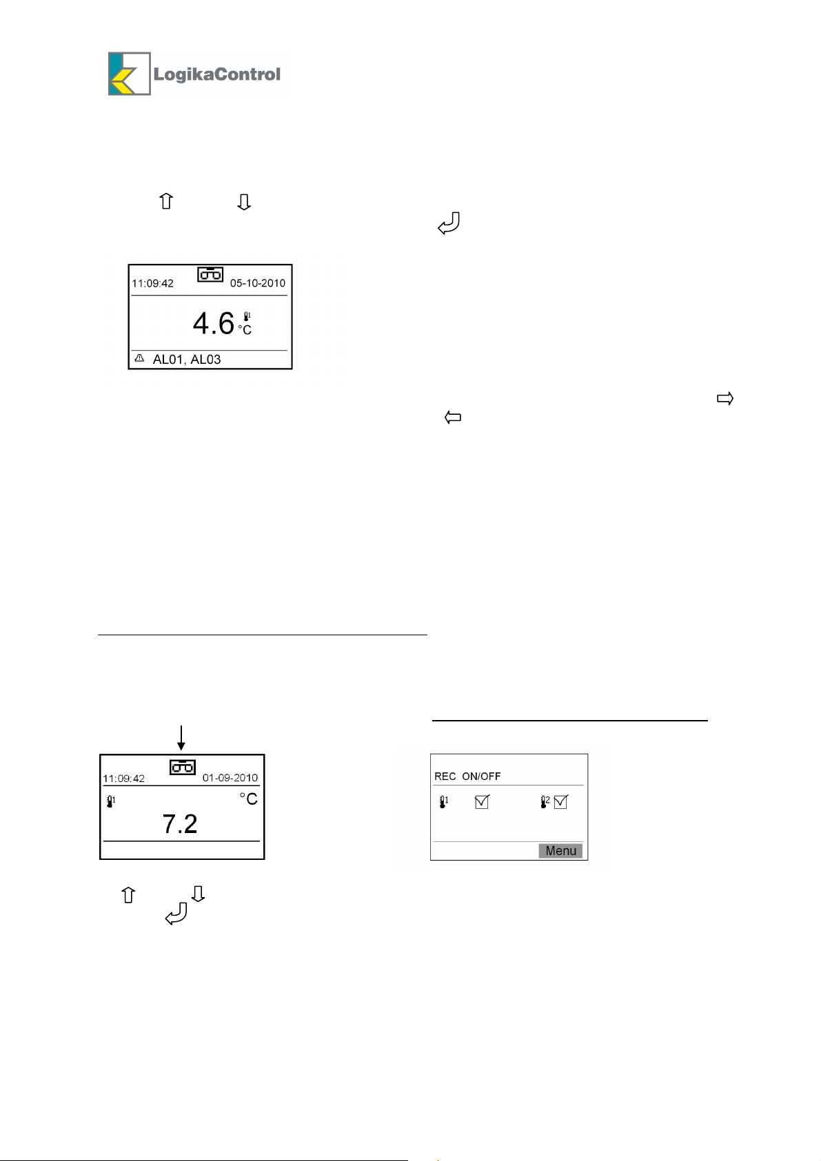
Picture nr.1: visualization with one temperature probe selected
On upper corners of the LCD are visualized the time (left) and the date (right)
Pushing (Menu) you enter into the programming device and visualization of the different
functions: flow up/down the functions through and ; once the function is selected,
confirm by .
After 3 minutes inactivity on the key buttons the visualization shift back to the
main menu automatically.
Programming functions
1. Visualizations
2. Setting
3. Records
4. Reset
5. Info
6. Communication
Rev.1 dated 16-06-2014

7
10:23 Thu 12/07/2007
°C
Visualizations 1-1
Visualizations 1-1
Italian
DST/Standard time = YES
By the buttoons and/or select the function to set and it will be visualized as reverse
(from positive to negative):
= language: Italian, English, French, German, Spanish, Greek, Portuguese –
default English
= temperature scale: °C / °F – default °C
= display contrast according ambient light where the recorder is installed
= time and date setting with possibility to switch between DLS and Standard time
where:
YES: the recorder updates the time automatically
NO: the updating DLS/Standard time is not operated
Once the function is selected by pushing the setting is enabled and the function starts
blinking: by the buttons and/or set the new data and confirm by (the function
stops blinking); after last setting the visualization shift back to the previous one.
Setting 1- 2
By the buttons and/or select the function to set and confirm by : the square on the
right starts blinking; till by and/or set the new value and confirm by ; push ESC
to shift back to the main visualization.
P01 – Company title: in the square on the right, name reported on the printing data); max.
15 alphanumerical characters; setting comes through and/or for each letter or number
(keep on pushing for fast-forward) and confirm by (the square moves on the right); at
the end of setting pushing twice (two white spaces enter) to confirm the name and quit;
in case of wrong typing, pushing ESC the cursor shift back to the previous character; keep
on pushing for about 2 seconds to cancel all the characters on the right and confirm the
last one entered.
P02 – ID Recorder (for example: cell name): in the square in the right set the code/name
will identify the recorder (name reported in the printing data); max. 15 alphanumerical
characters and the setting procedure is the same for company title as well.
P03 – Record interval (time to pass between a recording and next one): in the square on
the right is possible to change the default value (30 minutes): setting range 1 ÷ 240
minutes.
NOTE: the parameters P1-P2-P3 is required to be configured otherwise the records
can’t be downloaded to the PC through the software application.
P04 – Enabling the probes connected: in the square n the right is possible to change the
default value: T means temperature probe
1= probe T1 – default
2= T1+T2 – visualization of the parameter P07 and P08
P05 – High temperature alarm related to the probe T1: in the square on the right is
possible to change the default value 300 °C (alarm disabled): setting range 0 ÷ +300 °C.
P06 –Low temperature alarm related to the probe T1: in the square in the right is possible
to change the default value 0 °C (alarm disabled): setting range 0 ÷ +300 °C.
Rev.1 dated 16-06-2014
8
P07 – High temperature alarm related to the probe T2: in the square on the right is
possible to change the default value 300 °C (alarm disabled): setting range 0 ÷ 300 °C.
P08 – Low temperature alarm related to the probe T2: in the square in the right is possible
to change the default value 0 °C (alarm disabled): setting range 0 ÷ +300 °C.
NOTE: when temperature rise up or goes down the setting value, the timer related to
parameter P09 starts; once it’s over if the temperature is still over (up or down) the setting
value, the LCD visualizes the related alarm code and the alarm relay de-excites.
P09 – Alarm (positive/negative) delay: in the square on the right is possible to change the
default value 30 minutes: setting range 1 ÷ 60 minutes.
P10 – “Door open” alarm delay: once this time is over if the door input is still open, the
LCD visualizes the code alarm and the alarm relay de-excites; in the square on the right is
possible to change the default value 0 minutes (alarm disabled): setting range 0 ÷ 60
minutes.
NOTE:
1) If you need to set one or more parameter P05 ÷ P08, they have to be enabled once the
refrigerator reaches the working temperature only.
2) If you enter into the setting, try to change any parameter but the memory keep data not
downloaded yet, the LCD visualizes the message “DONWLOAD MEMORY”: in this case, stop
the recording and change the setting value once you’ve downloaded the memory only.
Records 1- 3
Visualization and/or print of the records stored into the memory for a defined period.
From: day – month – year
To: day – month – year
By the buttons and/or set the start/end date: every date must be confirmed by ;
after last data the LCD visualizes the followings:
1 – Visualization (see example of visualization)
2 – Download (it’s shown when the USB key is IN only)
By the buttons and/or select the function needed and confirm by .
If “Visualization” has been selected, the LCD visualizes all the records, eventual alarms
detected and the changes of any parameters (if any) with related date; flow up/down by
and/or ; by shift back to the main visualization.
If “Download” has been selected, push the related data for starting download data.
Example of “Visualizations”
The first page reports the date of the event on the upper left corner and the data of the
event in the next one.
1) example of visualization of the records with three analogue channels enabled
12/11/10 T1[°C] T2[°C]
12:15 14.5 3.5
2) visualization of the events
12:00 START REC T1-T2 (start recording)
12:00 STOP REC T1-T2 (stop recording)
12:45 AL05: Probe T1 failure (alarm activation time with related code and sliding
description for limited space)
13:08 P05 150°C (modification time of a parameter with new value)
13:18
17:52 12/11/10 (change of date and time)
Rev.1 dated 16-06-2014

9
Reset 1-4
This function allows to enable the following reset (protected by password max. 4 numbers –
default 0000):
Confirm the function by and the LCD visualizes:
Enter Password
by the buttons and/or enter the first number and confirm by to shift to the next
one (the number just entered is changed into the symbol *); after the fourth numer and
the password is right the LCD visualizes the following messages:
Setting – Records – Change Password
In case of wrong typing by pushing simultaneously it’s possible to shift back to the
previous number; if the password is wrong the LCD visualizes for few seconds the blinking
message “Password Wrong” and shift back the visualize “RESET”.
1 – Setting = the recorder returns to factory setting, before the installation; this function is
allowed if there is not any data into the memory only; in case of data into the memory the
LCD visualizes the message “DONWLOAD MEMORY”.
2 – Records = erase the records memory; this function is allowed if there is not any data
into the memory and no recording in progress only; in case of data into the memory the
LCD visualizes the message “DONWLOAD MEMORY”.
Select the function needed and confirm by : the LCD visualizes the message:
“Are you sure ?” and “NO”(visualized as reverse) / “YES”
If “YES” is confirmed by the blinking message “Resetting” is visualized to indicate reset
in progress; once reset is finished the LCD shift back to the previous visualization.
If “NO” is confirmed by the LCD shift back to the previous visualization.
3 – Change password
Confirming by the password setting is shown again: enter the new password according
the same procedure and the new password will be typed once requested into the Reset
function.
NOTE: it’s advisable to change the default password number in case the device is used by
personnel not authorized to this function.
PASSWORD MISSED?
In case of password missed/forgotten, take power off; supply power again keeping the
buttons and simultaneously pushed for 5 seconds while the LCD visualizes the blinking
message “D.P.L.” (loading default password).
To enter into the Reset menu now you have to enter the default password “0000”.
----
Rev.1 dated 16-06-2014
10
PIN
Info 1-5
Into this function you can read:
- firmware version
- company title and ID recorder (setting data)
- buffer memory status (%)
Communication 1-6
By the buttons and/or select the desired function and confirm by .
Communication allows to visualize/change the following parameters:
P20 - Mode: MODBUS default) or GSM
a) When MODBUS is selected, the parameter P21 is visualized only
b) If GSM is selected (the display visualizes “GSM = 00000” where you have to enter
the SIM number placed into the module – just as reminder) the display visualizes the
parameters P22÷P26.
P21 - 1 ÷ 32 (default 1): Modbus address of each unit in the net.
P22 - GSM phone number = 000000000
P23 - PIN code = 0000: if pin code is not enabled, leave 0000 (see alarm)
P24 - SMS Dest. 1 = 000000000: enter the phone number of the 1st cell phone
P25 - SMS Dest. 2 = 000000000: enter the phone number of the 2nd cell phone
P26 - SMS Dest. 3 = 000000000: enter the phone number of the 3rd cell phone
NOTE:
GSM selected
a) When an alarm is detected by the recorder, the GSM will send an SMS to the cell phones
set with the following information:
Company title – Recorder ID – probes selected – Alarm codes detected.
In case of power off and recorder powered by buffer battery, the GSM will send the
information above further to the message “ON BATTERY”; once the main power is restored
the GSM will send another SMS with the message “POWER OK”.
b) By sending from an SMS with word “STATUS” (it doesn’t matter capital letter or note)
from any cell phone to the GSM module, the GSM will reply automatically with the message
“NO ALARMS”, in case of no alarm detected or related codes in case of alarm detection.
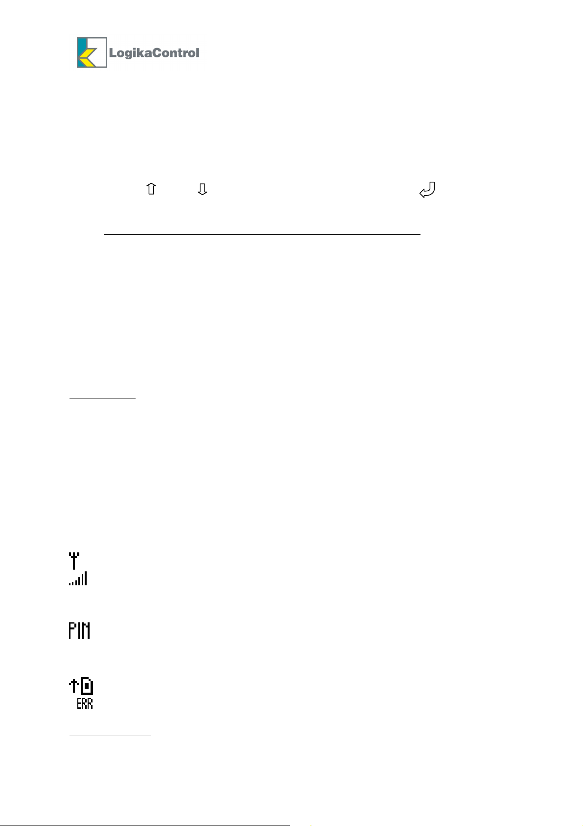
Symbols reported on the right low corner of the display of HTR connected to a GSM module:
Antenna: the GSM is connected.
Net coverage: if this symbol is blinking, it means there is not net coverage so the
GSM module has to be placed in another position.
Max. distance between HTR and GSM module no longer than 3 meters.
It blinks in case you enter a wrong pin code: in this case quit the programming,
switch off and then switch on the HTR, enter the pin code again to avoid after 3rd
wrong attempt the SIM card lock and you have to enter the puk code to unlock.
General error: replace the GSM module.
Modbus selected
in this case it is possible both monitor the temperature and download data recorded by the
several HTR connected in the net.
Rev.1 dated 16-06-2014
It blinks when the SIM card is not in.
: units connected as serial net and software application installed on the PC;

11
Visualization with two temperature probes
MESSAGES AND ALARM CODES
Messages
“Download data” due to:
a) memory full (loop memory: once it’s full overwriting starts; last data erase the first one).
b) change a parameter while data to download into the memory: disable recording and
download the data before to modify any data.
“Push button download data”: when the USB key is IN.
“Download data” (with progress bar and related %: download data in progress.
“Drive USB key – Completed” (blinking): download data over.
“Drive USB key – Error” (blinking): download data not succeed; check if the USB key is
failure or full.
“Change time DLS/Standard time”: informs about change time.
Alarm codes
AL.00 = flash memory error: the LCD visualizes the message OFF; replace the recorder.
AL.01 = timekeeper failure: after download data the LCD visualizes the OFF; replace the
recorder. The printing data reports the message “timekeeper failure”.
AL.02 = Power OFF (missing power): the printing data reports the time when power off
comes; this alarm is detected if the buffer battery is connected and the recordings are in
progress only.
AL.03 = Power ON (restore power): the time when the power is restored is recorded into
the memory; the alarm is detected with recordings in progress only.
AL.04 = Door open: door input is open over the time set in the parameter P10: close the
door; the alarm is detected with recordings in progress only.
AL.05 = Temperature probe T1 failure: the printing data reports the related alarm code;
replace the probe.
AL.06 = temperature probe T2 failure: the printing data reports the related alarm code;
replace the probe.
AL.07 = high temperature alarm: temperature detected by T1 is over set P05; alarm
detected once timer P09 is over and recordings in progress only.
AL.08 = low temperature alarm: temperature detected by T1 is below set P06; alarm
detected once timer P09 is over and recordings in progress only.
AL.09 = high temperature alarm: temperature detected by T2 is over set P07; alarm
detected once timer P09 is over and recordings in progress only.
AL.10 = low temperature alarm: temperature detected by T2 is below set P08; alarm
detected once timer P09 is over and recordings in progress only.
AL.11 = Overwriting records due to memory full; download data.
Rev.1 dated 16-06-2014
12
R
ecord
s in progress
If one or more alarms are detected, the LCD visualizes the delta icon (generic alarm
symbol) and related code; the relay contact closes between the poles 1-2 of the terminal
M3.
Pushing and/or enter the alarm active list and you can flow up and down by the same
arrow buttons; it’s possible to reset the alarm by if the cause has been solved only.
Every alarm reports date and detection time.
All the alarms are reported in the printing data with related detection date ( )
and date the related casue has been solved ( )
In case of power off and buffer battery connected, the battery icon starts blinking;
in this status the download data is not allowed (automatically disabled).
ENABLING THE DEVICE TO RECORD
Once the programming is complete, the device is ready to record according the
following way:
Temperature probe T1 connected and selected:
By the button REC. you can enable and disable the recordings; when the recording is
enabled the LCD visualizes the temperature detected and the symbol for record in progress;
when the recording is disabled the LCD visualizes the OFF.
Probes T1+T2 connected and selected:
By the button REC. the LCD visualizes
By and/or select the zone you need to enable or disable (square blinking) the recording
and push to activate (election flag is shown) or deactivate it (selection flag disappear).
Push REC to confirm and the LCD visualizes the temperature of the zone enabled for the
recording with the related recording symbol or message OFF in case it’s disabled.
Rev.1 dated 16-06-2014
13
Complete
DOWNLOAD DATA
Operation allows by the main menu only
Insert USB key in the proper housing after you remove the cover cap (D).
The LCD visualizes the message
Push the button (near USB key) and LCD visualizes the message
Drive USB key
Push button
download data
Download
Drive USB key
Under the message “Drive USB key” is a bar indicating the download progress (%); at the
end of download the bar change into the message “Complete” (blinking).
Take the USB key out and remember to cover the housing with the proper cap to keep IP
protection of the device.
The file into the USB key is converted into a non changeable format by the PC to
avoid any tampering; original data are the ones into the flash memory of the
recorder.
USB FLASH DRIVE SUPPORTED
Flash drive USB supported: class 0x08 (Mass Storage Class), subclass 0x06 (SCSI
transparent command set) and protocol 0x50 (Bulk-Only Transport), formatted FAT16 o
FAT32 with sector dimensions 512 byte (windows default)
Different File system (example NTFS or different sector dimensions, example 1024byte)
CLEANING THE DEVICE
The plastic box cab be cleaned by no aggressive detergent while the front panel by a cloth
moistened with water and soap.
DISPOSAL
The HTR is composed by plastic, cables, printed circuit and electrical
components; for this reason it has not to be disposal in the
environment.
For a right disposal ask for specialized companies.
WARRANTY
HTR temperature recorders are covered by a 24-months warranty against all manufacturing
defects as from the production date printed on the label of the device identifying the year
by the first 4 characters, the week by the second 2 characters and the progressive serial
number with the last 5 characters.
Rev.1 dated 16-06-2014

14
In case you need to use the service assistance during the warranty period, the product must
be send back to the distributor you bought it paying attention it must be intact and packed
into its original package.
Customers are entitled to have defective products repaired, spare parts and labour included.
Transport expenses and risk shall be met entirely by the Customer.
Repairs carried out under warranty do not prolong or renew the warranty expiration date.
The Warranty does not cover the following cases:
- Damages resulting from tampering, impact or improper installation.
- Behaviour inconsistent with Manufacturer’s prescriptions and instructions.
- Damages caused by repairs made by unauthorized personnel.
In all above cases repair costs shall be charged fully to the Customer.
The Manufacturer cannot be held liable for any direct or indirect damages to animals, people
or things as a result of failure to observe all the instructions/information in the user manual,
especially instructions concerning installation, use and maintenance of the device.
For all matters not expressly indicated, the warranty is subject to the regulations contained
in the Italian Civil Code art. 1512.
The competent court for any controversies is acknowledged to be the “Foro Monza”.
Logika s.r.l. cannot be held liable for possible errors or inaccuracies written in this manual
as a result of printing or transcription errors.
Logika s.r.l. reserves the right to modify its products without prior notice as it deems
necessary without altering their main characteristics.
Each new release of Logika Control user manual replaces the previous ones.
EDITION LIST
Rev.0: 1st edition 02-02-2011
Rev.1: Modified electrical drawing due to mistake in the previous one 16-06-2014
Rev.1 dated 16-06-2014
 Loading...