


Model PMP-716 Handheld Pyrometer
Operator’s Manual
Rev 1.2

Logika Technologies Inc. Model PMP-716 Operator’s Manual Rev 1.2 Aug-13
Contents
1. Introduction ...................................................................................................................... 2
2. Description ........................................................................................................................ 2
2.1 Operating Principle ................................................................................................. 2
2.2 Specifications .......................................................................................................... 4
3. Location ............................................................................................................................ 5
3.1 Sensor Location ....................................................................................................... 5
3.2 Sensor Aiming ......................................................................................................... 6
3.3 One-Color Mode ..................................................................................................... 6
3.4 Two-Color Mode ..................................................................................................... 7
4. Utility Connections ............................................................................................................ 7
5. Operation .......................................................................................................................... 9
5.1 Controls .................................................................................................................. 9
5.2 Set Parameters ...................................................................................................... 11
5.3 Status Information ................................................................................................ 14
5.4 Calibration ............................................................................................................ 14
5.5 Communication ..................................................................................................... 16
6. Notes .............................................................................................................................. 17
6.1 Environmental Temperature and Humidity ............................................................ 17
6.2 Maximum, Average and Minimum Sampling ......................................................... 17
6.3 Emissivity of Materials .......................................................................................... 19
6.4 Two-Color Slope Coefficient .................................................................................. 20
7. Maintenance ................................................................................................................... 21
7.1 Regular Maintenance ............................................................................................ 21
7.2 Returns of the PMP-716 ........................................................................................ 21
8. Dimensions ..................................................................................................................... 22
Web: www.logikatech.com Phone: 905-829-5841 Fax: 905-829-8787 Email: info@logikatech.com
P a g e | 1

Logika Technologies Inc. Model PMP-716 Operator’s Manual Rev 1.2 Aug-13
1. Introduction
The Logika Technologies Two-Color Handheld Pyrometer, Model PMP-716, is primarily used in
the metallurgical industry to measure the temperature of high speed wire rod, hot rolled steel,
molten metal and slabs/billets. Pyrometers are able to “look” into a process and measure the
target temperature from a distance, thus providing an accurate reading while eliminating
problems associated with contact measurements. Dual wavelength Infrared pyrometers are
able to overcome application challenges such as targets with a small cross-section, variable
emissivity, dust, water or other interfering media between the target and the pyrometer.
Accurate temperatures can be obtained even when the target is 90% obstructed.
The PMP-716 uses a visible laser to assist in aiming and a microprocessor to set up parameters
like emissivity, slope, response time, sampling mode etc. It also has an interior ambient
temperature compensation unit, which allows the instrument to work in temperatures of
0~50°C (32~122°F).
PM-716 is operated by a 9V 6LR61 battery. It also has real time data storage capacity which
can save up to 1000 data points.
2. Description
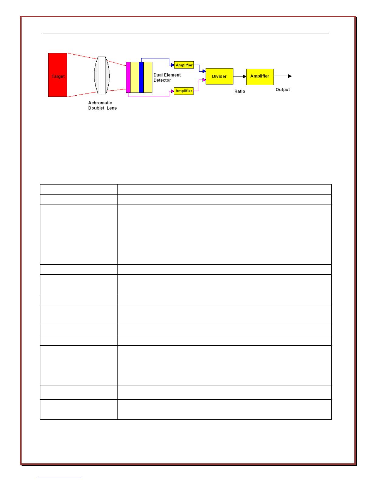
2.1 Operating Principle
This two-color (colorimetric) infrared pyrometer senses two adjacent infrared wavelengths
emitted by the target using a laminated photosensitive detector. By measuring the infrared
energy emitted from the target, the pyrometer calculates the ratio of these wavelengths to
determine the target temperature.
The primary advantage of Logika’s Two-Color Infrared Pyrometer over thermocouple
temperature measurements is that the pyrometer directly and instantaneously measures the
target temperature rather than inferring it based on the temperature of the atmosphere
surrounding the target.
The advantages of the Logika PMP716 two-color pyrometer vs. a single color pyrometer include:
• Overcomes optical fouling or interfering media between the target and the detector,
such as dust, dirt, smoke, and water vapor to yield accurate temperatures.
Web: www.logikatech.com Phone: 905-829-5841 Fax: 905-829-8787 Email: info@logikatech.com
P a g e | 2

Logika Technologies Inc. Model PMP-716 Operator’s Manual Rev 1.2 Aug-13
absolute temperature.
• Automatically compensates for changes in target emissivity or varying distance from the
target to detector.
• The target does not need to fill the detector’s field of view to accurately measure the
target temperature, allowing flexibility of pyrometer location and target position
variability. An accurate measurement may be made with as little as 10% of the
pyrometer field of view used.
Notes:
• The energy from spectral radiation
increases with higher temperature.
• These curves do not intersect. The
spectral radiation has higher energy
at all wavelengths.
• Each curve has one peak, and these
peaks move towards shorter
wavelengths as the temperature
increases. (Color shift)
• In blackbody radiation, the emitted
energy is only dependent on
In one-color pyrometer, a single reading is taken and the temperature is derived from the
radiation energy. This works under the following conditions:
• If the emissivity is known and constant
• The object fills the entire field of view
• There is no interference from smoke or dust.
Two color systems measure the ratio of two readings and calculate the temperature from the
ratio rather than the absolute value of readings. This minimizes the effects of emissivity,
optical interference and partial views of the target.
Web: www.logikatech.com Phone: 905-829-5841 Fax: 905-829-8787 Email: info@logikatech.com
P a g e | 3
Logika Technologies Inc. Model PMP-716 Operator’s Manual Rev 1.2 Aug-13
If the object remains at a stable temperature, the ratio of the radiation energy remains constant.
When the target temperature varies, the two wavelength ratio will remain the same. However,
the slope of the ratio change differs when measuring different objects (like metal and
non-metal), so a two-color slope coefficient is needed for correction.
2.2 Specifications
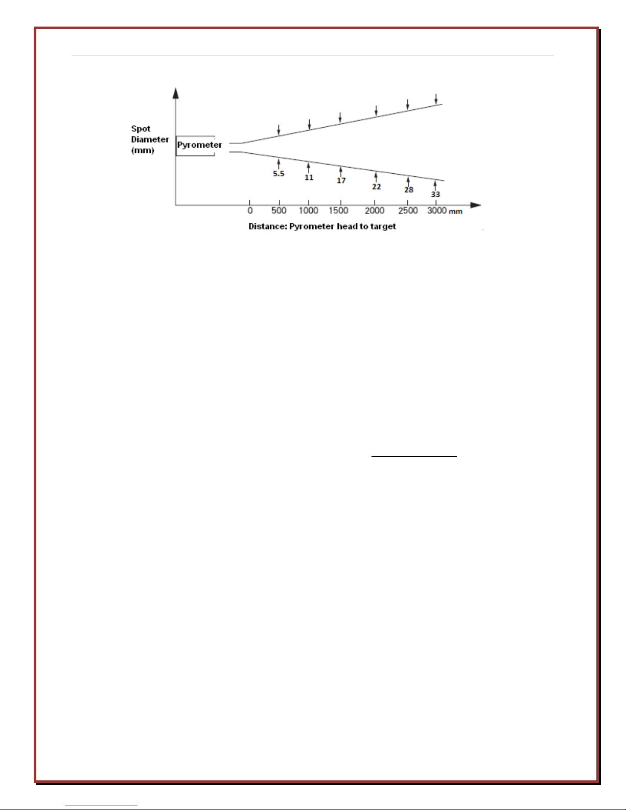
Measured range 700oC - 1600oC (1292oF - 2912oF)
Sensor Two-color laminated silicon infrared photocell
Field of View One-color mode: D/S=90:1
D is the distance between pyrometer and the target
S is the target diameter. See Figure 3.1 for more details.
Two-color mode: No restriction for field of view. The target size can
be much smaller. If temperature is greater than 900°C, the
maximum signal attenuation ratio can be 95%.
Focal Range 0.5m to ∞
Accuracy ±0.75% full scale at ambient 23°C ±5% (73°F ±9%) and humidity of
35% to 75%
Repeatability ±2°C (±3°F)
Wavelengths One-Color: 0.75 ~ 1.1µm
Two-Color: 0.75 ~ 1.1µm/1.1 µm
Response time 100 ms
Display: LCD with backlight
Modes: Real-Time: 0.1 ~ 1.0s. At 1.0s it will average over a second
Maximum (Peak): 0 ~ 999.9s
Minimum(Valley): 0 ~ 999.9s
Average: 0 ~ 60.0s
Output: RS232: 9600, N, 8, 1
Power Input: One 9V 6LR61 battery
AC/DC adaptor, DC input range 9-24V
Web: www.logikatech.com Phone: 905-829-5841 Fax: 905-829-8787 Email: info@logikatech.com
P a g e | 4

Logika Technologies Inc. Model PMP-716 Operator’s Manual Rev 1.2 Aug-13
Alarms: Adjustable high or low temperature alarm shows on display and
output via RS232
Ambient: Operation temperature 0 ~ 50°C (32 ~ 122°F)
Humidity 10 ~ 95%, no condensation
Deviation to reading at 23°C by ambient temperature:
-Two-Color Mode: ≤6°C(11°F)
-One Color Mode: ≤3 °C(5 °F)
Aiming Laser: Visible red 650 nm <3mW Class IIa
Internal Clock: Lithium battery up to 5 years life
Memory: 1000 Data points, historical data checkable
Storage temperature -20 ~ 50°C (-4 ~ 122°F)
Housing: Cast aluminum enclosure
Size: Enclosure: 230 mm L x 200 mm H x 70 mm W (9”L x 8”H x 2.75W)
Weight: 1.4 kg (3lbs)
3. Location
3.1 Sensor Location
The Logika PMP-716 Pyrometer should not be used above a heat source for extended periods of
time. Avoid direct exposure to water vapor or excessive dust or smoke
The Logika PMP-716 should be used close enough to the target to allow enough infrared energy
to reach the detector in order to provide a strong signal, but far enough from the target to
minimize the amount of heat that reaches the enclosure’s electronics.
Use Figure 3.1 to determine the PMP-716 Pyrometer’s field of view based on its distance from
the target. Only the intended target should be seen inside the field of view. Other infrared
energy sources such as rolls, other wire or billets could interfere with accurate readings.
Example: The pyrometer measures the temperature of a 5 mm steel wire with adjacent wires
5 mm on each side of the target. Use Figure 3.1 to determine that the pyrometer may be
centered on the target wire and placed up to 1500 mm away from the target wire line (15 mm
total clearance from interference from other target wire lines).
Web: www.logikatech.com Phone: 905-829-5841 Fax: 905-829-8787 Email: info@logikatech.com
P a g e | 5
Logika Technologies Inc. Model PMP-716 Operator’s Manual Rev 1.2 Aug-13
Figure 3.1: Pyrometer Distance Graph
3.2 Sensor Aiming
Use the pyrometer’s visible aiming laser to properly align the PMP-716 with the target.
Typically, the pyrometer should be centered on the target. At the same time, adjust the
detection spot by aiming laser to avoid interfering sources of infrared energy, including
reflection of hot metal or sunlight.
3.3 One-Color Mode
One-Color mode can be used to measure the average temperature in an area. The focal range of
the instrument is 0.5m ~ ∞ and the distance can be infinite as long as the measured area is large
enough. When selecting one-color mode, the object should completely cover the visual field;
usually 20% larger than the visual field.
This mode can be used for objects with level surfaces (no bending), with a viewing angle within
30° to the target’s surface. This surface should be physically and chemically stable (not in the
process of oxidation, gasifying or liquefying). The view to the object must also be free of
airborne particles and obstacles. When the background temperature is higher than the
measured temperature, One-Color mode can be used as long as the target fills the entire field of
view.
Web: www.logikatech.com Phone: 905-829-5841 Fax: 905-829-8787 Email: info@logikatech.com
P a g e | 6

Logika Technologies Inc. Model PMP-716 Operator’s Manual Rev 1.2 Aug-13
Figure3.2 One Color Mode Temperature Accuracy
3.4 Two-Color Mode
Utilized when:
• Measuring small objects
• Dust, vapor or fog in the environment
• Measuring distance changes
• Part of the object is obscured.
Two-Color temperature measuring mode measures the max temperature in an area regardless
of the size of target. Since the two sampled signals will vary at the same rate, the ratio
between the two signals will not change.
Two-Color mode permits the measurement angle to be smaller than 45°. When the background
temperature is higher than the target temperature, Two-Color mode is not recommended.
4. Utility Connections
Web: www.logikatech.com Phone: 905-829-5841 Fax: 905-829-8787 Email: info@logikatech.com
P a g e | 7

Logika Technologies Inc. Model PMP-716 Operator’s Manual Rev 1.2 Aug-13
DC Power Plug
RS-232 Plug
The unit uses a 9V non-rechargeable 6LR61 battery. Remove batteries if the unit is inactive for
an extended period of time.
It can also be operated with a 9-24VDC, >200mA power supply with polarity protection and
instantaneous over-voltage protection. When supplied from an external source, the unit
automatically disconnects the battery and runs continuously in External Power Mode.
The Communications plug allows the user to upload readings to a computer.
Battery compartment
Web: www.logikatech.com Phone: 905-829-5841 Fax: 905-829-8787 Email: info@logikatech.com
P a g e | 8
Battery Compartment

Logika Technologies Inc. Model PMP-716 Operator’s Manual Rev 1.2 Aug-13
Time HH:MM:SS
Blank=No Alarms
“Recall” is Data
1C=One Color
5. Operation
5.1 Controls
The PMP-716 Pyrometer’s Control Panel is located at the rear of the enclosure.
Battery Status:
Black means OK.
White means Replace.
Date MM/DD/YY
“Scan” is Scan Mode
Real Time Temperature
in °C/°F
2C=Two-Color
LAL=Low Alarm Limit
HAL=High Alarm Limit
“Slope 1.00” means
Slope=1.0 in Two-Color
Mode
“ε=0.99” is emissivity in
“Average=1200” is
average value of
Temperature.
MAX is Maximum,
MIN is Minimum
Button function:
- “Laser”: turns the aiming laser ON/OFF.
- “Sys”
Press once: system information
Press twice: instrument calibration setup
-“Recall”: toggles between SCAN mode (running) and DATA Mode (replay) when pressed. It is
also used as an exit when modifying numerical parameters
-“Enter”: confirms the selection while in the parameter list. If pressed while in SCAN mode, it
stores the current reading. If pressed while in RECALL, it will display the most recently saved
reading. Pressing it a second time gives the option of deleting all saved readings or returning
to SCAN mode.
Web: www.logikatech.com Phone: 905-829-5841 Fax: 905-829-8787 Email: info@logikatech.com
P a g e | 9

Logika Technologies Inc. Model PMP-716 Operator’s Manual Rev 1.2 Aug-13
-“Set”: steps through five pages of setup parameters. While on a parameter page, use the UP
and DOWN arrow keys to select a parameter, press “Enter” button to change it if it is a toggle
type parameter or “Recall” if it is a numerical parameter. Continue to click the “Set” button till
the RUN screen is again displayed. The changes will then be saved to the EEPROM.
-“▲ ” button moves the cursor up or increases the selected value
-“▼”” button moves the cursor down or decreases the selected value. In SCAN Mode, this
button will toggle between 1C (One-Color Mode) and 2C (Two-Color Mode). The instrument
will return to its default mode as selected in the parameters when power is cycled.
-“Power” button turns the pyrometer on and off .
Scan mode
Recall mode
Press “Recall”, toggle SCAN/RECALL
In “SCAN” mode, press “ENTER” can save
the data.
Data N0-N999, total saved 1000 data
After 1000 data, Save function is disabled,
all data must be erased to restore this
function.
In “SCAN” mode, press ▼ to switch 1C/2C
Press “Recall”, change to “RECALL”
mode. Now the time is still changing, it
is in RECALL idle mode. Press ”ENTER”
and change to RECALL run mode.
Press “▲ ” and “▼”” to look up the
number of saved data.
Web: www.logikatech.com Phone: 905-829-5841 Fax: 905-829-8787 Email: info@logikatech.com
P a g e | 10

Logika Technologies Inc. Model PMP-716 Operator’s Manual Rev 1.2 Aug-13
Recall mode changes to SCAN mode
In Recall mode press “ENTER”
Press “▲ ” and “▼”” to adjust
the cursor location, either select
delete all the data or EXIT
Press “ENTER” to exit
5.2 Set Parameters
Press “Set” button, enter parameters setup menu.
Press “▲ ” and “▼”” to adjust the cursor location
Press “ENTER” to select the parameter, and use “▲ ” and “▼”” to adjust the setup value
Press” RECALL” to EXIT
Parameter 1 - One-Color/Two-Color Operation: Toggles between 1 Color and 2 Color
measurement. Also changes by pressing “▼””
Parameter 2 - Emissivity: Only applies to One-Color Operation. See chart for typical
emissivity settings. Emissivity coefficient ↑0.01, Reading ↓1°C.
Parameter 3- Slope Coefficient: Only applies to Two Color Operation. Range from
0.800-1.200, increments 0.001. Slope ↑ 0.001, Reading↓ 1.2 °C.
Parameter 4 - Display: Toggles between Celsius and Fahrenheit.
Parameter 5 - Sample Mode: Choose between Max, Average and Min.
Parameter 6 - Sample Time: Max temperature: set the time 0.1~999.9s
Min temperature: set the time 0.1~999.9s
Average value temperature: set the time 0.1~60.0s,
The response time for average value is the time which the signal rises to 95%. Default is =1.0s.
Web: www.logikatech.com Phone: 905-829-5841 Fax: 905-829-8787 Email: info@logikatech.com
P a g e | 11

Logika Technologies Inc. Model PMP-716 Operator’s Manual Rev 1.2 Aug-13
Parameter 7 - Real Time Display Interval: The internal sample time is 0.1s. The setup range
for the real time display is from 0.1 to 1.0s. If set to 1.0s, the displayed value is the average
over the last ten readings (0.1s each).
Parameter 8 - Power Off Time: Default power off time is 10 minutes.
Parameter 9 - Light On/Off: LCD Backlight ON/OFF. Setup takes effect after the power is
OFF/ON.
Parameter 10 - Upper Alarm: HAL (High Alarm Limit) will be seen on the LCD display if the
temperature reading is higher than the setup value. Default is 1600°C.
Parameter 11 - Lower Alarm: LAL (Low Alarm Limit) will be seen on the LCD display if
the temperature reading is lower than the setup value. Default is 700°C.
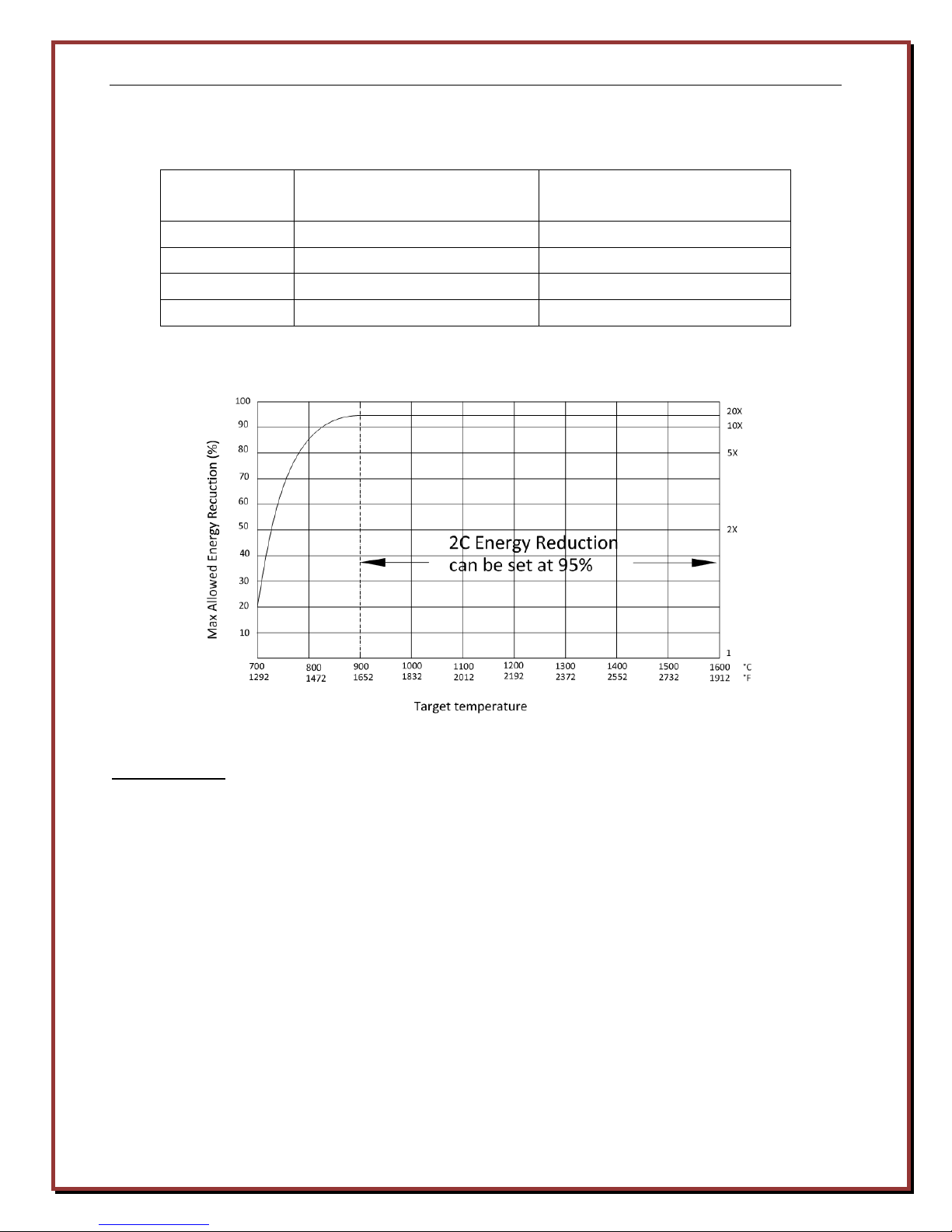
Parameter 12 - 2C Energy Reduction: Allowed signal reduction value in two-color mode.
Setting range is 0~95%. When value >95%, it shows “OFF”, and the function is off. Default
is=95%. See chart below.
2C Energy Reduction is a threshold for verifying the validation of the measured temperature.
After the target temperature is calculated by the pyrometer, it calculates each wavelength’s
emissivity at this temperature. For each wavelength, the 2C energy reduction (100% –
Emissivity value) should not be lower than the set value. If either one is higher than the set
value, the LEDs display the lower limit temperature of the pyrometer.
This function is only used in two-color mode. The setup range is 20%-100% and the default
setup value is 95%. If the attenuation ratio is set greater than 95%, this function will shut
down; and again, the lower limit temperature will be displayed. For example, if the pyrometer
is used to detect the temperature of tungsten filament of a light bar, usually the temperature is
higher than 1500°C (2732°F). The tungsten filament (target) diameter is very small at 2mm, so
the emissivity would be very low. According to Figure 5.6, if the temperature is greater than
900°C and target size is 2mm, the 2C energy reduction should be set to 95%. This means that
as long as the emissivity value for each wavelength signal is not less than 5%, the calculated
temperature is valid. In this case, the two-color mode, can still accurately calculate the
temperature. In single color mode, it would be very hard to get an accurate target
temperature in this situation.
Web: www.logikatech.com Phone: 905-829-5841 Fax: 905-829-8787 Email: info@logikatech.com
P a g e | 12
Logika Technologies Inc. Model PMP-716 Operator’s Manual Rev 1.2 Aug-13
Target size
(Diameter)
Accurate measurement with
Energy Reduction value
Simplified measurement
with Energy Reduction value
2mm-10mm 95% 95%
10mm-30mm 90% 95%
30mm-100mm 80% 95%
>100 mm 70% 70%
Parameter 13 - Real Time Clock/Calendar:
Hour = 0 ~ 23
Minute = 0 ~ 59
Year = 2002 ~ 2099
Month = 01 ~ 12
Date and Day 01 ~ 31, “Mon” ~ “Sun”
Press “Enter”, then “▼”” to “Update Time” to save new settings.
The clock is maintained by a high capacity Lithium battery:
BR2330H2A, 3V, 255mAh
Under normal working conditions, the battery should last more than five years.
Web: www.logikatech.com Phone: 905-829-5841 Fax: 905-829-8787 Email: info@logikatech.com
P a g e | 13
Logika Technologies Inc. Model PMP-716 Operator’s Manual Rev 1.2 Aug-13
Ambient Temperature: C=
˚C, F=˚F
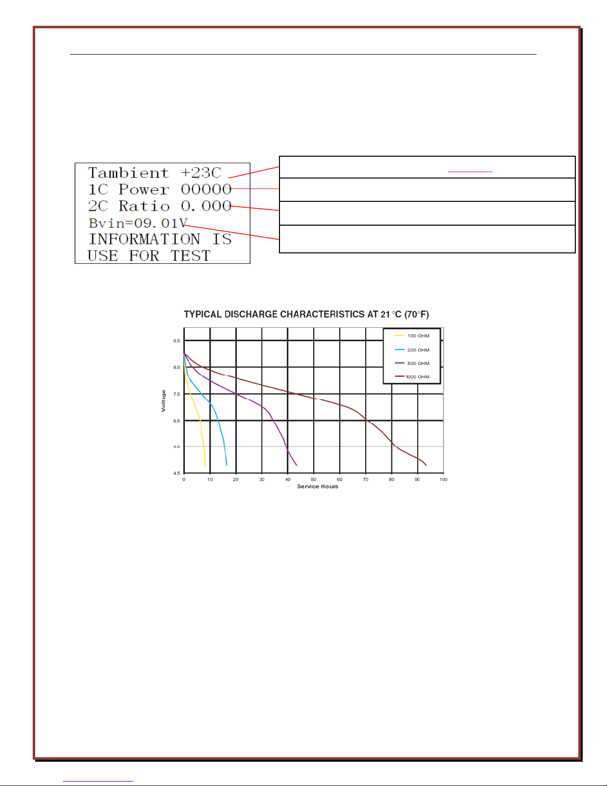
5.3 Status Information
Press “Sys” button once and it will display system information
One-Color signal energy from 16-bit A/D
Two-Color Signal Ratio
Battery voltage
9V Battery life and replacement
Battery life is determined by the status of the pyrometer. If the laser and backlight is on, the
pyrometer can work continuously for about 10 hours. When the power is OFF, the current
leakage is 1uA. When the battery voltage is low, the battery symbol changes to empty. In this
situation, all the parameters in EEPROM are locked and can’t be set until the battery is replaced.
5.4 Calibration
The instrument arrives calibrated to a “Black Body Standard” that is traceable to NIST (National
Institute of Standards and Technology). The user may re-calibrate it to own in-house standards.
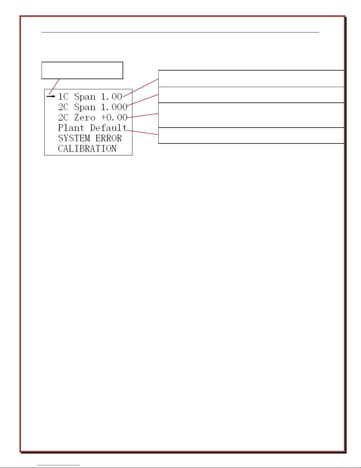
Press “Sys” twice, it will display next calibration menu
Press “Recall” to exit.
Web: www.logikatech.com Phone: 905-829-5841 Fax: 905-829-8787 Email: info@logikatech.com
P a g e | 14
Logika Technologies Inc. Model PMP-716 Operator’s Manual Rev 1.2 Aug-13
Location Cursor
One-Color Span Coefficient. Range 0.20 to 2.0. Default=0.30
Two-Color Span Coefficient. Range 0.500 to 1.300
Two-color zero-point compensation coefficient, setting range
-1.00 ~ +1.00 and default is < ±0.10.
Restores all three above to their factory defaults.
Manufacturer Test environment and conditions
Ambient temperature 23±5°C (41±9°F)
Relative humidity 35 ~ 75%
Atmospheric pressure 86kPa ~ 106kPa (12.5 PSI ~ 15.4 PSI)
Blackbody
Temperature range 500°C ~ 1600°C (932 ~ 2912°F)
Emissivity coefficient ≥0.995
Diameter 50mm
Measurements taken at 1m distance from the blackbody
The instrument should be recalibrated annually. During calibration, the surface temperature
of the blackbody is required to be stable and the blackbody oven tested by a Type B platinum
rhodium 30 / platinum rhodium 6 thermocouple or other standard thermocouple. Set the
one-color emissivity coefficient at 0.99-1.00, two-color slope at 1.000 as follows:
• One-Color span coefficient
Setting range 0.20~2.00, default =1.00, adjustment step 0.01, if coefficient ↑0.01,
temperature displayed ↓1°C. Calibration is done at above 2/3 of the instrument
measurement range, like 1200°C(2192°F). Adjust the blackbody to 1200°C, set PM716 to
one-color mode and compare the actual temperature of the blackbody with the displayed
temperature, adjust one-color span coefficient and make them equivalent.
• Two-Color Span Coefficient
Setting range 0.500 ~ 1.300, default =1.000, adjustment increments 0.001, if coefficient ↑0.001,
Web: www.logikatech.com Phone: 905-829-5841 Fax: 905-829-8787 Email: info@logikatech.com
P a g e | 15

Logika Technologies Inc. Model PMP-716 Operator’s Manual Rev 1.2 Aug-13
temperature displayed ↓1.4°C (2°F). Calibration is done at more than 2/3 of the instrument
measurement range, like 1400°C(2552°F). Adjust the blackbody to 1400°C, set PM716 to
two-color mode and compare the temperature of the blackbody with the displayed
temperature. Adjust two-color span coefficient and make them equivalent.
• Two-Color Zero-Point Compensation Coefficient
Setting range is -1.00 ~ +1.00, default <±0.10. Set the Two-Color span coefficient first.
Two-Color zero-point compensation coefficient is applicable for the instrument’s lower limit
temperature measuring section, such as 710°C (1310°F). Set the instrument to Two-Color mode
and compare the temperature of the blackbody with the displayed temperature value. Adjust
Two-Color zero-point compensation coefficient and make them equivalent.
5.5 Communication
Digital output: Format: ASCII, RS232, 9600 baud, 8 data bits, one stop bit and no parity check.
Data Transmitting Format
11:25:55 Space 07/10/12 Space
R1200C Space
Real-time
HH:MM:SS
MM/DD/YY
temperature,
Use C for“°C”,
Use F for“°F”
No.1 ~ 8 No.9 No.10 ~ 17 No.18
No.19 ~ 24 No.25
Space AVG1200 Space S1.00 Space
Average value 1200°C,
“S1.00” Two-Color
the unit is the same as
slope coefficient,
real-time temp.
“AVG” Average value,
“E0.95” One-Color
emissivity coefficient
“MAX” Max value,
“MIN” Min value.
No.2
No.30 ~ 36 No.37
No.38 ~ 42 No.43
9
2C
“2C”= Two-Color
mode, “1C”=
One-Color mode
No.26 ~ 28
NAL
“NAL” =No alarm
“HAL”=Hi alarm
“LAL”=Lo alarm
No.44 ~ 46
Web: www.logikatech.com Phone: 905-829-5841 Fax: 905-829-8787 Email: info@logikatech.com
P a g e | 16
Logika Technologies Inc. Model PMP-716 Operator’s Manual Rev 1.2 Aug-13
Space
Name of internal instrument
No.47
PMP-716 Space
Serial number of instrument
No.48 ~ 54 No.55
6. Notes
6.1 Environmental Temperature and Humidity
Operating ambient temperature 0 ~ 50°C (32 ~ 122°F)
Humidity 10 ~ 95%, no condensation
Built in temperature compensation 0~50°C (32 ~ 122°F)
Deviation for readings at 23°C:
• One-color mode <3° C (5°F)
• Two-color mode <6°C (11°F)
SN1000 CR LF
No.56 ~ 61 No.62 No.63
6.2 Maximum, Average and Minimum Sampling
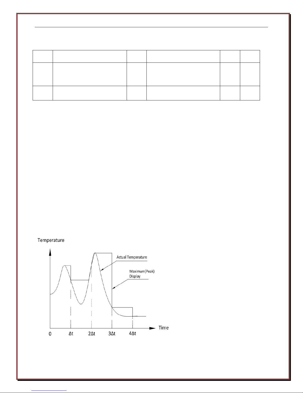
Maximum (Peak) Value Temperature Measuring Method
The holding time of a Maximum value can
be set through the buttons on the back of
the unit. The instrument will hold and
display the Max value of varying real-time
value in a selected time interval Δt.
Application: For measuring moving targets
(such as steel plate or steel wire).
Examples: The steel wire is vibrating; or
liquid metals when highest temperature is
required.
Web: www.logikatech.com Phone: 905-829-5841 Fax: 905-829-8787 Email: info@logikatech.com
P a g e | 17

Logika Technologies Inc. Model PMP-716 Operator’s Manual Rev 1.2 Aug-13
lowest temperature is required.
Average value temperature measuring method
The average time duration can be set
through the controls on the back of
the unit. The instrument will calculate
and display the average value of the
varying real-time value in a selected
time interval Δt. This first-order RC
calculation can reduce the variation of
temperature.
Application: Ideal for most field
applications or if there is scale or
oxidation present.
Minimum (Valley) Value Temperature Measuring Method
The sampling period of Minimum
value can be set through the buttons
on the back of the unit. This
method functions similarly to the
Maximum Method, but holds the
minimum value instead.
Application: Measuring surface
temperature of liquid metals when
Web: www.logikatech.com Phone: 905-829-5841 Fax: 905-829-8787 Email: info@logikatech.com
P a g e | 18

Logika Technologies Inc. Model PMP-716 Operator’s Manual Rev 1.2 Aug-13
Material and Status
Temperature Scope
(℃) Emissivity(about
1μm)
Steel:
Liquid state
0.35~0.45
Cast iron:
Liquid state
0.35~0.4
Stainless steel:
Oxidized through a temperature over
800℃
0.85
Copper:
Liquid state
0.15~0.21
Uranium
0.5~0.55
Hydrargyrum
(
liquid state)
0.2~0.25
Cobalt:
Roughened
with serious oxidation
0.7~0.75
Nickel
and its plate:
Roughened
with serious oxidation
0.8~0.9
0.8~0.9
Bismuth
0.34
Silver and Silver Plate P
late:
Roughened
with slight oxidation
0.15~0.35
Tungsten
(tungsten ribbon lamp)
1500
3000
0.3~0.39
0.3~0.36
Magnesium:
Roughened
without oxidation
0.1~0.2
Roughened
with serious oxidation
6.3 Emissivity of Materials
Material Emissivity Table
Polished without oxidation
Polished with slight oxidation
Roughened without oxidation
Roughened with slight oxidation
Serious oxidation
Polished without oxidation
Polished with slight oxidation
Roughened without oxidation
Roughened with slight oxidation
Serious oxidation
Smooth surface
Smooth slight oxidation
Serious oxidation
Iridium
Polished without oxidation
Polished with slight oxidation
Polished with serious oxidation
Roughened without oxidation
Roughened with slight oxidation
100~1200
100~1200
room temperature~800
100~1000
100~1000
100~1000
0.05~0.1
0.45
0.25~0.35
0.5~0.6
0.8~0.95
0.3
0.5
0.5
0.75
0.8~0.95
0.2~0.25
0.5
0.8
0.25~0.3
0.25
0.5
0.7
0.35
0.55~0.6
Polished without oxidation
Polished with slight oxidation
Polished with serious oxidation
Roughened without oxidation
Roughened with slight oxidation
Black nickel oxide 500~1000
Roughened without oxidation
Belt roughened without oxidation
Platinum:
Polished without oxidation
Polished with slight oxidation
Polished with serious oxidation
Roughened without oxidation
Roughened with slight oxidation
Web: www.logikatech.com Phone: 905-829-5841 Fax: 905-829-8787 Email: info@logikatech.com
P a g e | 19
100~1000
100~900
2000
50~1000
0.25
0.8~0.9
0.35
0.1~0.25
0.3~0.37
0.25
0.4~0.5
0.4
0.5
0.3
0.4
0.3
0.4

Logika Technologies Inc. Model PMP-716 Operator’s Manual Rev 1.2 Aug-13
Platinum black
0.95
Tantalum:
Roughened
with serious oxidation
0.75~0.85
Palladium
0.33
Stibium
0.5~0.65
Beryllium:
Smooth oxidation
0.3~0.4
Brick
Silicon dioxide brick
1000
0.5~0.6
Alumina
Granularity
10~100 micron
1000~1500
Economet
:
Roughened
with serious oxidation
0.8~0.9
Carbon
Graphite
0~1500
0~1500
0.8~0.85
0.8
Polished without oxidation
Polished with slight oxidation
Polished with serious oxidation
Roughened without oxidation
Roughened with slight oxidation
White firebrick
Illinium
Granularity 1~2 micron
(Kermode)
Polished without oxidation
Polished with slight oxidation
Polished with serious oxidation
Roughened without oxidation
Roughened with slight oxidation
Carbon black]
100~1000
100~1000
200~1000
0~1000
0~1500
0.2
0.45
0.75~0.85
0.3
0.6
0.3
0.3~0.35
0.2~0.4
0.3
0.4
0.8~0.9
0.35~0.4
0.6
0.95
6.4 Two-Color Slope Coefficient
The slope is the ratio of the radiant energy from two adjacent wavelengths. Since the radiant
energy of both wavelengths will change in unison with emissivity, the emissivity factor is
eliminated.
The following slopes are approximations and will vary with the alloy material and surface finish:
For measuring the following oxidized surface metal materials, the slope is approximately 1.0.
Cobalt Stainless steel Nickel Iron Steel
For measuring the following metal materials with smooth, clean and non-oxidized surface, the
slope is approximately 1.03.
Cobalt Stainless Steel Nickel Rhodium Cast Iron
Tungsten Molybdenum Steel Tantalum Platinum
Web: www.logikatech.com Phone: 905-829-5841 Fax: 905-829-8787 Email: info@logikatech.com
P a g e | 20

Logika Technologies Inc. Model PMP-716 Operator’s Manual Rev 1.2 Aug-13
Unknown slope: To measure the temperature of other articles or materials, the slope can be set
according to the following steps:
• Use a trusted contact pyrometer or temperature probe to measure the temperature of
the target surface.
• Use average value mode of the pyrometer to measure the temperature on several
locations of the target.
• Adjust the slope of the pyrometer until the reading value equals the temperature of the
measured object.
7. Maintenance
7.1 Regular Maintenance
Regular attention to the following will ensure steady operation of the sensor:
Lens Cleaning- Routinely check the PMP-716 lens glass for dust or oil residue. When necessary,
clean the glass with alcohol and lens paper or soft cloth.
Calibration- Occasional calibration (see Section 5.4) will ensure that the accuracy of the
PMP-716 Pyrometer is maintained.
7.2 Returns of the PMP-716
Contact us at 1-888-856-4452 (1-888-8LOGIKA ) with the Serial Number of your pyrometer
before you return the product. If we are unable to solve the problem by phone or email, we
will then provide you with a return authorization number.
Do not return the PMP-716 without an authorization number.
If the product is out of warranty, we will provide a repair estimate and then complete the
repairs after your approval.
Web: www.logikatech.com Phone: 905-829-5841 Fax: 905-829-8787 Email: info@logikatech.com
P a g e | 21

Logika Technologies Inc. Model PMP-716 Operator’s Manual Rev 1.2 Aug-13
8. Dimensions
Web: www.logikatech.com Phone: 905-829-5841 Fax: 905-829-8787 Email: info@logikatech.com
P a g e | 22
 Loading...