

Page 1

LTH645SWE
Page 2
h
Children should be supervised to
ensure that they do not play with the
appliance
cooker
Page 3
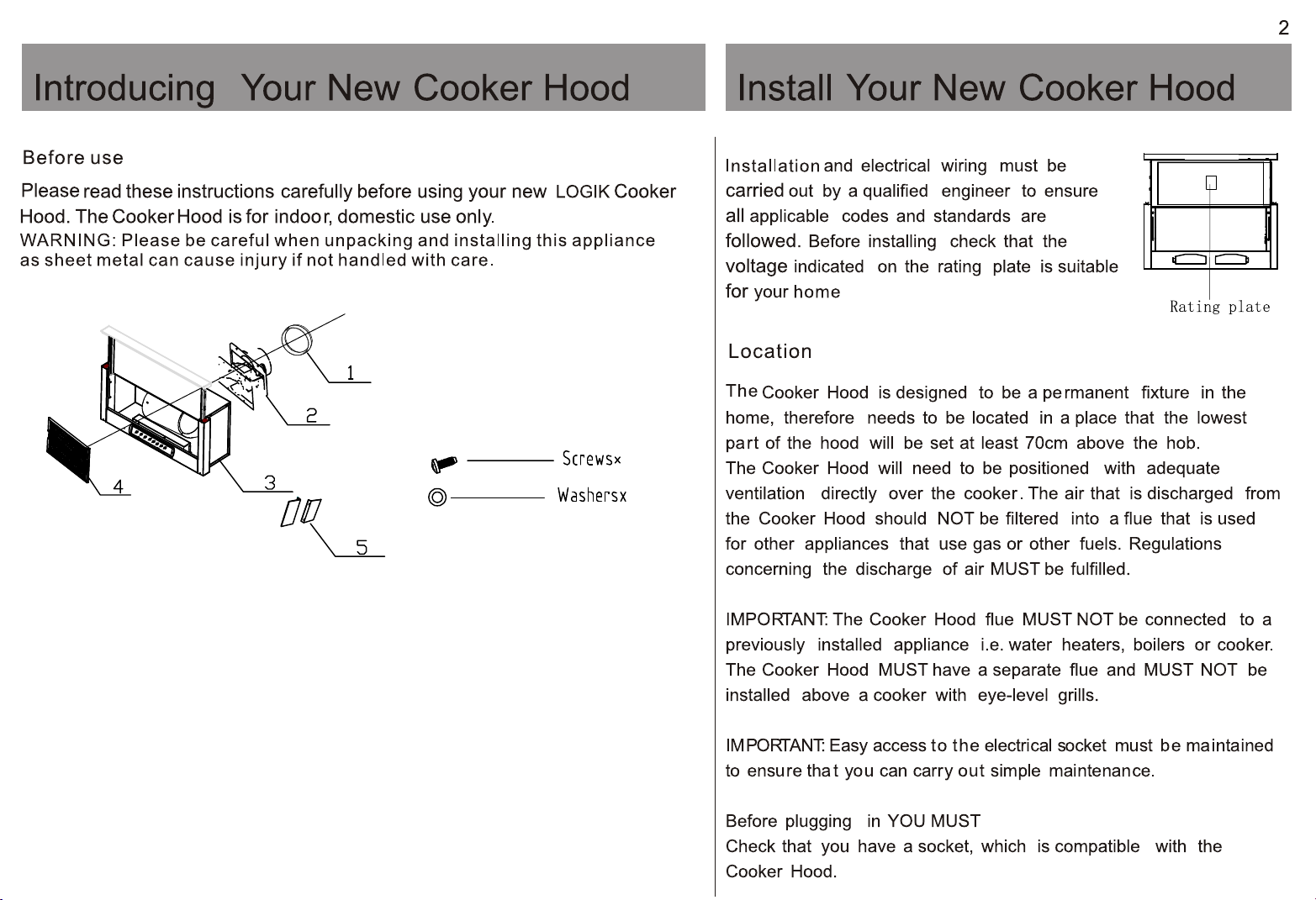
1.120mm to 125mm ducting adaptor
2.Ducting adaptor
3.Main body
14
4
4.Filter
5.Side cover
6.Screws M6*40 X4 ST4*8 X10
7.Washers x 4
Page 4

3
Installation
Before beginning any installation work ensure
the mains power has been turned off.
Ducting
1 Using a Phillips screwdriver fix the ducting
hose connector onto the air outlet of the hood.
2 Connect the hose (not supplied) to the
duct. Use the adaptor provided to
air
connect
to a 125mm hose (not supplied).
(refer to fig.1)
3 The ducting can pass through your wall
alternatively if your kitchen has a soffit,
then the ducting can be positioned to run
horizontally through an outside wall directly
to a wall cap.
NOTE: a soffit is the underside of the roof
overhang, normally wood or plasitc.
Side covers
1.Attach the side covers to hood by screw.
Stencil
Use the stencil provided to help position the
hood onto the cupboard.
NOTE: Take extreme care when drilling holes
into your wall to avoid hidden electrical wiring.
1 With the stencil positioned inside cupboard,
cut out a regular hole for ducting adaptor,
and then drill 4 holes for mounting the hood.
2 Fix the hood onto the cupboard.
3 Align the 4 screw holes with that on hood
and then use 4 screws to fix the hood in position.
0
4
*
6
M
-
4
Page 5

4
Installation
Re-Circulation using Carbon filters
Two carbon filters (not supplied) can also be
added to your Cooker Hood, when air is to
be re-circulated instead of external ducting.
Attach to either side of the motor.
Please see the Partmaster Direct details on the
back cover to order one - for UK only.
(2 carbon filters required)
Re-circulation using carbn filters
Carbon Filter
Align the rib in filter with the slot in fan guard.
Slide the filter in position.
The filter is locked.
In Use
Control panel Regular cleaning will help to maintain the
t
o
M
r
ct
L
Speed switch
0 = Switch the cooker hood off.
l = Low speed. Suitable when low levels of
steam are created whilst cooking.
ll = High speed. Suitable when high levels
of steam are created whilst cooking.
Lamp switch
l = Switch the overhead light on.
0 = Switch the overhead light off.
The mains supply will be cut if the telescopic board is not
pull out.
S pma
h
iw
o
t
S
i
hc
w
Cleaning
effectiveness of your Cooker Hood.
1 Switch off and unplug the Cooker Hood
before
2 Clean the inside and outside of the
Cooker
mild
NOTE:
damage the Cooker Hood.
may
Please be careful when cleaning this appliance as
sheet metal can cause injury if not handled with care.
cleaning.
Hood with a damp cloth and a
detergent.
Do not use solvents or abrasives as this
Press the knob to release the filter.
Take out the filter.
The Cooker Hood should be left on for at least 15
minutes after cooking has finished to ensure efficient
filtering of the air.
Page 6

5
Cleaning the filters
To ensure the filters do not become a fire
hazard we recommend they are washed ever y
3 months. Do not check the filter panels whilst
the Cooker Hood is in use.
1 Before cleaning the filters always switch
off and disconnect the electrical suppl y.
Fully extend the telescopic board.
2
Remove the filter panels by holding down
the buttons on each panel and
lifting the filter side way
They can then be taken out
hood.
3 Wash each filter in warm water and a
mild detergent, leave to soak and drain.
Ensure it is completely dr y before
replacing into the Cooker Hood.
of the
cooker
Changing the panel
This cooker hood is originally fitted with stainless
steel panel that for easier cleaning. In order to get a
good matching with your kitchen, the front panel can
be changed depending on your choice. E.g. Wood.
It is recommend that a qualified person, experienced
in fitting cooker hoods, is consulted before changing.
1. Always remember to switch off and
disconnect the electrical supply.
2. Fully extend the telescopic board, remove the filter
panels by holding down the buttons on each panel
and lifting the filter side way. They can then be
taken out of the cooker hood.
3. 6 screws holding the panel is located on the inward
side of the telescopic board. Use a Philips
screwdriver to detach those 6 screws and remove
the panel carefully.
4. Drill 6 holes (Ø3.5 x 6mm) on the back of the new
panel;
Note: Measuring unit in mm
Note: Recommend dimension of the panel is
594 (L) x 16 (W) x 50 (H)
5.Tighten the panel onto the cooker hood with 6
screws (ST 8-Ø4mm);
4 Place the bottom of each panel into either
side of the Cooker Hood and raise the
top to click into position.
NOTE: The filter panels are also dishwasher
proof. The filter panels may alter in colour
slightly after several washes, this is not a fault.
Page 7

5
Maintenance and Troubleshooting
Changing the internal light
Allow the Cooker hood to cool for at least
30 minutes after use before changing the
light bulb.
1 Before carrying out the bulb replacement
always switch off and disconnect the
electrical supply.
2 Remove the removable filters by holding
down the buttons on each panel and
lifting the filter side way. They can then be
taken out of the Cooker hood.
3 Tilt the lamp cover (glass) upward and slide
it to the right for replacing the left light bulb,
and vice versa for replacing the right light bulb.
4 Remove the old bulb by unscrewing it in
an anti-clockwise direction.
5 Replace with a new bulb (maximum 40w)
by screwing it in a clockwise direction.
Make sure that it is secure in the bulb
holder (your cooker hood is fitted with
2x 40w bulbs).
The Cooker hood is not working
• Check it is plugged in and switched on.
• Check that the fuse in the plug has
blown.
not
• Plug in another appliance, such as a
to see if the socket is working.
lamp,
Servicing
Only
an authorised, qualified technician
should
the
perform repairs and maintenance of
appliance.
Technical specifications
Model
Rated Voltage
(V)
Rated Frequency
(Hz)
Rated Power
(W)
Weigh
(kg)
Product Dimension
h/w/d 19X50X30.5
(cm)
Bulbs 2x40W max
(E14)
Weight and Dimensions are approximate. Because we continually
to improve our products we may change specifications and
strive
without prior notice.
designs
LTH645SWE
230
50
200
8.4
6 Replace the lamp cover (glass) and the filters.
Page 8

This symbol on the product or in the instructions means
your electrical and electronic equipment
that
should
be disposed at the end of its life separately from
household waste. There are separate collection
your
systems
For
your
for recycling in the EU.
more information, please contact the local authority or
retailer where you purchased the product.
6
Cod:XXXXXXXXXX
Page 9

Visit Partmaster.co.uk today for the easiest way to buy electrical spares and accessories.
With over 1 million spares and accessories available we can deliver direct to your door the very next day.
Visit www.partmaster.co.uk
or call
0870 6001 338
(UK customers only)
Calls charged at National Rate.
 Loading...