

Page 1

Safety warnings
Damage
Never use your TV if it is damaged in
any way. Always place your TV on a
flat level surface avoiding anywhere
which may be subject to strong
vibration.
Weather
It is advisable to unplug the aerial
during an electrical storm.
Moisture
Do not allow your TV to be exposed
to rain, moisture, dust. If any liquid is
spilt into your TV it can cause serious
damage. If you spill any liquid into
your TV switch it off at the mains
immediately. Contact your store.
Interference
Do not place your TV on or near
appliances which may cause
electromagnetic interference (TV or
HiFi speakers). If you do, it may
adversely affect the working of the
unit, and cause a distorted picture or
sound.
Temperature
Avoid extremes of temperature, either
hot or cold, place your TV well away
from heat sources such as radiators or
gas/electric fires.
Ventilation
The TV must be well ventilated. Do not
cover your TV or position in a small
confined space. It is recommended
that you leave a 10cm gap all around
your TV.
Batteries
Batteries are easily swallowed by
young children. Do not allow young
children to play with the remote
control unit.
Covers
Do not remove any fixed covers as
this may expose dangerous voltages.
Standby
Do not leave your TV in standby for
long periods of time e.g. overnight or
while on holiday.
ATTENTION! If a bright stationary image is left on any TV for a long enough
period of time, (longer than 4 hours continuous display), it is possible that some
screen burn may result - this leaves a shadow of the image on the screen even
after the original image has been removed.
Stationary images to watch out for are:
TV games with static scenes (background, scores, time remaining, etc)
Programme channel identifiers shown in corner of TV screen and the red
interactive logo on BBC channels via satellite
DVD on-screen logos and displays (eg the logo displayed during audio CD
playback)
Radio station identifier screen on satellite
If a still picture cannot be avoided, then reduce the brightness and contrast levels
of the picture to minimise any damage that might occur.
Page 2

Contents
Basic TV features
Connection leads supplied
TV connections
Controls
Tuning your TV
Basic TV functions
Teletext features
Using external VCR/DVD connections
External VCR/DVD AV connection
External VCR/DVD SV connection
External VCR/DVD component connection
External VCR/DVD Scart connection
Using your PIP functions
PC connections
Troubleshooting and specifications
External Specifications
page 1
page 2
page 3
page 4-5
page 6-8
page 9
page 10
page 11
page 12
page 13
page 14
page 15-16
page 17
page 18
page 19-20
Page 3
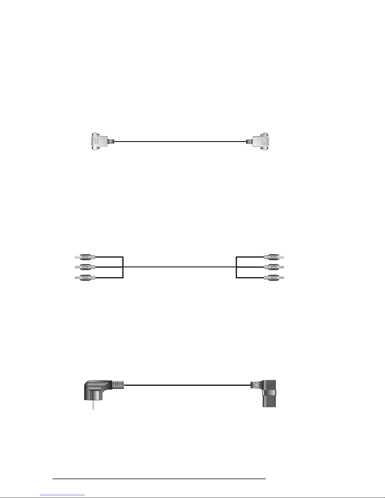
Connection Leads Supplied
1
2
3
VGA cable
AV cable
AC Power cord
1
Page 4
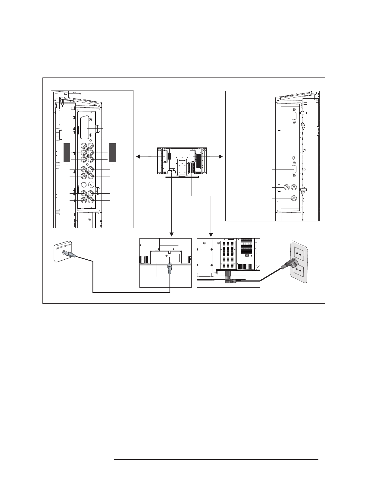
TV Connections
TV Connections
1. Connect an RF lead (not supplied) into the aerial socket and into a TV
wall socket.
2. Connect the AC power lead to the power socket on the bottom side of
the LCD TV and connect the plug into a mains socket.
Tuner
Y
Pb
Pr
R
L
S-Video
R
L
Scart
(Euro Region)
Y
Pb
Pr
R
L
Video
R
L
1 2
PC VGA(Analog)
PC Audio Input
Audio Output(L/R)
Subwoofer Output
Power
AC 220V
RF lead (not supplied)
2
RS232
Page 5
R G Y C
ON/OFF INDEX HOLD
PAGE
SIZE
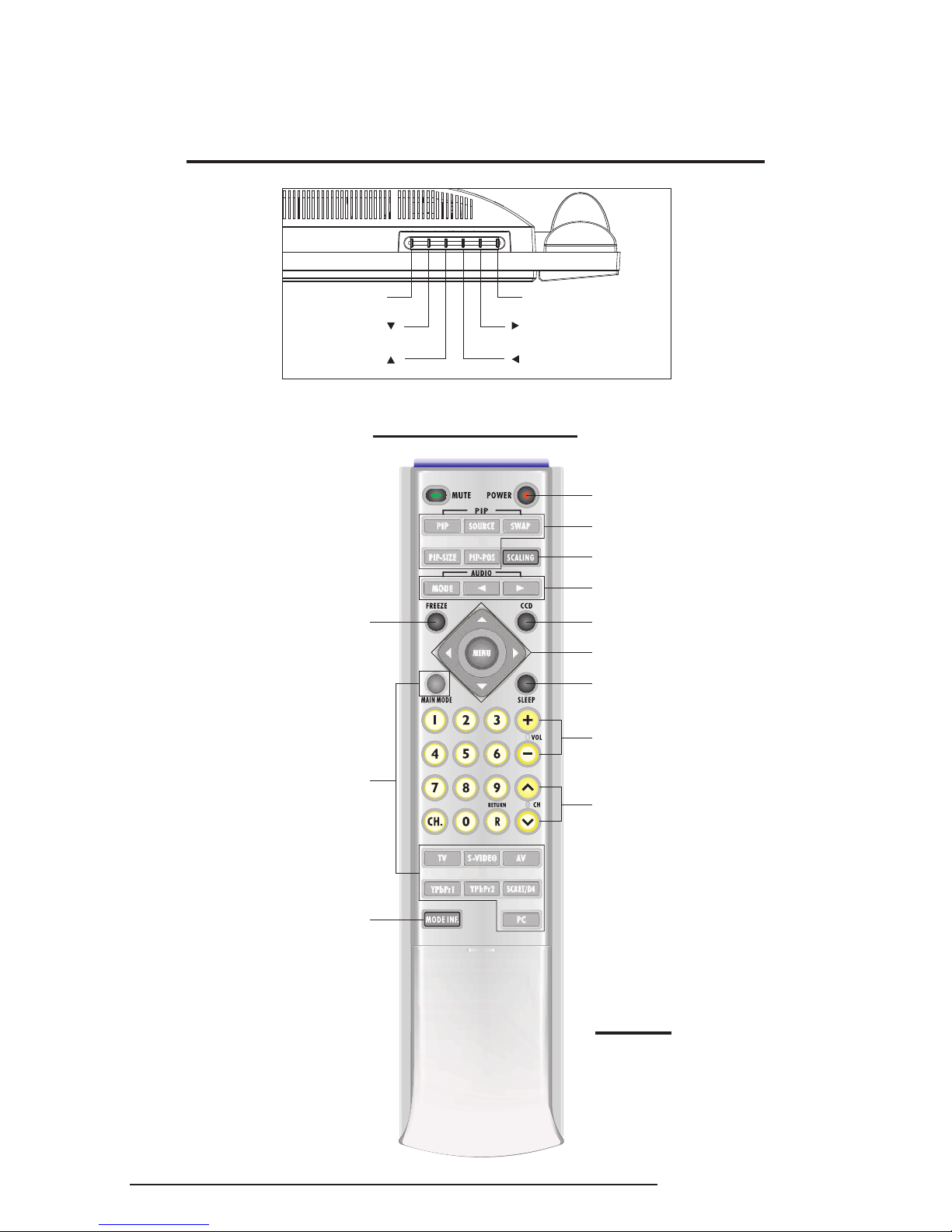
Controls
Buttons on the Right at the Top of the LCD TV
Remote Control
CH./ADJ.
VOL./ADJ.
MENU
SOURCE
Power
PIP Function Buttons
Scale of Screen Button
Sound Select
CCD
Menu Function Buttons
Sleep Control
Volume Control
Channel Control
Freeze Button
Source Select
Make sure you insert the
batteries into the remote
control before first use.
NOTE:
(for American NTSC system only)
3
Display The
Current Information
Page 6
R G Y C
ON/OFF INDEX HOLD
PAGE
SIZE
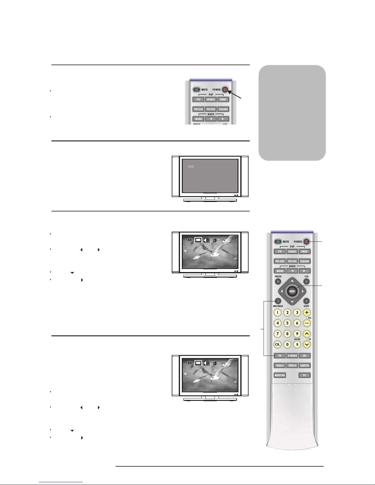
Tuning in your LCD TV
1
2
3
Switch your LCD TV ON
Select TV mode
Tune in your TV Channels
Turn power on at the mains socket to put
the LCD TV into standby mode (the standby
indicator on the front will light up in red).
If TV is not displayed on screen press the
TV button so that TV is shown on the
screen.
Press the POWER button to turn your
LCD TV on.
If you only want TV
connection, connect
your unit as shown
in the diagram and
instructions on page 2.
NOTE: We
recommend the use of
a good quality aerial
in order to receive
a strong signal.
1
(a)
2
The numbers shown next to
the buttons on the remote
control refer to the buttons
that need to be pressed in
each of the stages detailed
on this page.
1: TV
2: OFF VGA YPbPr1 YPbPr2
CHANNEL NO.: 40 MONO
4
Note: Tuning New Equipment
4
TV
CH-SCAN
TV-SYSTEM
PR-EDIT
SECAM-L
TV
CH-SCAN
TV-SYSTEM
PR-EDIT
SECAM-L
Press MENU (a) button to bring up the
OSD menu.
Press the or buttons on your
remote to select the TV icon (second from
left at the top of the TV screen).
Press to highlight "CH SCAN".
Press the button to start the tuning
process.
The screen will turn fuzzy, please be patient, the tuning process will find all
available channels. This process will take a few minutes.
Once tuning is complete the numbers in the top left of the TV screen will
disappear.
Press MENU (a) button to bring up the
OSD menu.
Press the or buttons on your
remote to select the TV icon (second from
left at the top of the TV screen).
Press to highlight "CH SCAN".
Press the button to start the update CH
tuning process.
If at any time in the future new equipment is
connected to your TV (eg a VCR, DVD player,
etc) you will need to tune it in. To do this
please follow the instructions below:
Page 7
R G Y C
ON/OFF INDEX HOLD
PAGE
SIZE
Tuning your LCD TV
The numbers shown next to
the buttons on the remote
control refer to the buttons
that need to be pressed in
each of the stages detailed
on this page.
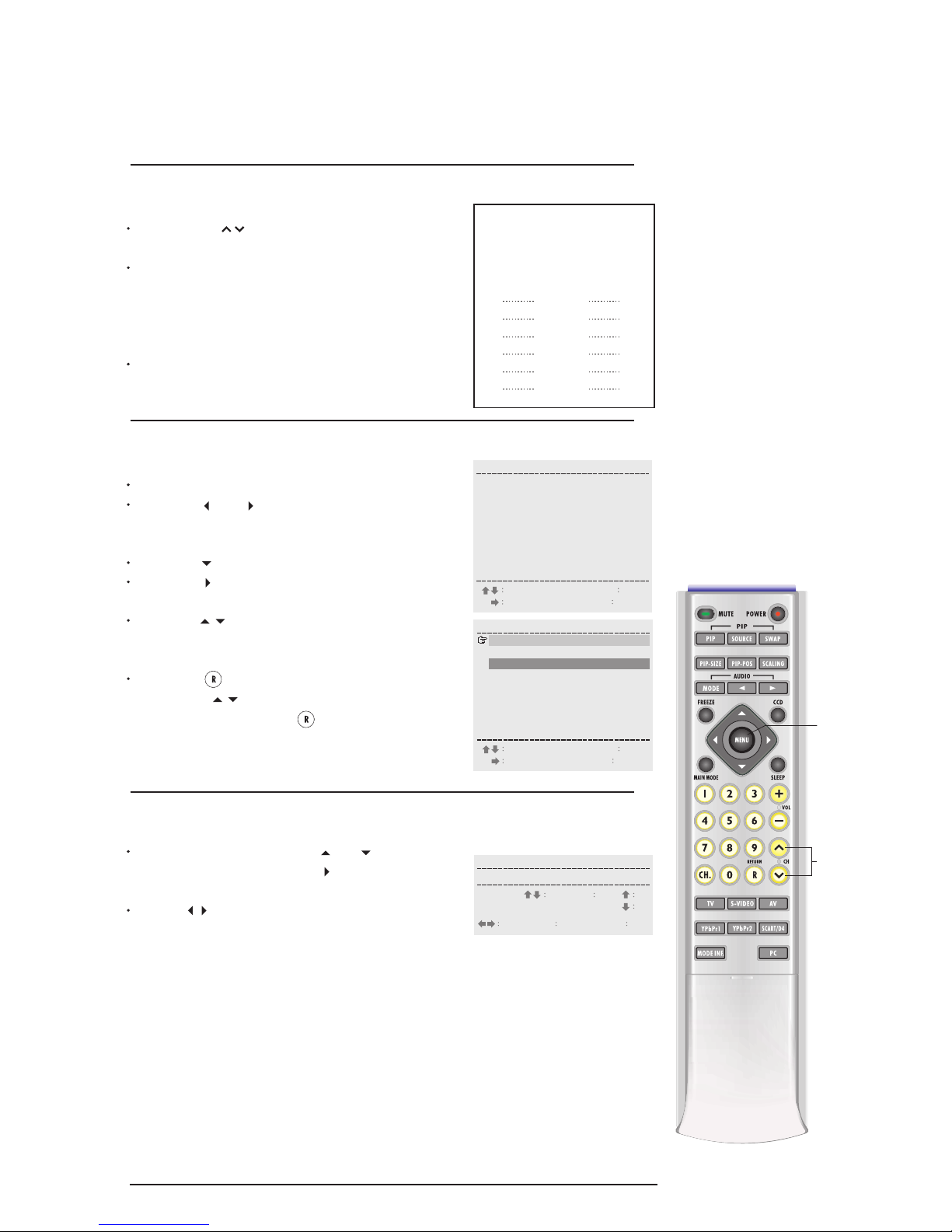
5
(a)
5
Identify channel & "PR" number
Press the CH buttons to find each
good quality picture.
Use your TV guide or Teletext to identify
the channel (eg BBC1, BBC2, ITV, etc)
and make a note of both this and the
PR number (on the top left of the TV screen)
in the chart opposite.
Repeat this process until you have a record
of the PR number for all the channels you
want to watch.
PR Channel
Name
eg PR1
eg PR4
ITV
BBC1
5
7
Naming the Channels (optional)
In the PR-EDIT screen, press or to highlight
a "PR-Number" and press the button to enter the
PR-EDIT sub menu.
Use the button on the remote control to select
the ID column. Press the number buttons to select
your required letters:
Press 1 to rotate through "A, B, C, 1".
Press 2, for "D, E, F, 2", etc.
TV-SYS (TV SYSTEM)
If you live in an area which can receive different TV
Systems you may choose to change the default
system (PAL-I) to the system used in your area eg.
PAL-BG, SECAM DK, etc.
SKIP:
"0" means SKIN ON
"X" means SKIN OFF
6
Identify "PR-EDIT"
Press MENU button to bring up the OSD menu.
Press the or buttons on your remote to
select the TV icon (second from left at the top of
the TV screen).
Press the to highlight "PR-EDIT".
Press the button and you'll see the "PR-EDIT
screen" with a list of all the "PR" numbers.
Press the buttons to highlight (in red) the
channel that you wish to move to your prefered
location (eg BBC1 to location 1).
Press the button to change the highlight to
yellow. Use buttons to select the channel
location (eg 1) and press again to switch the
two channels.
PR Freq ID SKIP
1
2
3
4
5
6
7
8
9
48
55
62
---
---
---
---
---
---
o
o
o
X
X
X
X
X
X
SELECT
ENTER
MENU EXIT
TV-SYS
PAL-DK
SECAM
PAL-DK
R MOVE
PR Freq ID SKIP
1
2
3
4
5
6
7
8
9
48
55
62
---
---
---
---
---
---
o
o
o
X
X
X
X
X
X
SELECT
ENTER
MENU EXIT
TV-SYS
PAL-DK
SECAM
PAL-DK
R MOVE
AA
BB
PR TV-SYS ID SKIP
1 --- o
SELECT
MENUE XIT
SEL 0-9 IDxo
RC LEAR
Freq
Page 8

R G Y C
ON/OFF INDEX HOLD
PAGE
SIZE
Basic TV functions
1
2
3
4
5
Changing channels
Adjusting the volume
Using the MUTE function
AUDIO settings
Using the RETURN function
Press the "CH " button to change
channels up or down.
Press the "VOL " button to turn
the volume up or down.
Press the "MUTE" button to turn off the
sound.
Press the "MUTE" button again to turn the
sound back on.
Press "MODE" button and " ", " "
button to select stereo, mono, dual 1 and
dual 2.
Press the "RETURN" button to swap to
the last channel that you were watching.
This feature is useful when you constantly
want to swap between two channels.
Alternatively, use the numbered buttons
(0-9) to go directly to a specific channel.
3
1
The numbers shown next to
the buttons on the remote
control refer to the buttons
that need to be pressed in
each of the stages detailed
on this page.
2
4
1
5
MONO STEREO SAP DUAL 1 DUAL 2
PR 48 ++++
PR 48 ++++
9
9
6
Page 9

R G Y C
ON/OFF INDEX HOLD
PAGE
SIZE
7
Adjusting picture settings
Press the "MENU" (a) button in TV mode.
Press the
" " (b) " " (c) button to select
the Main Menu to setting that you wish to
change.
Press the " " (d) " " (e) button to select
Sub Menu to setting that you wish to change.
Press the " " (b) " " (c) button to change
the setting.
Your selected setting will affect all TV channels.
Press the "MENU" (a) button again to return to
the main screen.
(d)
(e)
(b)
(c)
Basic TV functions
The numbers shown next to
the buttons on the remote
control refer to the buttons
that need to be pressed in
each of the stages detailed
on this page.
(a)
DISPLAY
CONTRAST
BRIGHTNESS
COLOR
HUE
SHARPNESS
RECALL
42
28
25
25
4
DISPLAY
CONTRAST
BRIGHTNESS
COLOR
HUE
SHARPNESS
RECALL
42
28
25
25
4
7
8
Using the CH. button
Use the CH. button to display the current
channel information on the LCD-TV screen.
PR 48 ++++
9
Using the SLEEP button
The SLEEP feature is used to automatically shut
off this LCD-TV after a preset period of time has
passed. Press the SLEEP button repeatedly to
selet 0, 30, 60, 90 or 120 minutes. Selecting 0
turns the SLEEP feature off.
COUNT DOWN: 59MIN
SLEEP TIME: 60MIN
10
Using the FREEZE button
Use this button to hold a particular image on screen. This may be useful
in making fine color adjustments.
8
10
9
6
Using the MODE INF. function
Press the "MODE INF." button to show the
setting information on the screen.
1: TV
2: OFF VGA YPbPr1 YPbPr2
CHANNEL NO.: 40 MONO
6
Page 10

R G Y C
ON/OFF INDEX HOLD
PAGE
SIZE
Basic TV Functions
11
Using the SCALING button
Use the SCALING button on the remote control
to switch the aspect ratio as indicated here:
8
FILL ALL
Use FILL ALL to stretch programs to occupy
more of the screen. Use FILL ALL to view wide
format DVD movies, or enhanced for 16:9 TV.
4:3 MODE
Use 4:3 MODE to maintain the correct original
aspect ratio for most videotape, broadcast
television, cable, satellite.
PANORAMIC
Use PANORAMIC to expand 4:3 aspect ratio
content horizontally using creative non-linear
formula. Objects in the middle maintain the
original aspect ratio and only the two sides are
expanded.
WIDE
Use WIDE to expand letterbox content to occupy
more of the screen. Use this mode to zoom
the image up to approximate to full screen.
The unused portions on the top and bottom of
the screen will appear black.
11
The numbers shown next to
the buttons on the remote
control refer to the buttons
that need to be pressed in
each of the stages detailed
on this page.
Page 11

Teletext features
1
2
3
4
5
6
Using the Teletext feature
Using the coloured buttons
Using the SIZE button
Using INDEX
Using the PAGE button
Using the HOLD button
Slide the cover downwards on the bottom
of the remote control.
Teletext is ready for use.
Press the "ON/OFF" button to access
the Teletext menu.
Press the numbered buttons (0-9) to type
in the page number of your choice.
Press the coloured button of your choice
(red, green, yellow or blue) to access the
quick menus at the bottom of the text page.
Press the "SIZE" button to change the size
of font (full screen, top half, and bottom half).
FULL(full screen) standard full-screen text
TOP(top half) top half of page appears
on the full screen
BOTTOM(bottom half) bottom half of page
appears on the full screen
Press the "INDEX" button to return to page
100 or the indexing picture; and then press
0 to 9.
Press "PAGE " button to view next page
on the teletext service.
Press "HOLD" button to stop the scrolling
of text pages. The text decoder stops receiving
data.
The numbers shown next to
the buttons on the remote
control refer to the buttons
that need to be pressed in
each of the stages detailed
on this page.
Teletext is the name
given to the magazine
services operated
by television companies.
A variety of information
is available including
News, Weather,
Financial and
Travel information.
Teletext is normally
transmitted whenever a
station is on air.
9
R G Y C
ON/OFF INDEX HOLD
PAGE
SIZE
1
2
3
4
5
6
Page 12

R G Y C
ON/OFF INDEX HOLD
PAGE
SIZE
1
2
3
4
5
VCR/DVD connection
Selecting AV connection
Selecting SV connection
Selecting Component
connection
Selecting Scart connection
Connect your VCR or DVD as shown on page 10-13.
Start to play a Video/DVD in your VCR or DVD.
If you have connected your Video/DVD player
using the AV method.
Press the "AV" (a) or "MAIN MODE" (b)
button continuously until main input.
CVBS is shown on the screen.
Your video should now be playing on-screen.
If you have connected your DVD player
using the SV method.
Press the "S-VIDEO" (c) or "MAIN MODE" (b)
button continuously until main input.
S-Video is shown on the screen.
Your DVD should now be playing on-screen.
If you have connected your DVD player
using the Component.
Press the "YPbPr1 or YPbPr2" (d) button
or "MAIN MODE" (b) button continuously
until main input.
YPbPr1 or YPbPr2 is shown on the screen.
Your DVD should now be playing on-screen.
If you have connected your DVD player
using the Scart method.
Press the "SCART/D4" (e) button or
"MAIN MODE" (b) button continuously
until main input.
Scart is shown on the screen.
Your DVD should now be playing on-screen.
(a)
Using external VCR/DVD connections
The numbers shown next to
the buttons on the remote
control refer to the buttons
that need to be pressed in
each of the stages detailed
on this page.
(b)
Connect your unit
to a VCR/DVD as
shown in the diagram
and instructions on
page 10-13.
(c)
(d)
1: CVBS
2: OFF VGA YPbPr1 YPbPr2
1: S-Video
2: OFF VGA YPbPr1 YPbPr2
1: YPbPr1
2: OFF TV AV SV Scart
1: Scart
2: OFF VGA YPbPr1 YPbPr2
(e)
10
Page 13

External VCR/DVD AV Connection
External VCR/DVD AV Connection
1. Connect the video lead on the lefthand side (viewed from the back) of your
LCD TV and to the video socket on your DVD or VCR player as shown
above.
2. Connect the audio-in cables on the lefthand side of your LCD TV and
connect the other end, red and white leads to your DVD or VCR player
as shown above.
Note: Consult your DVD/VCR manual for correct AV connections.
NOTE:
Connect your LCD TV as shown in the
TV Connections diagram on page 2
before using the VCR/DVD connections
shown below.
VIDEO or DVD
Y
Pb
Pr
R
L
S-Video
R
L
Scart
(Euro Region)
Y
Pb
Pr
R
L
Video
R
L
1 2
White Red
AV
11
Page 14

External VCR/DVD SV Connection
External VCR/DVD SV Connection
1. Connect the SV lead on the lefthand side of your LCD TV (as viewed from
the back) and to the SV socket on your DVD or VCR player as shown
above.
2. Connect the Audio in cable on the leftside of your LCD TV and connect the
other end Red and White leads on your DVD or VCR player as shown
above.
VIDEO or DVD
Y
Pb
Pr
R
L
S-Video
R
L
Scart
(Euro Region)
Y
Pb
Pr
R
L
Video
R
L
1 2
White Red
Audio In
SV
NOTE:
Connect your LCD TV as shown in the
TV Connections diagram on page 2
before using the VCR/DVD connections
shown below.
12
Page 15

External VCR/DVD Component Connection
External VCR/DVD Component Connection
1. Connect the Component lead on the leftside (YPbPr1, or YPbPr2) of your
LCD TV (viewed from the back) and connect the other end Red, Green
and Blue leads on your DVD or VCR player.
2. Connect the Audio in cable on the lefthand side of your LCD TV (viewed
from the back) and connect the other end Red and White leads on your
DVD or VCR player.
VIDEO or DVD
Y
Pb
Pr
R
L
S-Video
R
L
Scart
(Euro Region)
Y
Pb
Pr
R
L
Video
R
L
1 2
White Red
Audio In
Component
Green
Blue
Red
White
Red
Red
Blue
Green
NOTE:
Connect your LCD TV as shown in the
TV Connections diagram on page 2
before using the VCR/DVD connections
shown below.
13
Page 16

External VCR/DVD Scart Connection
External VCR/DVD Scart Connection
1. Connect the Scart lead on the leftside of your LCD TV (viewed from the
back) and to the Scart socket on your DVD or VCR player as shown
above.
VIDEO or DVD
Y
Pb
Pr
R
L
S-Video
R
L
Scart
(Euro Region)
Y
Pb
Pr
R
L
Video
R
L
1 2
Scart Cable
NOTE:
Connect your LCD TV as shown in the
TV Connections diagram on page 2
before using the VCR/DVD connections
shown below.
14
Page 17

Using your PIP Functions
1
2
3
Selecting main picture
Using Picture-In-Picture
Changing PIP source
Press the "MAIN MODE" button on the
remote control.
The main picture will be changed in the
sequence as follows:
TV/AV/S-VIDEO/SCART/YPbPr1/YPbPr2/VGA
Press the PIP button on the remote control,
A new small screen should appear in the
screen of your existing screen.
Press the "PIP-SOURCE" button continuously
to select between TV/AV/S-VIDEO/SCART/
YPbPr1/YPbPr2/VGA input for your new
picture.
NOTE:
Connect your unit
to a PC as shown
in the diagram
and instructions on
page 16.
The numbers shown next to
the buttons on the remote
control refer to the buttons
that need to be pressed in
each of the stages detailed
on this page.
Ext: Select TV to view TV input in your
new picture.
Press the "CH " button to change
the channel.
1: TV
2: OFF VGA YPbPr1 YPbPr2
CHANNEL NO.: 40 MONO
1: TV
2: OFF VGA YPbPr1 YPbPr2
1: VGA
2: OFF TV AV SV Scart
1: VGA
2: OFF TV AV SV Scart
CHANNEL NO.: 40 MONO
The sub-signal options change as the main
signal source changes.
15
R G Y C
ON/OFF INDEX HOLD
PAGE
SIZE
You will only be able to listen to sound from
the Main Mode Source, you will not be able to
get sound from the Sub picture.
3
1
OFF
TV AV
S-VIDEO
SCART
YPbPr1 YPbPr2
VGA
TV
AV
S-VIDEO
SCART
YPbPr1
YPbPr2
VGA
(For Europe
only)
(For Japan
only)
D4
(For Europe only)
(For Japan only)
D4
(CVBS)
CVBS
YPbPr2
YPbPr2
D4
D4
2
Page 18

R G Y C
ON/OFF INDEX HOLD
PAGE
SIZE
Using your PIP Functions
5
6
Select the Position of PIP
Using the Swap function
Press the PIP-POS button continuously
to select between 0-4.
Press the SWAP button to Swap between
main picture and Sub picture under PIP
mode.
0
2
4
1
3
Connect your unit
to a PC as shown
in the diagram
and instructions on
page 16.
5
The numbers shown next to
the buttons on the remote
control refer to the buttons
that need to be pressed in
each of the stages detailed
on this page.
1: VGA
2: OFF TV AV SV Scart
1: VGA
2: OFF TV AV SV Scart
1: VGA
2: OFF TV AV SV Scart
1: AV
2: OFF VGA YPbPr1 YPbPr2
4
Select the Size of PIP
Press the "PIP-SIZE" button to bring up the
OSD menu.
Press the "PIP-SIZE" button continuously to
select between 1-5, 5 screen size are
available.
1: VGA
2: OFF TV AV SV Scart
1: VGA
2: OFF TV AV SV Scart
6
4
16
Page 19

PC Connections
PC Connection
NOTE: Make sure that your PC is shut down and switched off before you
make any of the connections described and shown above.
1. Connect an RF lead (not supplied) into the aerial socket and into a TV
wall socket if you wish to view a TV picture and use your PC.
2. Connect your AC power socket on the bottom side of the LCD display
screen.
3. Plug the power cable into a mains socket.
4. Connect your Audio in cable on the righthand side of your LCD TV (as
viewed from the back) and to the sound output socket on your PC.
Consult your PC manual for socket positions.
5. Connect your VGA cable to the D-Sub port on the righthand side of your
LCD TV (as viewed from the back) to the relevant monitor socket on your PC.
6. Connect the Audio out cable (not supplied) on the righthand side (as viewed
from the back) of your LCD TV and the other end of the audio out sound
cable to the PC speaker connection.
Audio In
Audio Out (not supplied)
NOTE: To select PC input, press the PC button.
17
Tuner
PC VGA(Analog)
PC Audio Input
Audio Output(L/R)
Subwoofer Output
Power
AC 220V
RF lead (not supplied)
RS232
VGA cable
Page 20

Troubleshooting and Specifications
Symptom
Poor or no colour
No Teletext or strange characters
or letters on screen
Remote control does not work or
operates erratically
Aerial or connection cable is not
connected or is damaged.
Colour control is not adjusted.
Weak or exhausted batteries.
Aerial connection is poor or
possible station trouble.
Batteries placed in the wrong way.
Volume is set too low or your unit
is in Mute mode.
Check if equipment connected
via the Yellow, Red and White
connectors is on.
The skip indicator is set to "OFF".
Unable to hear sound
Lines are moving across the TV
picture
Cannot select a channel with the
CH button
Check al aerial connections
for broken or damaged wires.
If necessary replace with
new cables. Try using aerial
booster to improve the
quality of the signal.
Adjust the colour
Replace the batteries.
Check aerial connections for
broken wires or try another station.
Check that you have put the
batteries in the remote control the
right way around.
Press the VOL + button to turn up
the sound or press the MUTE
button to get out of Mute mode.
Switch off.
Follow the instruction in step 7B,
page 5 to change the skip
indicator to "ON".
Cause Solution
Model Features:
30" viewable SXGA media LCD TV
1280 x 1024 active native resolution
Wide 170 /170 viewing angle
Specifications:
Net Weight:
Dimensions:
22.5 kg
Width 890mm,
Height 540mm,
Depth 205mm
Because we continually strive to improve our products we may change specifications and
desigms without prior notice.
Weights and Dimensions are approximate.
18
Page 21

External Specifications
Display Panel Screen Size 643.2mm x 385.92mm (29.54" Diagonal)
Aspect Ratio 16:9
Number of Pixels 1280x768x3(R/G/B)
Pixel Pitch 0.5025mm pixel pitch.
Display Color 16.7M(R/G/B 8Bits)
Luminance 550 cd/m2 (Typ @ Center)
Contrast (CR>=10) 600: 1 (Typ)
Viewing Angel Horizontal: 170 Degrees Vertical: 170 Degrees
Response Time (Gray to gray) 16 ms (typ)
Expected Life Time 50,000 hrs. (minimum)
Manufacture CMO
Power Source Input Voltage AC100-240/2A
Input Current / Inrush Current 45A (RMS) max for 115 VAC,
80A (RMS) max for 230 VAC
Power Consumption Standby Mode & DPMS UNDER 10W
Operation Mode 150W
Signals Input / Output RGB In ( Mini-D 15PIN ) *1
Signals Input / Output Phone Jack In *1
Audio Ou t (RCA TYPE) *1
Subwoofer out *1
PIP PIP x 5 Size
Compatibility SXGA 1280x1024@ 60Hz
XGA 1024 x 768 @ 60,70,75Hz
SVGA 800 x 600@ 56,60,72,75,85Hz
VGA 640 x 480@ 60,72,75,85Hz
OTHER 720 x 400@70Hz ,640x400@70Hz
Internal Speaker 2 s et(R/L)8W+8W S imulative s urround
User Control [Power], [SOURCE], [MENU], [CH./ADJ. ].,
[CH./ADJ. ], [VOL./ADJ. ], [VOL./ADJ. ]
Model dimensions Widt h 89cm
Heigh t 54cm
Depth 20.5cm
Package Dimensions Widt h 105cm
Heigh t 64.5cm
Depth 37 cm
19
Page 22

External Specifications
Weight Net Weight 22.5 KG
Gross Weight 29.0 KG
Stand Weight 4.6 KG
Wall mount weight 17.9 KG
Environment Temperature(Operation/Storage) 32 F to 104 F(0 C to 40 C) / -4 F to 140 F
(-20 C to 60 C)
Relative Humidity (Operation/Storage) 10% to 90% (no condensation) / 10% to
90% (no condensation)
Pressure 500mmHg
Regulation Safety CUL/UL, CB
EMC BSMI, FCC Class B, CE,VCCI
Accessories Power Cord, PC Cable, User Manual
20
 Loading...