

Page 1
LOGIK
LCX27WN2
Service information
Page 2
Nexgen Mediatech Inc.
LCD TV Maintance Manual Hand book
Approved by:
Title:
Level 1 Service Manual
Doc. No.
Version Date of new version Contents (Revision)
V1.0 2003.11.13 New release (new product)
Preparation Date
2003/11/13
Model
27”
Version
V1.0
Prepared by:
Alex Chen
Page
1 OF 31
Page 1 2 3 4 5 6 7 8 9 10 11 12 13 14 15 16 17 18 19 20
Version
Date
Page 21 22 23 24 25 26 27 28 29 30 31
Version
Date
V1.0 V1.0 V1.0 V1.0 V1.0 V1.0 V1.0 V1.0 V1.0 V1.0 V1.0 V1.0 V1.0 V1.0 V1.0 V1.0 V1.0 V1.0 V1.0 V1.0
10/9 10/9 10/9 10/9 10/9 10/9 10/9 10/9 10/9 10/9 10/9 10/9 10/9 10/9 10/9 10/9 10/9 10/9 10/9 10/9
V1.0 V1.0 V1.0 V1.0 V1.0 V1.0 V1.0 V1.0 V1.0 V1.0 V1.0
10/9 10/9 10/9 10/9 10/9 10/9 10/9 10/9 10/9 10/9 10/9
Page 3

Nexgen Mediatech Inc.
NO
TITLE
Level 1 Service Manual
Table of content
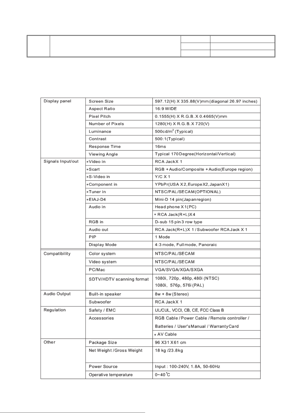
1.Electric Specifications
2.Interface
3.System Block
4.Description of Level 1 Service Tools
5.Defect mode, Possible causes and Solution for End-Users
6.Exploded view Diagram
7.Disassembly/Assembly tools and procedure
VER. A1
PAGE
2/30
8.Troubleshooting Analysis
9.Upgrade System Bios
10.Defect code, Possible Cause and Changed Parts Summary
11. Test patterns and check points
12. Remark
2
Page 4
TITLE
1 .
Electric Specifications
Nexgen Mediatech Inc.
Level 1 Service Manual
27” LCD TV Service Manual
NO
VER. A1
PAGE
3/30
3
Page 5
TITLE
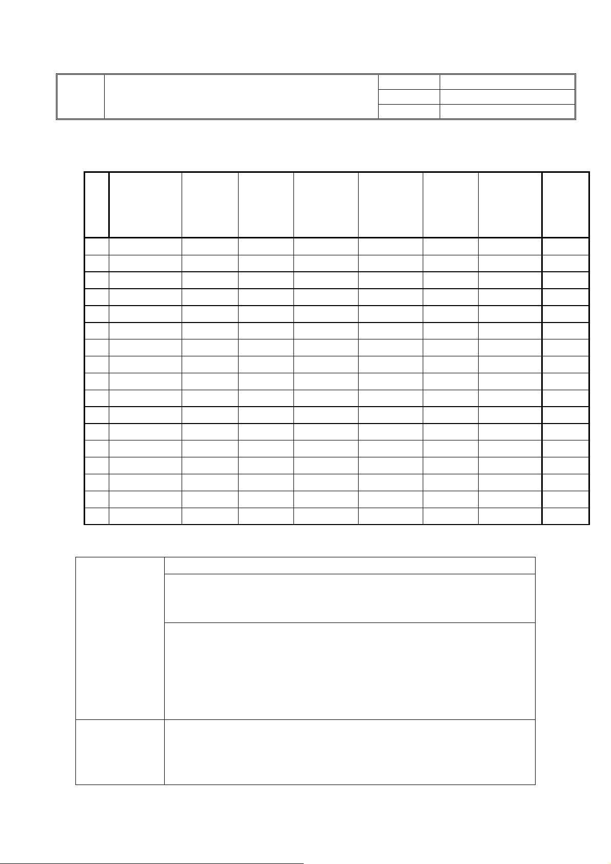
VGA Supported Timing
Level 1 Service Manual
Nexgen Mediatech Inc.
VER. A1
PAGE
NO
4/30
Standards
Item
1 NEC PC98 640x350 25.175 70.00 31.50 -/- VGA
2 MAC 13” mode 640x480 25.175 59.940 31.469 -/- VGA
3 MAC 16” mode 640x480 31.50 72.809 37.861 -/- VGA
4 MAC 17” mode 640x480 31.50 75.00 37.50 -/- VGA
5 VGA 640x480 36.00 85.008 43.269 -/- VGA
6 VGA 800x600 36.00 56.250 35.156 +/+ VGA
7 VGA 800x600 40.00 60.317 37.879 +/+ VGA
8 VESA 800x600 50.00 72.188 48.077 +/+ VGA
9 VESA 800x600 49.50 75.00 46.875 +/+ VGA
10 VESA 800x600 56.25 85.061 53.674 +/+ VGA
11 SVGA 1024x768 65.00 60.004 48.364 -/- VGA
12 VESA 1024x768 75.00 70.069 56.476 -/- VGA
13 VESA 1024x768 78.75 75.029 60.023 +/+ VGA
14 VGA 1280x1024 108.00 60.02 63.981 +/+ VGA
15 XGA 720x400 28.32 70.08 31.46 -/+ VGA
16 VESA 1280x720p 74.25 60.00 45.15 -/- VGA
17 VESA 1920x1080i 74.25 60.00 33.78 -/- VGA
Video Supported Mode
TV System
Video
Resolution
NTSC (3.58/4.43) / PAL (B/G,D/K,I) / SECAM (D/K,L)(not available for US region)
PAL:(not available for US region)
A2 and NICAM
Teletext
NTSC:
BTSC support (USA only)
EIAJ support (Japan only)
SAP/MTS
V-Chip
Close Captioning
480i SDTV support
Picture in Picture (Video on Graphic)
De-interlace support
2D noise reduction fillter
Dot Clock
(MHz)
Vertical
Scanning
Frequency
(Hz)
Horizontal
Scanning
Frequency
(KHz)
Sync
Polarity or
composite
sync (H/V)
Operating
Mode
Note
4
Page 6
TITLE
2. Interface
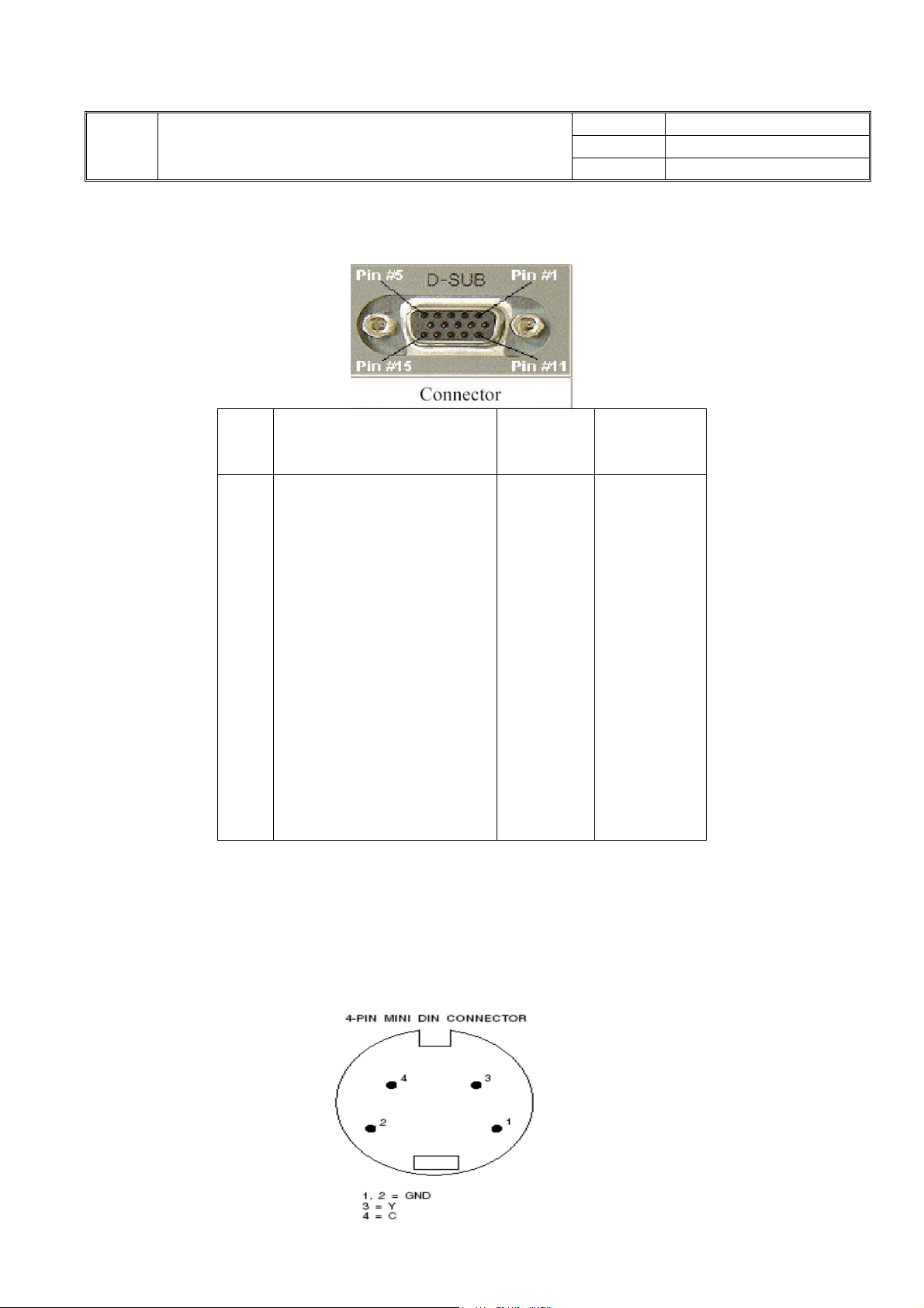
2.1 VGA Interface
Pin Function Signal
Nexgen Mediatech Inc.
Level 1 Service Manual
1
Red
2
Green
3
Blue
4
Reserved
5
Ground
6
Red Ground
7
Green Ground
8
Blue Ground
9
+5V DC
10
Sync. Ground
11
Reserved
12
DDC SDA
13
H-Sync.
14
V-Sync.
15
DDC SCL
VGA 15-Pin D-SUB Female Connector
Level
0. 7V
0.7V
0. 7V
TTL
TTL
TTL
TTL
NO
VER. A1
PAGE
5/30
Impedance
75 Ohms
75 Ohms
75 Ohms
2.2 S-Video Interface
5
Page 7
TITLE
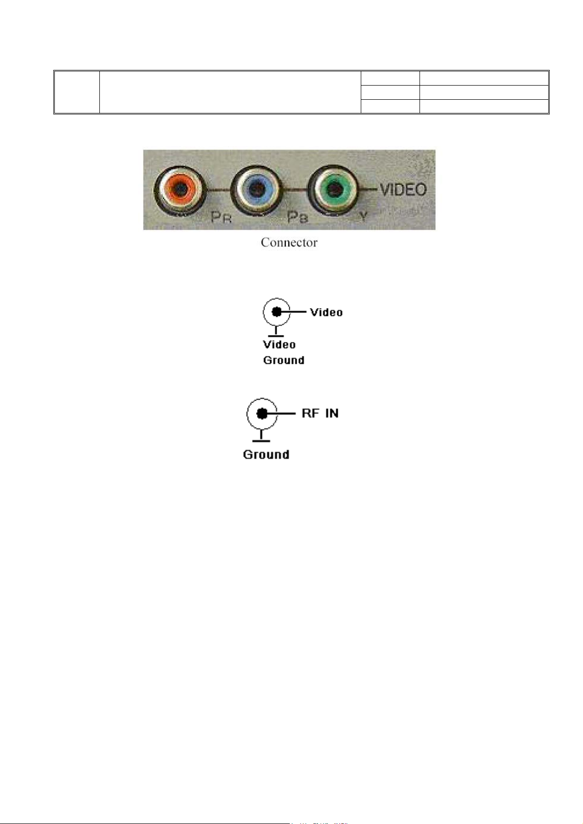
2.3 YPbPr
omposite Interface
2.4 C
Nexgen Mediatech Inc.
Level 1 Service Manual
NO
VER. A1
PAGE
6/30
2.5 TV RF Interface
6
Page 8

TITLE
3. System Block Diagram
Inverter
Level 1 Service Manual
MCU LCD Panel Interface
Nexgen Mediatech Inc.
VER. A1
PAGE
LCD Panel
NO
7/30
Audio
A/D Converter Video Decoder
OSD Keypad & Indicate LED
&Speaker Connector
LCD
Controller
Processor
&
SDRAM
DC/DC Converter TV Module
Audio & Power Interface Graphic Interface
Speaker-R
Speaker-L
Amplifier
TV
Interface
Power
Adapter
To CATV
4. Description of Level 1 Service Tools
- Multimeter
- Screwdriver Plus Type
- Test Equipment :
A : Computer for Test VGA Mode
B : DVD Player for Test AV , SV , Component (YPbPr) Mode
C : TV Pattern Generator for Test TV Mode (e.g. Fluke 54200)
7
Page 9

Nexgen Mediatech Inc.
NO
TITLE
Level 1 Service Manual
5. Defect mode, Possible causes and Solution for End-Users
Defect Mode Possible causes Solution
1.No picture
2.Abnormal colors 1.Is the signal line connected correctly? 1.Connect the signal line correctly.
3.Expanded picture
4.Picture is too dark 1.Are the brightness and contrast
5. Image too small or big 1. Need to adjust vertical control?
6.Only sound, no picture 1.Has the direction of input source
7.Only picture, no sound.
Is volume adjusted to
minimum?
8.Cannot use remote
control
9.No TV picture or picture
is unclear
10. Cannot receive
specified channels
11.No colors. 1.Is the hue/tint minimum? 1.Adjust the color setup in the Menu
12.Dotted lines or strips 1. The antenna is disturbed or is set on
13.Overlapped images or
ghost buildings)
1.Did you connect power supply core?
2.Did you turn on the power?
3.Is the signal line connected correctly?
4.Is the screen in power saving mode?
1.Is the signal line connected correctly?
2.Is the input signal outside the man-
datory frequency range?
minimum?
2. Need to adjust horizontal control?
changed?
2.Is input source connected correctly?
1.Is there any problem with input source?
2.To adjust the volume in properly.
3.Is sound line not connected?
1.Check if batteries are working?
2.Is there any disturbance from static and
thunder??
1. Cable is disconnected or connected not
very well
2. Channel is not stable
1. Never did Auto Scan
2. The channel was cancelled
3. The signal is too weak
wrong direction
2. The signal is amplified too high.
3. The signal is too weak.
1.The antenna is disturbed or is set on
wrong direction
1.Is the screen in power saving mode?
2.Turn on power supply.
3.Connect the signal line correctly.
4.Press any key of computer.
1.Connect the signal line correctly.
2.Enter signals in the mandatory
1.Adjust brightness and contrast.
1. Adjust to the wanted vertical size.
2. Adjust to the wanted Horizontal size.
1.Check the accuracy of the input source.
2.Check if circuits are connected
correctly.
1.Check the accuracy of the input source.
2.Adjust the volume to the proper level.
3.Connect sound line correctly.
1.Replace the batteries.
2.Turn off the power for 10 seconds; and
then turn it on again.
1. Connect cable line correctly
2. Fine tune the channel frequency
1. Adjust or move antenna.
2. Reduce the amplification rate.
3. Install the amplifier
1. Change input source to RF cable./
VER. A1
PAGE
frequency range.
3. Redo auto scan/Add the
channel/Fine tune the channel
frequency/Confirm the channel
exists/Confirm the antenna is
full channel(UHF/VHF)
4. Same as above
5. Same as above
Change the antenna location.
8/30
8
Page 10
TITLE
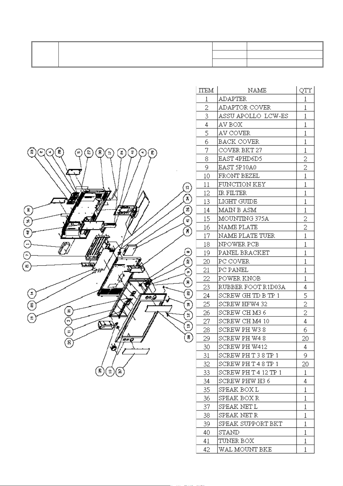
6. Exploded view Diagram
Level 1 Service Manual
Nexgen Mediatech Inc.
VER. A1
PAGE
NO
9/30
9
Page 11
Nexgen Mediatech Inc.
TITLE
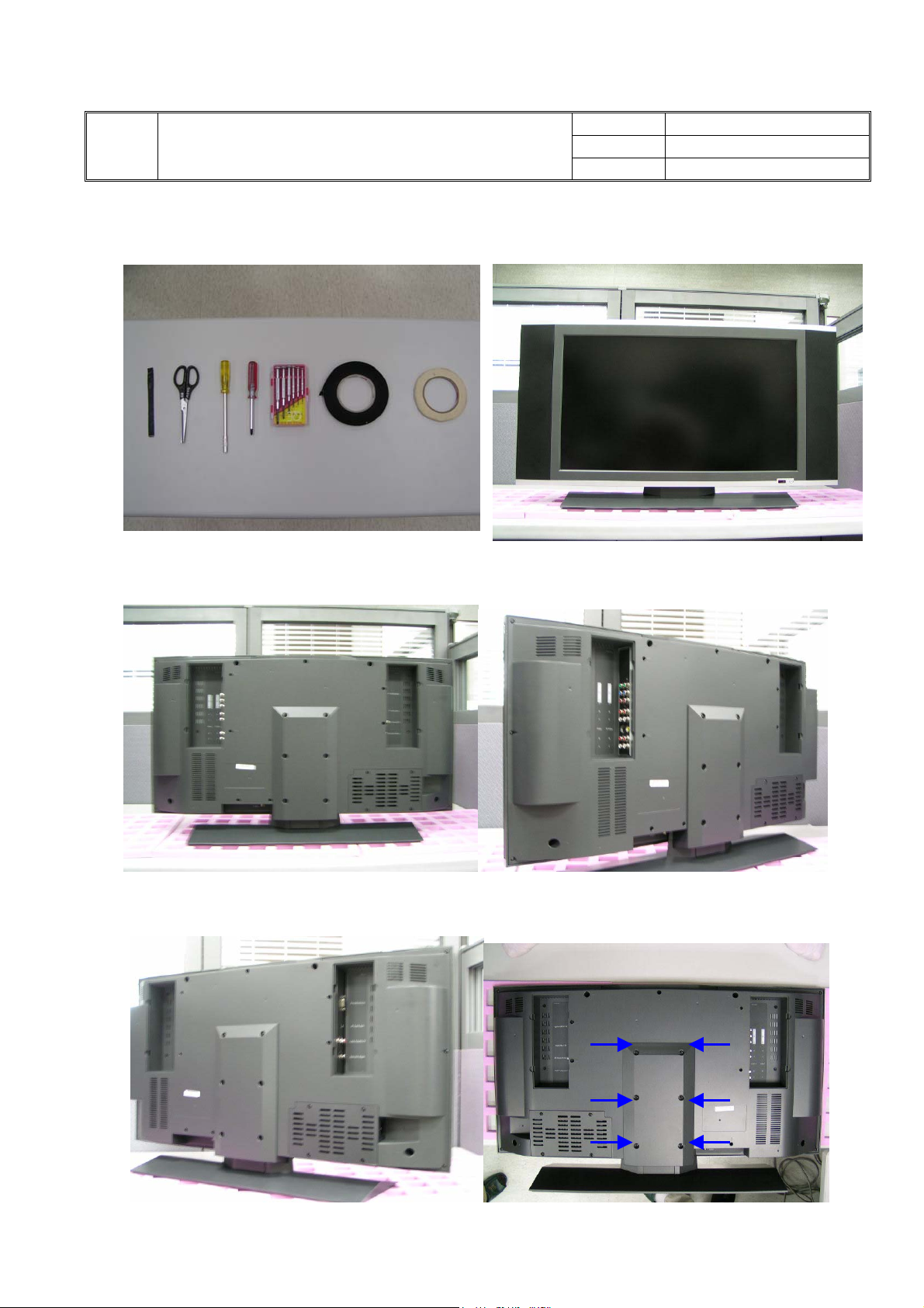
7.Disassembly/Assembly tools and procedure for 27”
Tools 1. 27”
Level 1 Service Manual
NO
VER. A1
PAGE
10/30
2. Back view 3. Lateral view
4. 5. Release 6 screws as arrow
10
Page 12

Nexgen Mediatech Inc.
NO
TITLE
6. Appearance of stand 7. Release 8 screws as arrows
Level 1 Service Manual
VER. A1
PAGE
11/30
8. Take of tuner box and AV box 9. Take off adaptor
10. AV box 11. Tuner Box
11
Page 13

Nexgen Mediatech Inc.
NO
TITLE
12. Release 15 screws as arrows 13. Take off wall mount bracket
Level 1 Service Manual
VER. A1
PAGE
12/30
14. Wall mount bracket 15. Loosen 8 screws on the speaker boxes.
16. Speaker boxes 17. Loosen 3 screws and take off speaker
cable.
12
Page 14

Nexgen Mediatech Inc.
NO
TITLE
18. Take off 4 screws and the pc panel bracket. 19. PC panel bracket.
Level 1 Service Manual
VER. A1
PAGE
13/30
20. Take off pc panel bracket. 21. Loosen 8 screws on main board.
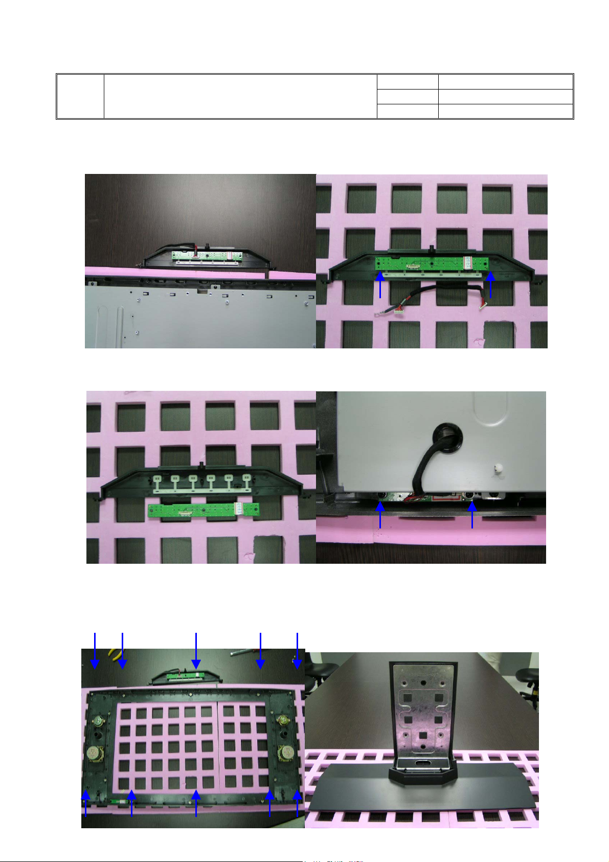
22. Disconnect 8 cables and take off 23. Loosen 2 screws on key pad
main board and disconnect two cable of inverter.
13
Page 15
Nexgen Mediatech Inc.
NO
TITLE
24. Take off Key pad set. 25. Release 2 screws on key pad.
Level 1 Service Manual
VER. A1
PAGE
14/30
26. Key pad board. 27. Loosen 2 screws on IR board.
28. Loosen 10 screws and separate front 29. Hinge and stand disassembly
14
Page 16

Nexgen Mediatech Inc.
TITLE
29-1 29-2
Level 1 Service Manual
NO
VER. A1
PAGE
15/30
29-3 29-4
29-5 29-6
15
Page 17

g
t
N
A
Nexgen Mediatech Inc.
NO
TITLE
Level 1 Service Manual
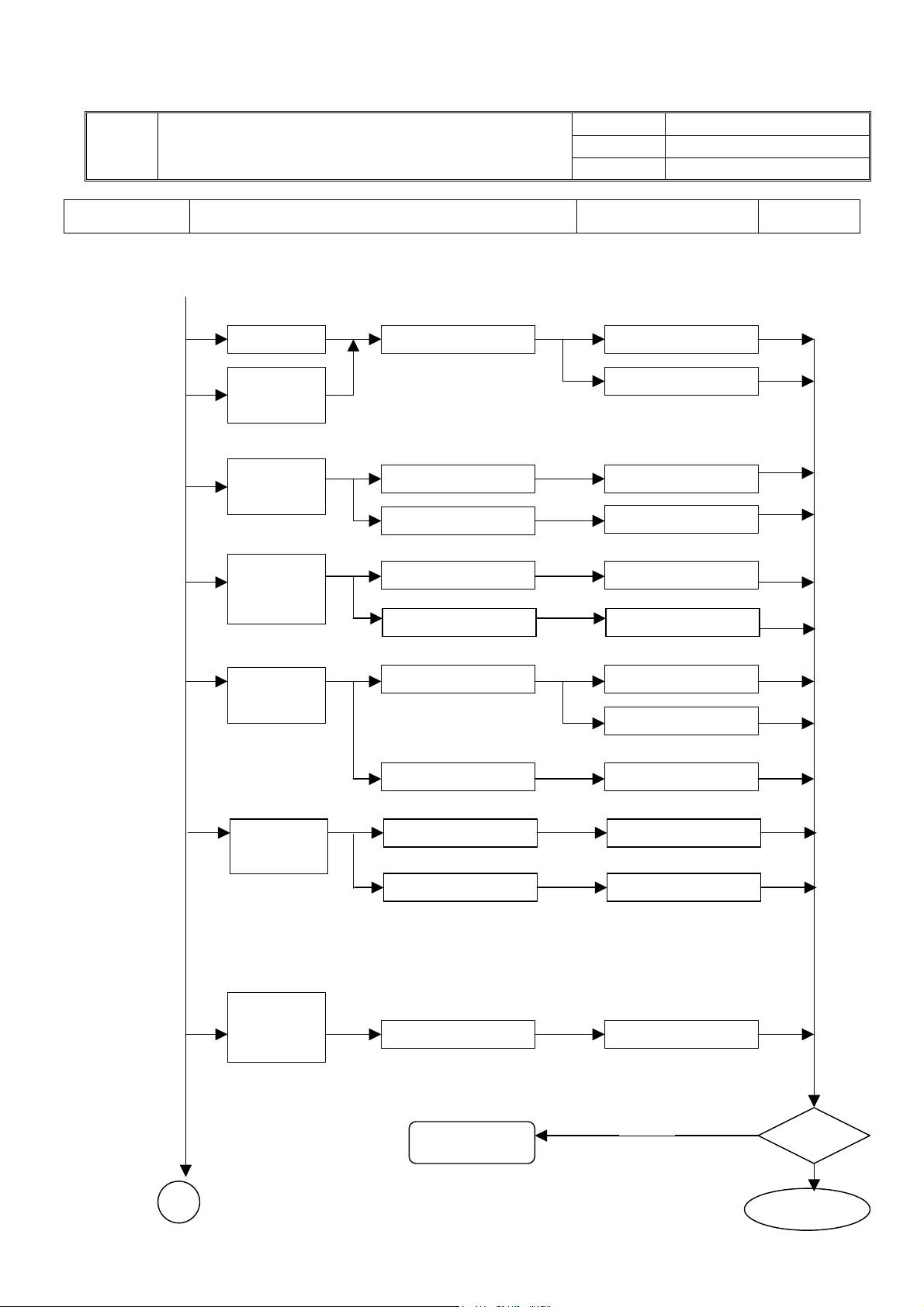
8.Troubleshooting Analysis
Defect Mode Failure Analysis Repair Testing
VER. A1
PAGE
16/30
Light On Test
Abnormal
Display
Missing Line Check PCB AD/B Change
Check Panel Panel Change
Bright Dot
Dark Dot
Backlight
Light Leakage
Mura Check Panel Panel Change
Image Stickin
Brightness spo
Particle
Dot Defect
No display
Check PCB AD/B Change
Inverter Change
Check Panel Panel Change
Check PCB AD/B Change
Check Panel Panel Change
G
Next Step
TEST
16
Complete
Page 18
n
g
A
Nexgen Mediatech Inc.
NO
TITLE
Level 1 Service Manual
Defect Mode Failure Analysis Repair Testing
Flicker Check PCB AD/B Change
VER. A1
PAGE
17/30
Image is
too dark
Inverter Change
Gray value
display
Check PCB AD/B Change
Check Panel
Panel Change
R. G. B
display
abnormal
Check PCB AD/B Change
Check Panel Cable Panel Cable Change
Display
Shut Down
Check PCB AD/B Cha
Inverter Change
e
Check Panel Panel Change
VGA No
Image
Check PCB AD/B Change
Check D-sub Cable D-sub Cable Change
Power on
Display
abnormal
Check PCB AD/B Change
Next Step
TEST
Complete
17
Page 19

N
y
p
Nexgen Mediatech Inc.
NO
TITLE
Level 1 Service Manual
Defect Mode Failure Analysis Repair Testing
ON/OFF
Abnormal
o Power Check PCB AD/B Change
VER. A1
PAGE
18/30
LED
display
abnormal
Keypad/B Change
Check FFC FCC Change
LED off
LED Dark Keypad/B Change
LED Abnormal
LED Flicker
Check PCB
Check FFC FCC Change
Power Saving Mode
in VGA
AD/B Change
Push Any Key
to Restart
Abnormal
Keyboard
Unavailable Check PCB
AD/B Change
Ke
ad/B Change
Check FFC
FFC Change
Next Step
TEST
18
Completed
Page 20

Nexgen Mediatech Inc.
NO
TITLE
Level 1 Service Manual
Defect Mode Failure Analysis Repair Testing
Other
Abnormal
Display
Display flicker
(tapping )
Check PCB AD/B Change
VER. A1
PAGE
19/30
Check Panel Inverter Change
Cannot use
remote control
Check keypad board Keypad Change
Check remote
Remote Control or
Battery Change
Check FFC FFC Change
Next Step
TEST
Completed
19
Page 21

N
r
Nexgen Mediatech Inc.
NO
TITLE
Level 1 Service Manual
Defect Mode Failure Analysis Repair Testing
Audio
Abnormal
Sound adjust
abnormal
Check PCB AD/B Change
o sound Check Speake
VER. A1
PAGE
Speaker Change
20/30
Check FCC FCC Change
Single sound Check PCB AD/B Change
Keypad/B Change
Hear phone
defect
Check hear phone
Jack
AD/B Change
Check FFC FCC Change
Check PCB
AD/B Change
TEST
Completed
20
Page 22

N
Nexgen Mediatech Inc.
NO
TITLE
Level 1 Service Manual
Defect Mode Failure Analysis Repair Testing
VER. A1
PAGE
21/30
Video
Abnormal
( AV , SV ,
CV , TV )
AV , SV , CV
o Image
TV No Image
TV No Sound
TV No Close
Caption
o
r V-Chip
(NTSC)
Check PCB AD/B Change
Check Cable Cable Change
Check PCB AD/B Change
Check RF Cable RF Cable Change
Check TV Module TV Module Change
Check PCB AD/B Change
Check TV Module TV Module Change
TV No
Teletext
( PAL ,
SECAM )
TEST
Completed
21
Page 23

Nexgen Mediatech Inc.
NO
TITLE
Level 1 Service Manual
Defect Mode Failure Analysis Repair Testing
VER. A1
PAGE
22/30
Abnormal
BIOS
Upgrade
Can’t Upgrade
BIOS
Check PCB AD/B Change
TEST
Completed
22
Page 24

Nexgen Mediatech Inc.
NO
TITLE
9 . Upgrade System Bios
Explanation of Programmable ISP (In System Program)
Use designed ISP tool to upgrade system BIOS. To press Ch- and Ch+ on key pad
simultaneously, to get into factory mode, to choose ISP item then change 0 to 1 by vol.
Pad.
9.1 Preparation before upgrade
Level 1 Service Manual
VER. A1
PAGE
23/30
Power switch
DC12(V)
9.2 Use RS-232 signal line to connect RS 232 OUT port of PC and the RS 232 IN PORT
of ISP tool. Use RGB signal line to connect VGA OUT port of ISP tool and VGA IN
port of LCD TV. Power on ISP tool, shown as below.
4. Power on
RS232 port
ISP port
(D-Sub15)
3. Plug in
DC power
supply
2. Connect to
VGA IN port
of LCD TV
9.3 The CPU used for processing ISP need to burn LD0415.BIN to the LDROM of CPU.
(Has burned before shipping)
Need to enter factory mode by pushing “747+enter” button on remote control to
9.4
execute ISP mode.
23
1. Connect to
RS232 OUT
port of PC
Page 25

Nexgen Mediatech Inc.
NO
TITLE
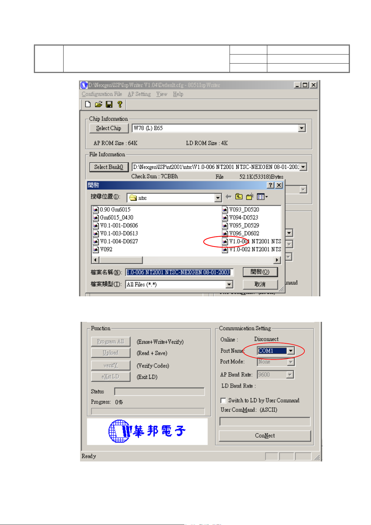
9.5 Execute ispwriter.exe file
To execute 8051IspWriter.exe file on your PC and the screen below appears.
Level 1 Service Manual
VER. A1
PAGE
24/30
9.6 Move the cursor to click “Select Chip” button and select the type of CPU(W78E65).
9.7 Move the cursor to click “Select Bank0” button to select the wanted burning program.
The file format is binary format instead of hex format.
24
Page 26
TITLE
Nexgen Mediatech Inc.
Level 1 Service Manual
NO
VER. A1
PAGE
25/30
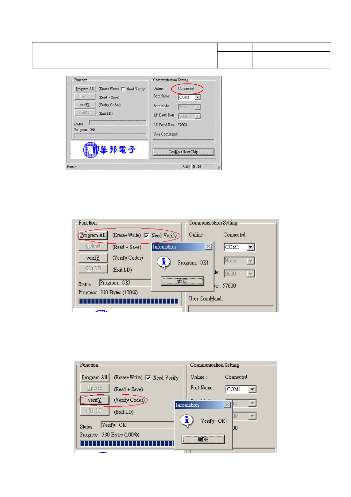
9.8 Select the Port name on Communication setting screen.
9.9 Move the cursor to click “Connect” button to link. If the linking succeeds, it will show
“Connected” on Communication Setting screen.
25
Page 27
TITLE
Nexgen Mediatech Inc.
Level 1 Service Manual
NO
VER. A1
PAGE
26/30
9.10 Click “Program All” button to execute erase and write function. After execution
screen below will appear. Click “confirm” button to finish the execution.
9.11 To click “verify” button to execute verify function. After verification screen below will
appear. Click “confirm” button to finish the verify function.
9.12 After updating EPROM program, disconnect ISP tool. Power on LCD TV again.
26
Page 28

Nexgen Mediatech Inc.
NO
TITLE
Level 1 Service Manual
10.Defect code, Possible Cause and Changed Parts summary
Items Defect mode Code Possible Cause and Changed Parts
1 No power F1 Power cord/adaptor, power supply, Keypad board, main board
2 No picture F2 Is on power saving mode? Each input signal is abnormal?
3 Missing line F3 Main board, panel, panel-MB cable
4 Bright/dark dot F4 Main board, panel, within dot spec
5 Abnormal Display F5 Frequency of input signal is normal, main board, Tuner
6 R. G. B display abnormal F6 Adjust Hue/Tint
7 Polarizer defect F7 Panel surface has scratch, crack or any surface defect?
8 Picture is too dark F8 Adjust brightness or contrast, inverter failure
VER. A1
PAGE
27/30
9 Audio Abnormal F9 Speaker, audio cable, Tuner
10 Audio/Video not clear F10 Signal frequency, fine tune RF frequency, tuner
11 Only sound, no picture F11 Signal frequency, fine tune channel frequency, tuner
12 Only picture, no sound F12 Signal frequency, fine tune channel frequency, tuner, speaker,
audio cable
13 Cannot use remote control F13 Battery, control angle smaller than 30 degree and 5 meter away
from the destination
14 Display Shut Down F14 Power supplier, keypad board, main board
15 No picture F15 Adjust hue/tint, main board
16 No TV picture or picture is
unclear
17 Flicker F17 Input signal not stable, inverter, main board
18 TV No Teletext ( PAL ,
SECAM )
19 NTSC SAP/MTS failure F19 Tuner, main board, firmware
20 Appearance and
mechanism
F16 TV cable, RF signal frequency, the direction of
antenna, main board
F18 TV module, main board, firmware
F20
21 Others F21 Please attach electronic picture and explain
27
Page 29
Nexgen Mediatech Inc.
TITLE
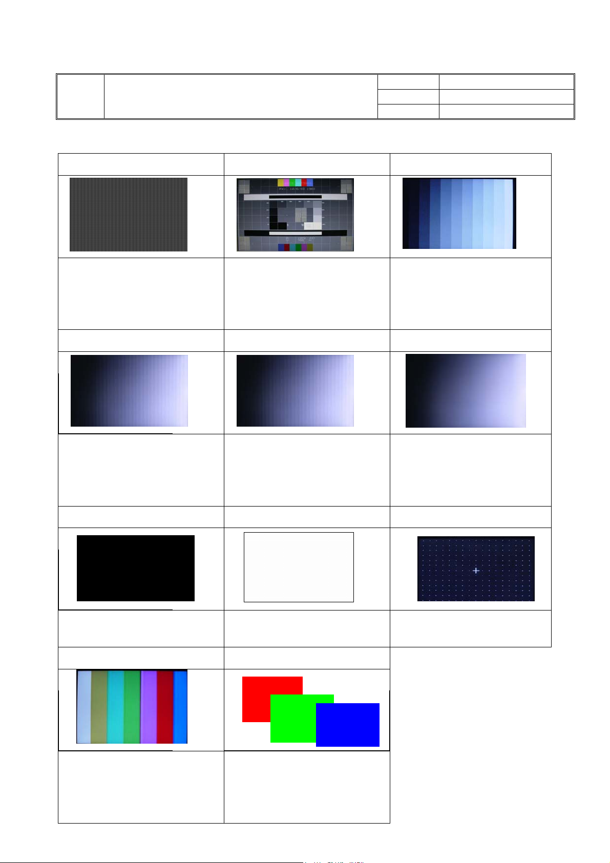
11.Test patterns and check points
1 Dot on/off SMPTE RP133 16 Gray scale
Level 1 Service Manual
NO
VER. A1
PAGE
28/30
*Check if Clock & Phase is
distorted.
32 Gray scale 64 Gray scale 256 Gray scale
*Check the amplitude of RF signal is
distorted
*Check the gray scale is over
saturated.
Black White 1 Dot on/off
*Check if vertical line and horizontal
line is clear around the center,
four corners
*Check brightness and contrast
*Check the amplitude of RF signal is
distorted
*Check the gray scale is over
saturated.
*Check the amplitude of RF signal
is distorted.
*Check the gray scale is over
saturated.
*Check the amplitude of RF signal
is distorted
*Check the gray scale is over
saturated.
*Check noise, leakage, ghost
*Check pixel bright/dark dot.
*Check noise, leakage, ghost image
*Check pixel bright/dark dot.
*Check static convergence
Color R、G、B
*Check color quality, decoding
,color transformation, chroma
/hue/tint time equalization, color
saturation.
28
*Check pixel bright/dark dot.
*Check color quality
Page 30
Nexgen Mediatech Inc.
TITLE
12.Remark (SPARE PARTS LIST)
Material Item S/N Item
Level 1 Service Manual
NO
VER. A1
PAGE
29/30
Key parts
PCBA
Accessory
Internal cable
Packing meterial
Mechanical parts
180-270001-101 PANEL LCD 27" WXGA 1280*720
185-115001-101 ADAPTER 150W 12V
196-270001-101 NLC27C1 INVERTER VER5.0
510-271003-011 NLC27C1 MAIN BOARD PCBA VER.1
510-272002-011 PCBA NLC27C1 IR BOARD
510-272003-011 PCBA NLC27C1 KEY BOARD
170-041801-101 P-CORD 250V 10A EU 3P BLK 1.8M
171-071801-101 CAB VGA 15P BLACK 28AWG 1.8M
174-270302-101 WIRE W/B 27 SPK-L 3PIN L=650MM
174-270301-101 WIRE 27" SPK-R 3PIN L=750MM
174-270601-101 WIRE 27" IR 6PIN L=420MM
174-270602-101 WIRE 27" POWER 6PIN L=200MM
174-271001-101 WIRE 27" KEYPAD 10PIN L=150MM
174-272201-101 WIRE 27" INVERTER 22PIN L=250
174-273001-101 WIRE W/B NLC27C1 30PIN L=60MM
401-270003-021 T27001 MAIN CARTON LUXOR
403-270005-011 EPE CUSHING STAND NECK
403-270007-011 NLC27C1 EPE CUSHING TOP
403-270008-011 NLC27C1 EPE CUSHING BOTTOM
A44-L27C9-001 NLC27C1 EPE BAG
240-420001-011 CARTON LOCK
154-050402-101 SPK 5W 4R
154-050802-101 SPK 5W 8R 57*55*38 FULL RANGE
154-100004-101 SPK 5W 8R
462-270001-011 T27001 LOGO FOR DIXONS
200-270001-0101 NLC27C2 FRONT BEZEL
200-270003-0101 NLC27C1 ADAPTOR COVER
200-270004-0101 NLC27C1 AV COVER
200-270005-0101 NLC27C1 PC COVER
200-270006-0101 NLC27C1 BACK COVER
200-270007-0101 NLC27C1 STAND BASE COVER
200-270009-0101 NLC27C1 STAND FRAME COVER
200-270010-0101 NLC27C1 LIGHT GUIDE
200-270011-0101 NLC27C1 POWER BUTTON
200-270012-0101 NLC27C1 FUNCTION KEY
200-270013-0101 NLC27C1 IR FILTER
29
Page 31
TITLE
Nexgen Mediatech Inc.
Level 1 Service Manual
Screw
200-270014-0101 NLC27C1 SPEAK BOX
200-270015-0101 NLC27C1 FUNCTION PANEL
200-270017-0101 NLC27C1 STAND FRAME PLATE
210-270007-011 NLC27C1 PC NAME PLATE
250-270007-011 NLC27C1 MAIN COVER BRACKET
250-270008-011 NLC27C1 PANEL BRACKET
250-270009-011 NLC27C1 PC PANEL BRACKET
250-270010-011 NLC27C1 SPEAKER NET
250-270011-011 NLC27C1 STAND BASE BRACKET
250-270012-011 NLC27C1 STAND FRAME BRACKET
250-270016-011 NLC27C1 WALL MOUNT BRACKET
600-030004-010 SCREW M4*12 PAN HEAD
600-030008-041 SCREW M3*8 PAN HEAD
600-040008-040 SCREW M4*8 PAN HEAD
600-440012-110 SCREW M4*12MM PAN HEAD
600-740008-040 SCREW T4*8 PAN HEAD TP-P
600-740012-040 SCREW T4*12 P-HEAD
601-730008-040 SCREW T3*8 TP-P BINDING HEAD
602-030006-010 SCREW M3*6 PAN/WAS-HEAD
602-730008-010 SCREW T3*8 PHW TP-P
602-740008-010 SCREW T4*8 PHW TP-P
603-040008-040 SCREW M4*8 I-HEAD
605-140007-010 SCREW HEX 4#-40*7
608-730010-030 SCREW T3*10 TP-P PH+W(10)
609-020005-030 SCREW M2*5 PH+SW+W
609-140015-040 SCREW M4*15 PH+SW+W
NO
VER. A1
PAGE
30/30
30
 Loading...