

Page 1
1 | EN
DOUBLE BUILT IN OVEN SERVICE
MANUAL
Page 2

2 | EN
1.COVER
2.INDEX
1. COVER
2.INDEX
1.COVER ...................................................................................................................................... 2
3. SAFETY WARNING .................................................................................................................... 5
3.1 GENERAL SAFETY ............................................................................................................................... 5
3.2. SAFETY FOR CONFİGURATİONS ............................................................................................................. 5
3.3 INFORMATİONS FOR CONSUMER ........................................................................................................... 6
4. TECHNICAL SPECIFICATIONS ..................................................................................................... 7
5. PRODUCT ASSEMBLY/ ASSEMBLY RULES/ SETTINGS ................................................................. 8
5.1 PRODUCT TRANSPORTATION ................................................................................................................ 8
5.2 UNPACKING PRODUCT ........................................................................................................................ 9
5.3 CONTROLLING THE SETUP PLACE AND ENERGY SOURCES ........................................................................... 11
5.3.1 Measurement control of the mounting place ...................................................................... 11
5.4 ELECTRİCAL CONNECTİON ................................................................................................................... 12
6. USE OF PRODUCTS ................................................................................................................. 13
6.1 OPERATING FUNCTIONS ..................................................................................................................... 13
6.3 USE OF PRODUCT HOURS .................................................................................................................. 15
6.3.1 Digital clock products (6 keys) .............................................................................................. 15
Using the oven clock ...................................................................................................................... 17
Using the clock as an alarm .......................................................................................................... 25
6.3.2 Adora clock products ............................................................................................................ 27
7.BY PRODUCTS/PRODUCTS LABELS USED .................................................................................. 37
7.1 ACCESSORIES ................................................................................................................................... 37
7.2 TAGS AND DESCRIPTIONS USED IN THE PRODUCT .................................................................................... 38
7.2.1 Type the label ....................................................................................................................... 38
7.2.2 Barcode Label ....................................................................................................................... 39
7.3.3 Energy Label ......................................................................................................................... 39
8. GENERAL WORKING PRINCIPLE ............................................................................................... 41
9. LIST OF COMPONENTS / COMPONENT WORKING PRINCIPLE................................................... 42
9.1 TECHNICAL SPECIFICATIONS OF THE COMPONENTS; ................................................................................. 42
10. FAULT FLOW / FAULT FINDING DIAGRAMS ........................................................................... 44
10.1.RESİSTANCE FAULTS ....................................................................................................................... 44
10.1.1 Resistance does not work;the food is not cooked .............................................................. 44
10.2 LAMP FAULT ................................................................................................................................. 45
10.2.1 Furnace is working but the oven does not illuminate ........................................................ 45
10.2.2 Oven does not work,oven lamp does not light, .................................................................. 46
10.3 TERMOSTAT FAULT ......................................................................................................................... 47
10.3.1 Furnace runs continuosly,the thermostat is not tripped. ................................................... 47
Page 3

3 | EN
10.4 THERMİNAL FAULT ......................................................................................................................... 48
10.4.1There is no power from the terminal does not diffuse into the electric furnace ................ 48
10.4.2 When the fuse blows the oven is plugged into the Wall socket. ........................................ 49
12. COMPONENT ASSEMBLY / DISASSEMBLY BE USED IN EQUIPMENT ........................................ 52
13.COMPONENT ASSEMBLY / DİSASSEMBLY............................................................................... 53
13.1 REPLACEMENT OF THE KNOB ............................................................................................................. 53
13.2 REPLACEMENT OF THE UPPER COVER SHEET ......................................................................................... 53
13.3 REPLACEMENT OF THE CONTROL PANEL .............................................................................................. 54
13.4 REPLACEMENT OF THE FRONT DOOR ................................................................................................... 56
13.5 REPLACEMENT THE FRONT DOOR HINGE .............................................................................................. 57
13.6 REPLACEMENT OF THE REMOVABLE GLASS COVER 3 ............................................................................... 58
13.7 REPLACEMENT OF THE REMOVABLE GLASS COVER 2 ............................................................................... 60
13.8 REPLACEMENT OF THE REMOVABLE GLASS COVER 4 ............................................................................... 65
13.9 REPLACEMENT OF THE HANDLE ......................................................................................................... 68
13.10 REPLACEMENT OF THE COMUTATORS ............................................................................................... 69
13.11 REPLACEMENT OF THE OVEN THERMOSTAT ........................................................................................ 70
13.12 REPLACEMENT OF THE THERMOSTAT BULB......................................................................................... 71
13.13 REPLACEMENT OF THE Bİ-METAL THERMOSTAT .................................................................................. 73
13.14 REPLACEMENT OF THE ENGINE COOLING ........................................................................................... 73
13.15 REPLACEMENT OF THE VENTILATION PLATE ........................................................................................ 74
13.16 REPLACEMENT OF THE VENTILATION THERMOSTAT .............................................................................. 75
13.17 REPLACEMENT OF THE REAR COVER SHEET ......................................................................................... 77
13.18 REPLACEMENT OF THE SIDE WALLS .................................................................................................. 78
13.19 REPLACEMENT OF THE BOTTOM PLATE .............................................................................................. 79
13.20 REPLACEMENT OF THE SWİTCH ........................................................................................................ 80
13.21 REPLACEMENT OF CATALIYTIC SIDE WALLS ......................................................................................... 82
13.22 REPLACEMENT OF TOP HEATİNG ELEMENT ......................................................................................... 83
13.23 REPLACEMENT OF THE BOTTOM HEATİNG ELEMENT ............................................................................ 85
13.24 REPLACEMENT OF THE RING HEATER ................................................................................................. 86
13.25 REPLACEMENT OF THE SEAL OVEN .................................................................................................... 88
13.26 REPLACEMENT OF THE TURBO MOTOR .............................................................................................. 89
13.27 REPLACEMENT OF THE TERMINAL BOX .............................................................................................. 91
13.28 REPLACING THE RUNNERS .............................................................................................................. 93
13.29 REPLACING THE OVEN LAMP ........................................................................................................... 93
13.30 REPLACEMENT OF THE OVEN SQUARE LAMP ...................................................................................... 94
13.31 REPLACEMENT OF THE SİGNAL LAMP ................................................................................................ 95
13.32 REPLACEMENT OF THE GLASS WOOL ............................................................................................... 96
13.33 REPLACEMENT OF THE 6 BUTTON HOURS .......................................................................................... 98
13.34 REPLACEMENT OF THE ADORA TIMER ............................................................................................... 99
14. PYRO OVEN SPECIFICATIONS ASSEMBLY / DİSASSEMBLY .................................................... 102
14.1 ISOLATION SHEET METAL CONNECTION ............................................................................................. 102
14.2 DISPLACEMENT OF CATALYSOR ....................................................................................................... 103
14.3 REPLACEMENT DOOR LOCK ............................................................................................................. 103
14.3 REPLACEMENT OF THE VENTILATION SHEET ........................................................................................ 105
14.3 REPLACEMENT OF THE PYRO VENTİLATİON SHEET METAL....................................................................... 107
Page 4

4 | EN
14.4 CHANGING THE PYRO COOLING ENGINES ........................................................................................... 107
14.5 REPLACING THE ENGINE COOLING THERMOSTAT ................................................................................. 108
Page 5
5 | EN
3. SAFETY WARNING
This section contains safety instructions that will help protect from risk of personal
injury or property damage.
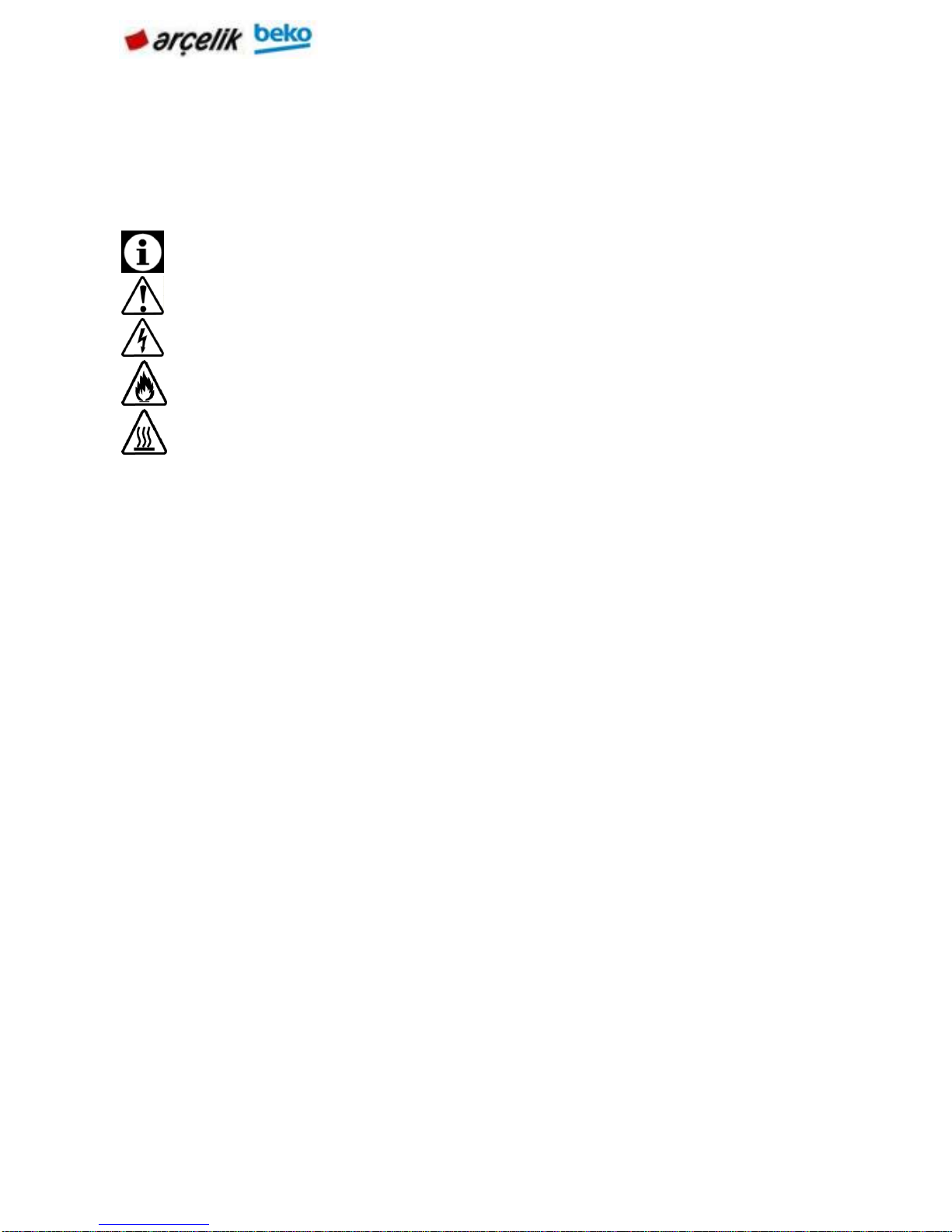
Throughout this user manual the following symbols are used.
Important information or useful hints about usage.
Warning of hazardous situations with regard to life and property.
Warning of electric shock..
Warning of risk of fire.
Warning of hot surfaces.
3.1 General Safety
• This appliance can be used by children aged from 8 years and above and
persons with reduced physical, sensory or mental capabilities or lack of
experience and knowledge if they have been given supervision or instruction
concerning use of the appliance in a safe way and understand the hazards
involved.
Children shall not play with the appliance. Cleaning and user maintenance shall
not be made by children without supervision.
• Installation and repair procedures must always be performed by Authorized
Service Agents. The manufacturer shall not be held responsible for damages
arising from procedures carried out by unauthorized persons which may also void
the warranty. Before installation, read the instructions carefully.
• Do not operate the product if it is defective or has any visible damage.
Control that the product function knobs are switched off after every use.
3.2. Safety for Configurations
Control the area of the configuration is appropriate.
It is important that sources of energy is near the product.
Do not lay the network wire on the hot surface.If not wire coalasces and this couses
short circuit.
Be cafeful during the configuration wire is not cut or deformed.If not change them with
new one.
There is not a component to release the gases resulting of the burning in the
product.Set up the product according to the configuration rules.Especially,be careful
with the airing tools and needs.
Page 6

6 | EN
3.3 Informations for Consumer
Product may be hot during the usage.Do not touch with hot parts ,inside the
oven,heating components etc. .When the product is working it is hot so do not put
combustable materials near the product.
Do not wash the product with water! It is dangerous for electrick shock!Ürünü, üzerine s
Do not heat the closed preserve jar or can with the product.Presure may cause the
explosion.
Do not clean while the product is working.
Do not change in anything on the porduct or any repair instead of some problems in the
user guide.
If there is no door or window for airing ,blower must be built.
Use a glove that is heat resistant during put/remove the meal to the hot oven
Do not use the product if front glass is broken or removed or any deformation on the
tweel block.
When tweel block is open, be careful about children do not sit down on it.
Do not hang cloth or towel or something like them on handle.
Page 7

7 | EN
4. TECHNICAL SPECIFICATIONS
Refer to the product specifications manusoft.
Page 8
8 | EN
5. PRODUCT ASSEMBLY/ ASSEMBLY RULES/ SETTINGS
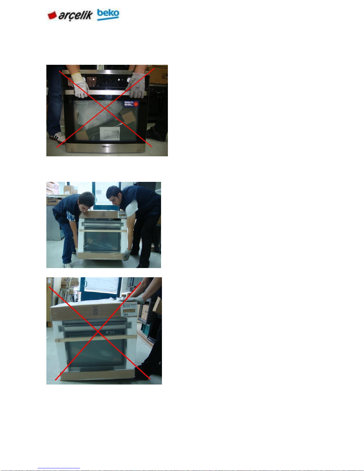
5.1 Product Transportation
Control the view of the product for any damage which may occur in the carrying period.
To carry or move the product, do not use
door or handle of the product. Door,
handle or hinges can be harmed.
Product should be carried by two person for
safety of the product and ergonomics
When the product is being carried or the
product is being put to the ground, do not put it
keenly, do not drag it and do not skid it from
stairs.
Page 9
9 | EN
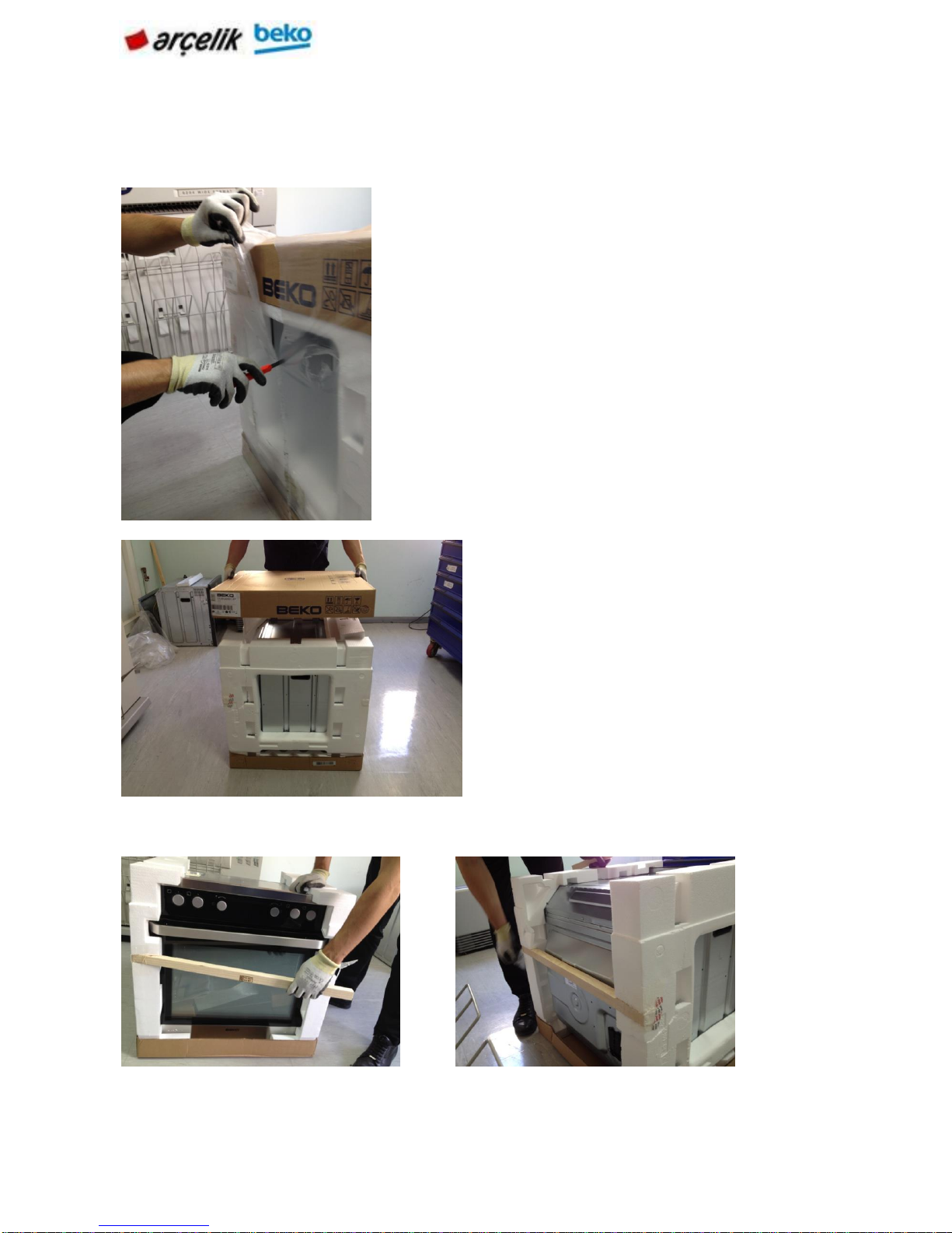
5.2 Unpacking Product
To consider product changing in the mounting process, please do not harm package,
product and the product package when extracting.
Take lathes on the product’s front and behind sides, like shown in below.
Extract package with a knife without harming top
and bottom carton.
Take the top carton.
Page 10

10 | EN
Symbols on the package of the products and meaning of them;
Preserve
from damp
Fragile
Carry with
barrow in
this way.
Do not carry
the product
like in the
picture
Carry the product
in this way by
squeezing with
clamp
Do not step on
the product.
Take stripers which are left and
right side of the products.
Page 11

11 | EN
5.3 Controlling the setup place and energy sources
5.3.1 Measurement control of the mounting place
In the setup of the product, local standards about electric and gas should be applied.
Product is designed according to kitchens’ bench so it is placeable. Appropriate safety
interval should be between kitchen wall and the furniture. For appropriate interval, please
look at the picture.(values are mm type).
Used sides, synthetic laminates and glues should be durable to the head (min.100°C).
Product should be stayed with the same height with kitchen furnitures.
If there is a drawer bottom of the oven, a shelf should be used between oven and the
drawer.
Page 12
12 | EN
5.4 Electrical connection
Connect the product to a grounded outlet/line protected by a fuse of suitable capacity as
stated in the "Technical specifications" table. Have the grounding installation made by a
qualified electrician while using the product with or without a transformer. Our company
shall not be liable for any damages that will arise due to using the product without a
grounding installation in accordance with the local regulations.
Connection must comply with national regulations.
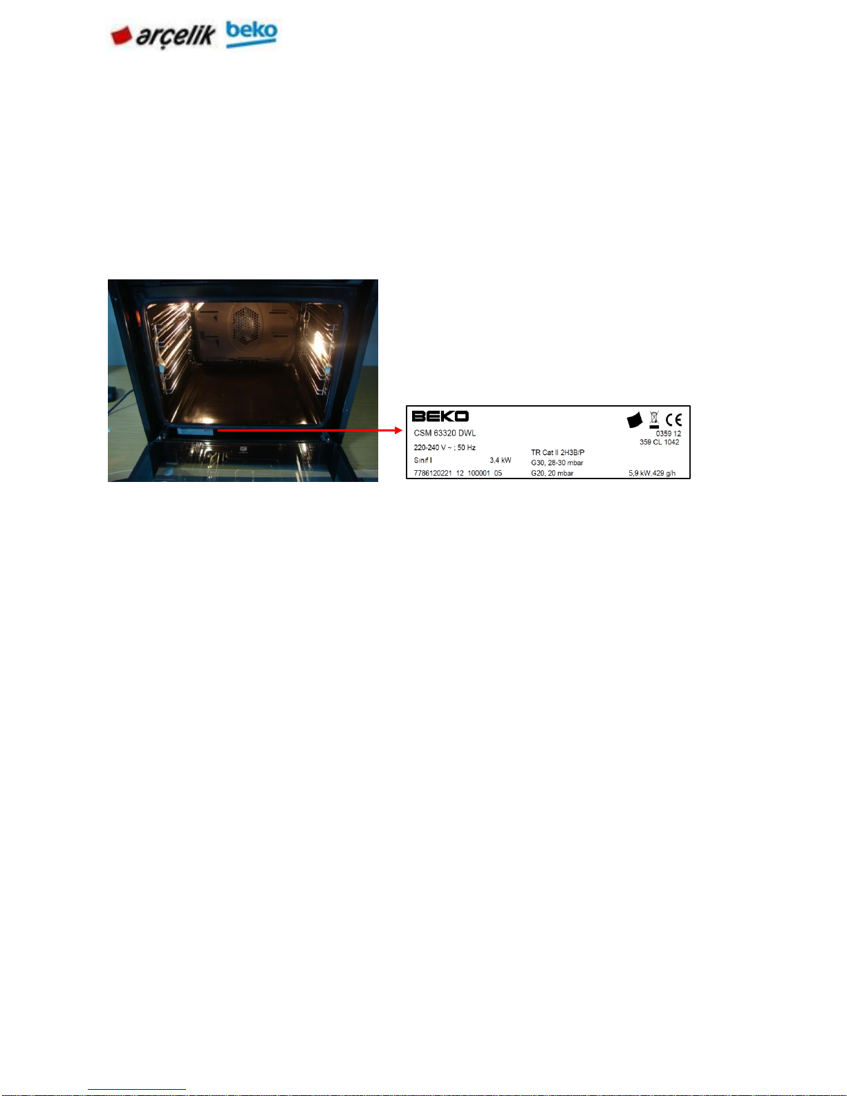
The mains supply data must correspond to the data specified on the type label of the
product.
Open the front door to see the type label.
Page 13
13 | EN
6. USE OF PRODUCTS
6.1 Operating functions
The sequence of operating modes shown here may differ from the arrangement on your
appliance.
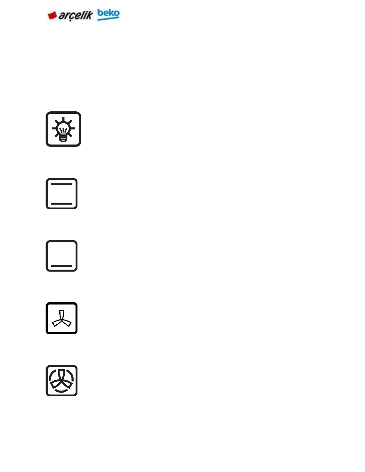
Oven lamp
Top and bottom heating
Bottom heating
Operating with fan
Fan Heating
The oven is not heated. Only the oven lamp is turned on.
Possibly, the external cooling fan will also operate to avoid
heating of the compartments.
Top and bottom heating are in operation. Food is heated
simultaneously from the top and bottom. For example, it is
suitable for cakes, pastries, or cakes and casseroles in baking
moulds. Cook with one tray only.
Only bottom heating is in operation. It is
suitable for pizza and for subsequent browning
of food from the bottom.
The oven is not heated. Only the fan (in the rear wall) is in
operation. Suitable for thawing frozen granular food slowly at
room temperature and cooling down the cooked food.
Warm air heated by the rear heater is evenly distributed
throughout the oven rapidly by means of the fan. It is
suitable for cooking your meals in different rack levels and
preheating is not required in most cases. Suitable for
cooking with multi trays.
Page 14
14 | EN
Grill
Full grill
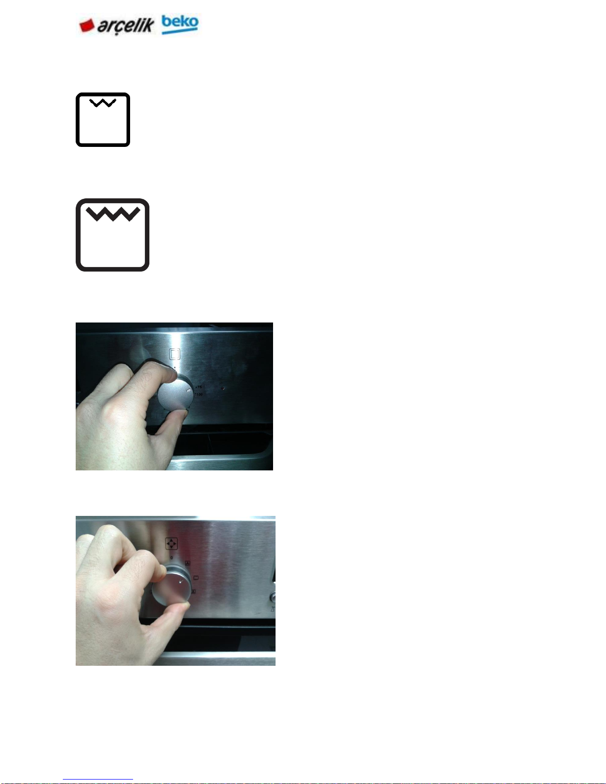
6.2 Selection of the temperature and operating mode
Small grill at the ceiling of the oven is in operation. Suitable
for grilling.
• Put small or medium-sized portions in correct shelf
position under the grill heater for grilling.
• Set the temperature to maximum level.
Turn the food after half of the grilling time.
Large grill at the ceiling of the oven is in operation. It is
suitable for grilling large amount of meat.
• Put big or medium-sized portions in correct rack position
under the grill heater for grilling.
• Set the temperature to maximum level.
• Turn the food after half of the grilling time.
Turn the thermostat knob to the
desired temperature.
Set the function switch to the
desired operating mode.
Page 15
15 | EN
The oven heats up to the set temperature and maintains this temperature. During heating,
temperature lamp illuminates.
Turning off the electric oven
6.3 Use of Product Hours
6.3.1 Digital clock products (6 keys)
Plug in the power cord and turn on the insurance of the device. You need to make the
language setting before making.
NOTE: Any value you set is automatically saved when you exit the menu you are in.
NOTE: Before using the oven, adjust the time.
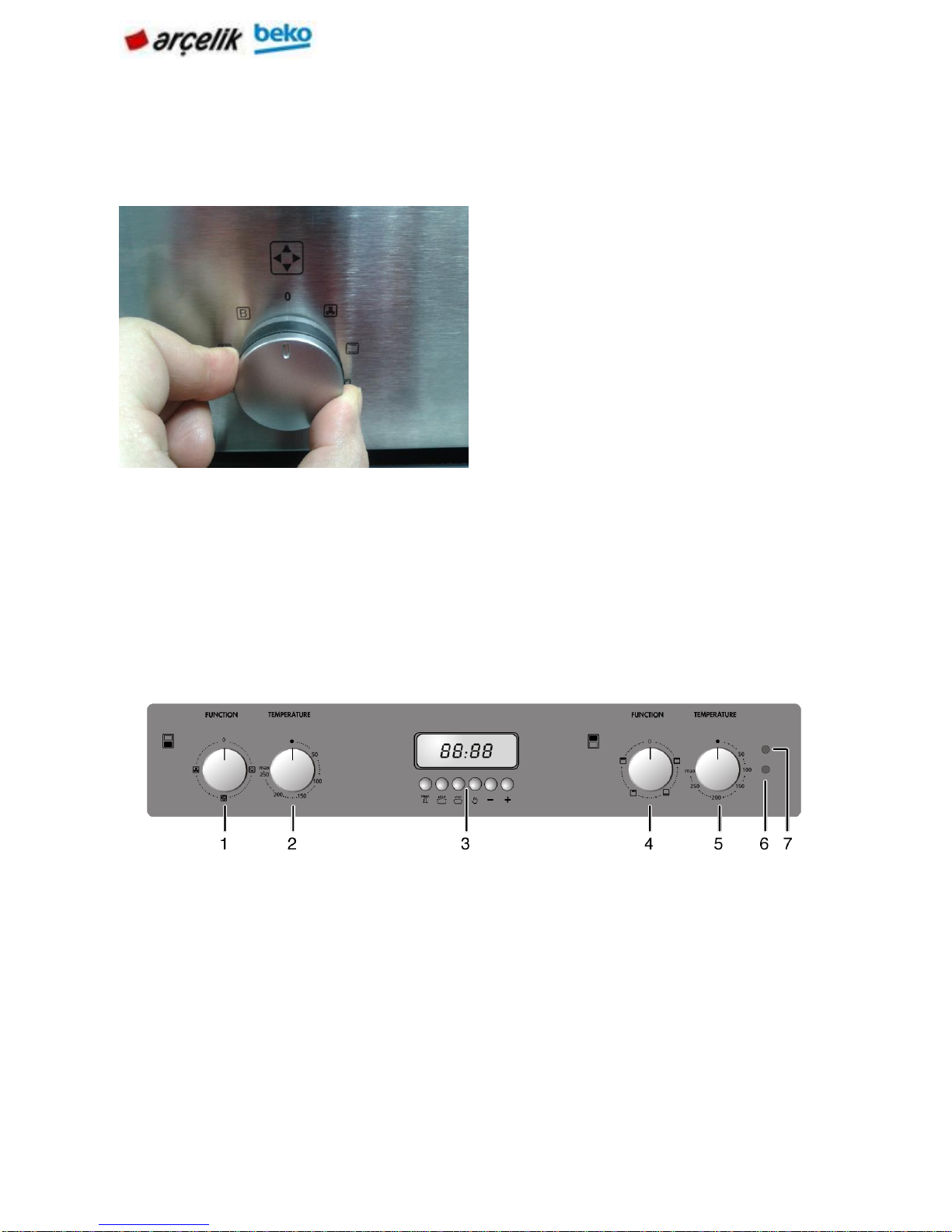
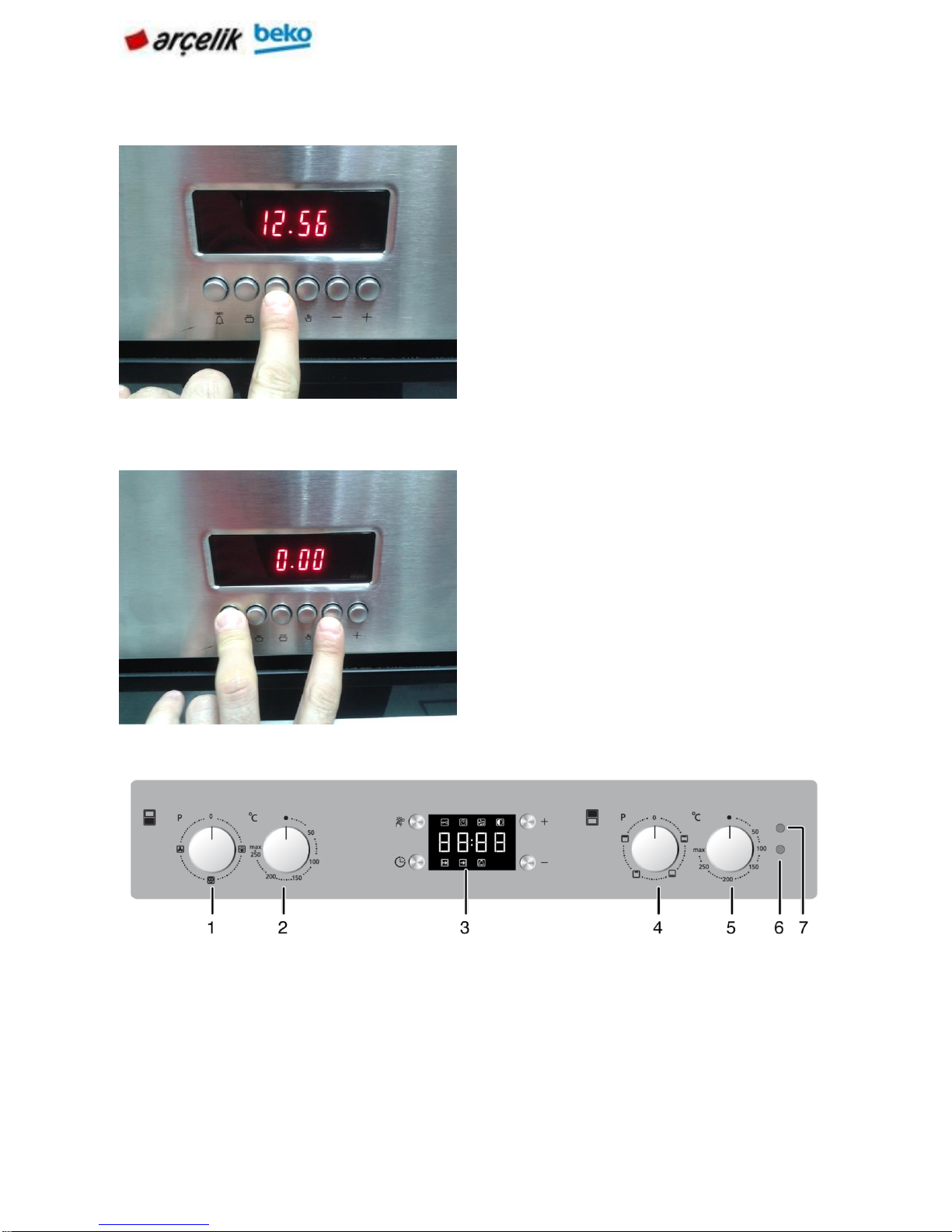
1
Main oven function knob
2
Main oven thermostat knob
3
Digital timer
4
Top oven function knob
5
Top oven thermostat knob
6
Thermostat lamp for main oven
7
Thermostat lamp for top oven
Function button and the
temperature knob off (upper)
position.
Page 16
16 | EN
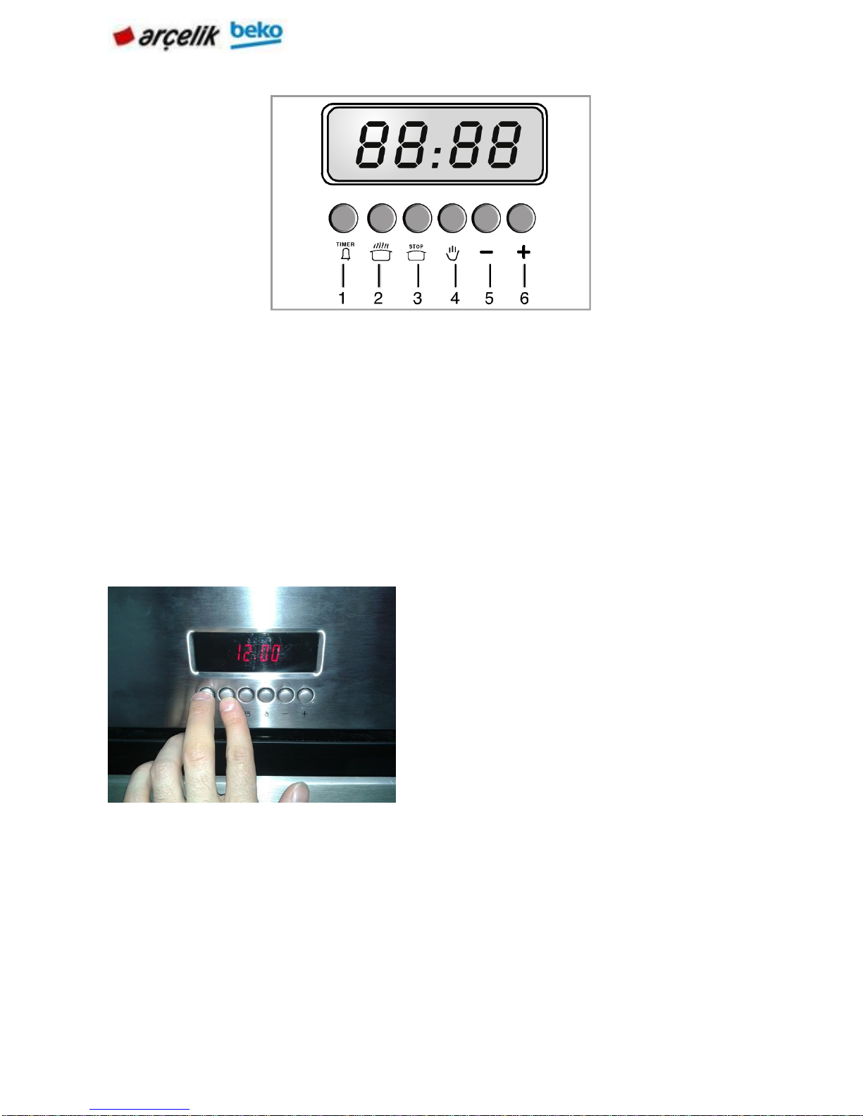
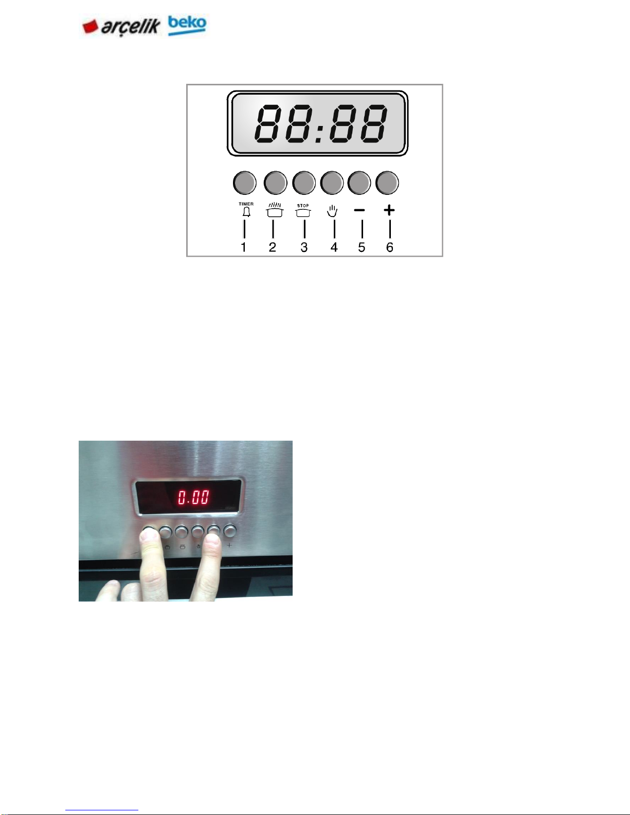
Keys:
1
Alarm key
2
Cooking time
3
End of cooking time
4
Unscheduled cooking
Time adjustment keys:
5
Minus key
6
Plus key
Keep keys (1) and (2) pressed.
Page 17
17 | EN
Using the oven clock
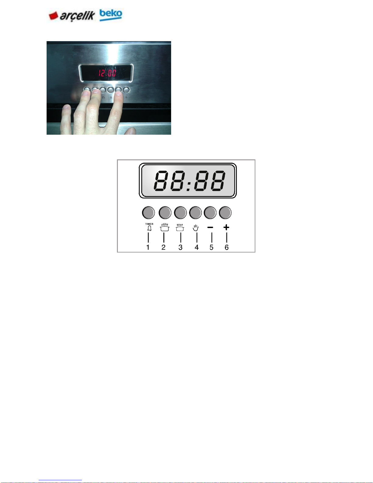
Keys:
1
Alarm key
2
Cooking time
3
End of cooking time
4
Unscheduled cooking
Time adjustment keys:
5
Minus key
6
Plus key
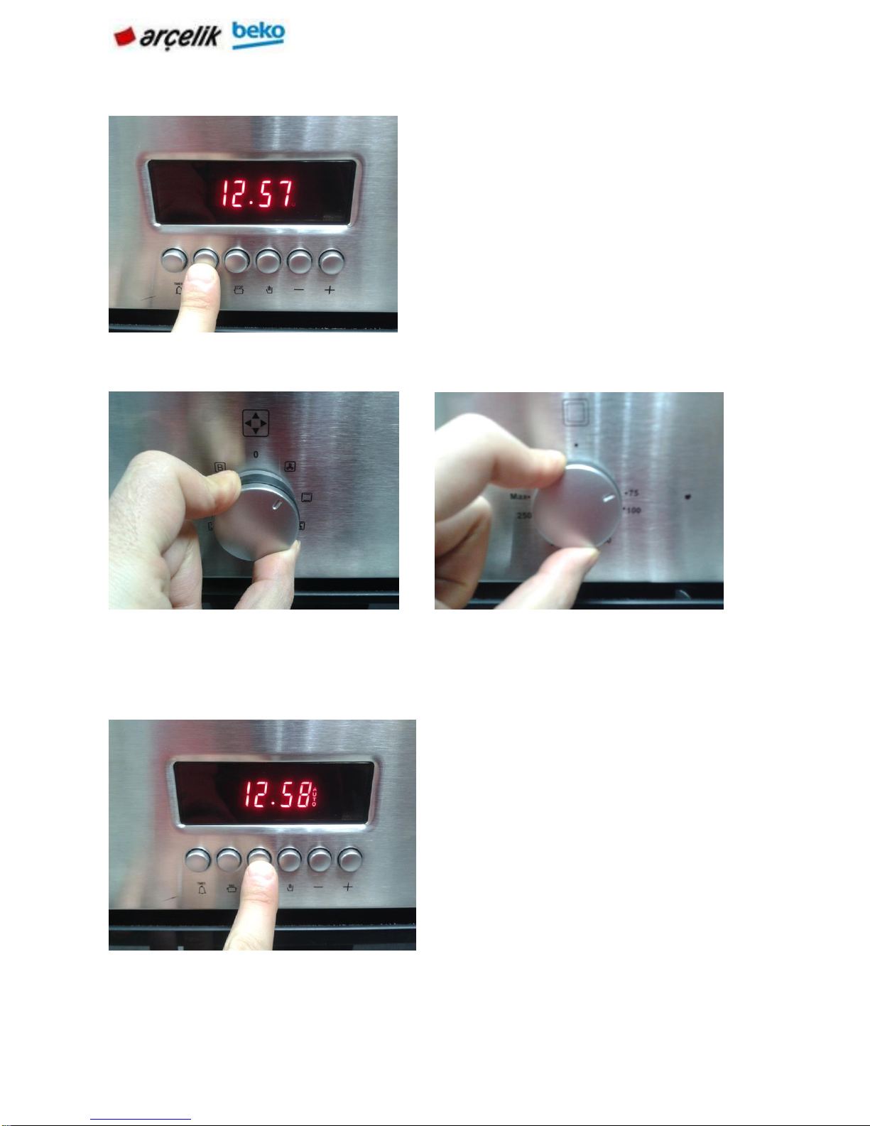
Switch on fully automatic operation
In this operation mode you can enter the cooking time after entering the end of cooking
time. Oven will calculate the time to start cooking and it will operate automatically at the
designated time.
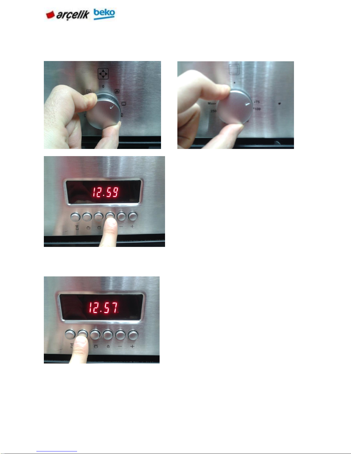
Press (5) or (6) keys to set the time.
Press the key with short intervals to
increase or reset the time with
increments of 1 minute. If you keep
the relevant key pressed, the minutes
will increase and reset faster.
Page 18
18 | EN
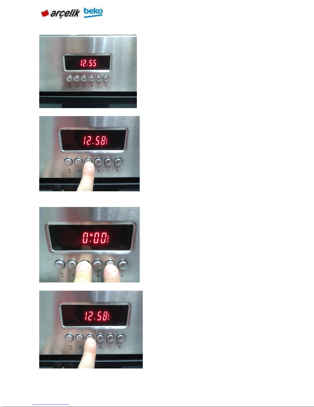
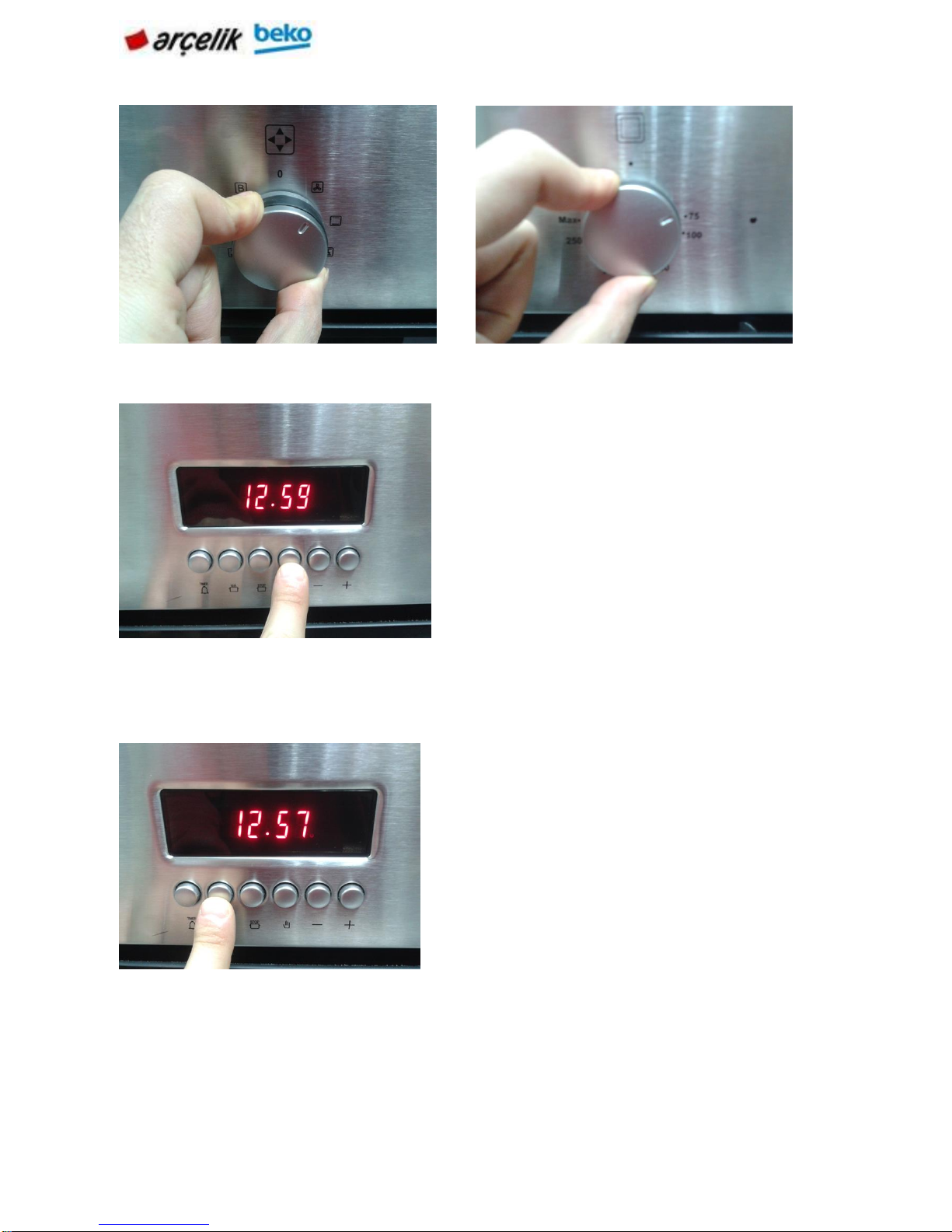
Make sure that the clock is correct. Put
your dish into the oven and close the
door.
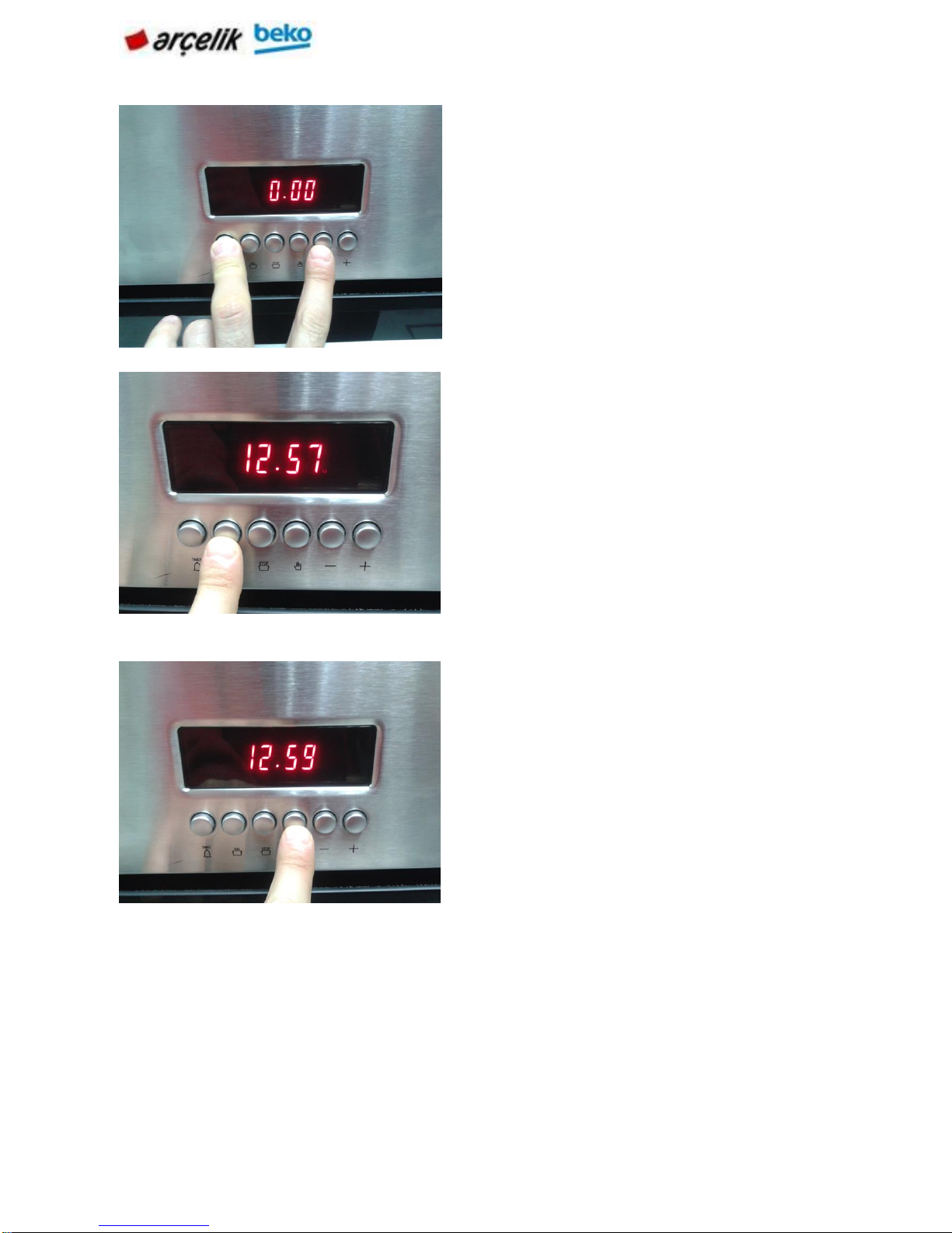
Keep the key (3) pressed.
Press (5) or (6) keys to set the end of
cooking time. Press the key with short
intervals to increase or reset the time
with increments of 1 minute. If you keep
the key pressed, the minutes will
increase and reset faster
AUTO symbol appears on the
display.
Page 19
19 | EN
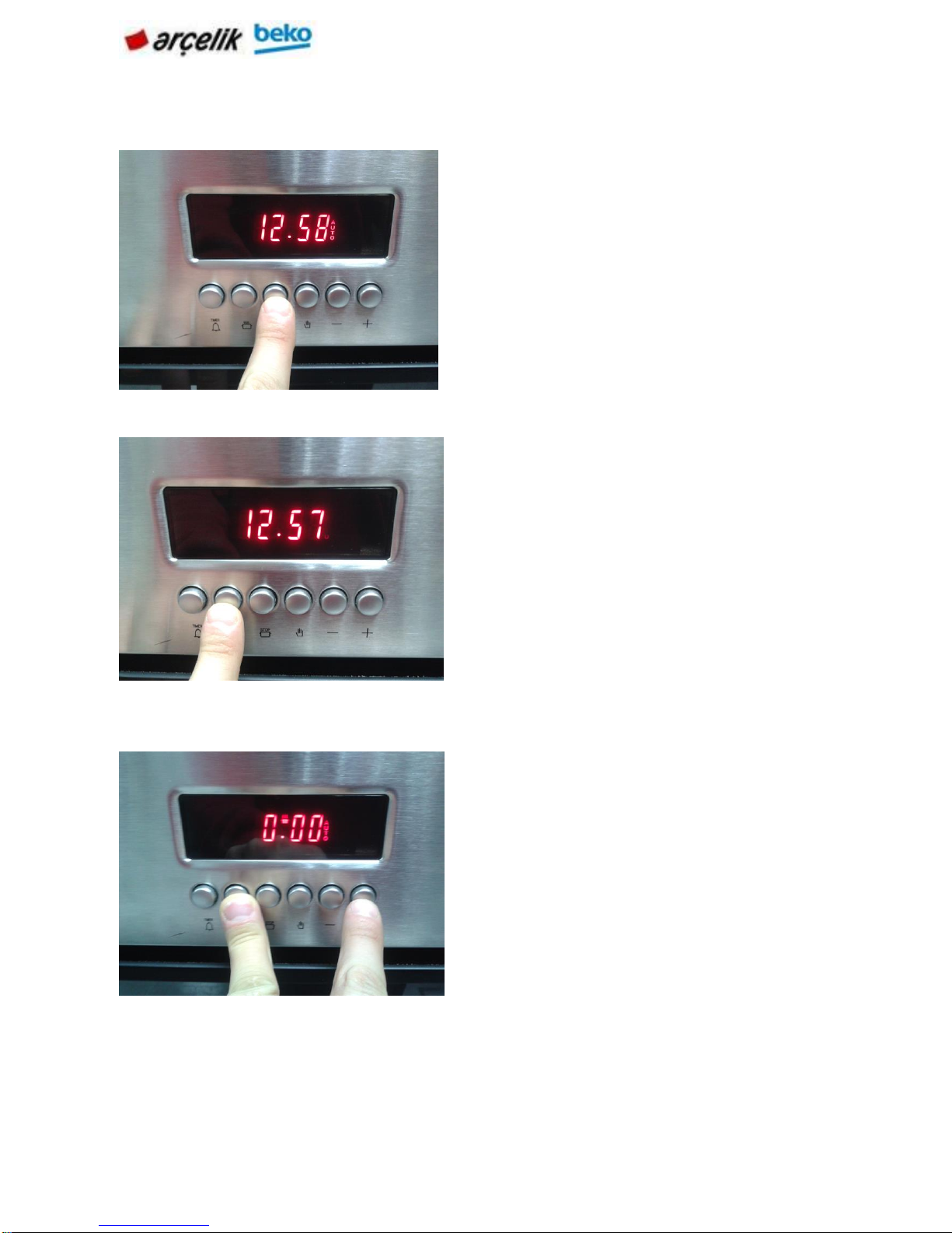
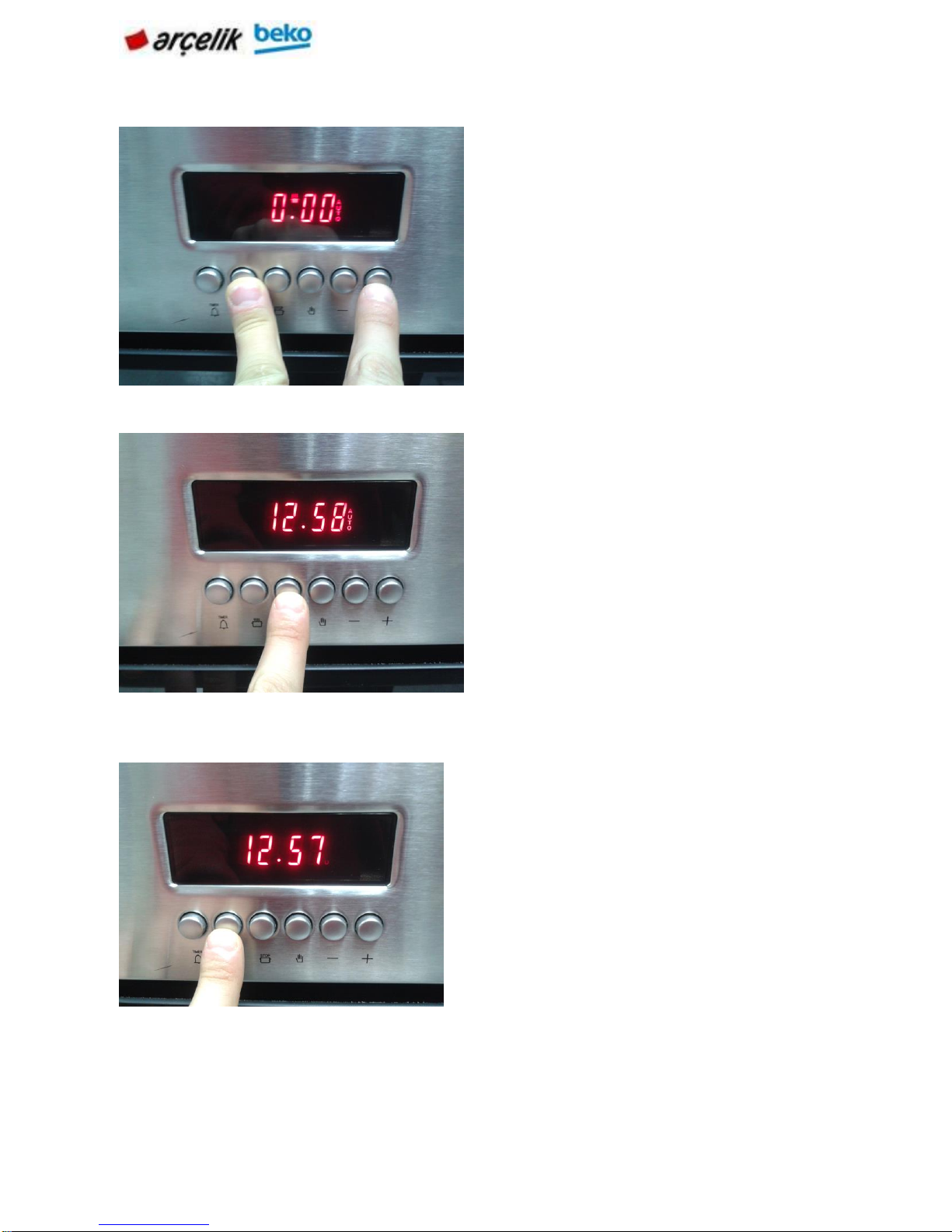
. If you keep the key pressed, the minutes will increase and reset faster.
Release the key (3).
Keep the key (2) pressed.
Press (5) or (6) keys to set the cooking
time. Press the key with short
intervals to increase or reset the
time with increments of 1 minute
Page 20
20 | EN
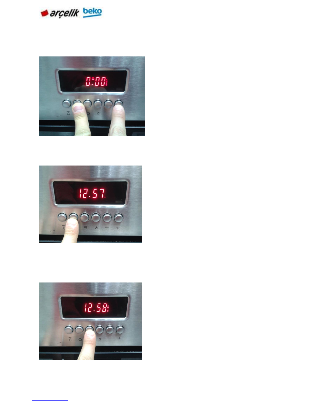
Select operation mode and temperature.
The oven will be heated up to the preset temperature and will maintain this temperature
until the end of the cooking time you selected. The cooking symbol appears on the display
during the cooking process.
Release the key (2).
Press the key (3) when cooking
completes and the alarm sounds.
Page 21
21 | EN
Turn off the oven with the Temperature knob and/or Function knob.
Switch on semi-automatic operation
In this operation mode, oven starts cooking once you enter the cooking time.
Press the key (4). AUTO symbol
on the display disappears.
Keep the key (2) pressed.
Page 22
22 | EN
Press (5) or (6) keys to set the
cooking time. Press the key with
short intervals to increase or
reset the time with increments of
1 minute. If you keep the key
pressed, the minutes will
increase and reset faster.
» AUTO symbol appears on the
display.
Release the key (2).
Page 23
23 | EN
Press the key with short intervals to increase or reset the time with increments of 1 minute.
If you keep the key pressed, the minutes will increase and reset faster.
The oven will be heated up to the preset temperature and will maintain this temperature
until the end of the cooking time you selected. The cooking symbol appears on the display
during the cooking process.
Press (5) or (6) keys to set the cooking
time.
» AUTO symbol appears on the display.
Release the key (2). Put your
dish into the oven.
Press the key (3) when cooking
completes and the alarm sounds.
Page 24
24 | EN
The cooking symbol appears on the display during the cooking process.
Turn off the oven with the Temperature knob and/or Function knob.
Press the key (4). AUTO symbol
on the display disappears.
Keep the key (2) pressed.
Page 25
25 | EN
Using the clock as an alarm
You can use the clock of the product for any warning or reminder apart from the cooking
programme.
The alarm clock has no influence on the functions of the oven. It is only used as a warning.
For example, this is useful when you want to turn food in the oven at a certain point of time.
Alarm clock will give a signal once the time you set is over.
Keep the key (5) pressed until
"0.00" appears on the display as
the remaining cooking time.
Release the key (2).
Press the key (4).
Page 26
26 | EN
Keys:
1
Alarm key
2
Cooking time
3
End of cooking time
4
Unscheduled cooking
Time adjustment keys:
5
Minus key
6
Plus key
Setting the alarm clock
Alarm clock symbol appears on the display.
Keep Alarm key (1) pressed.
Press (5) and (6) keys to determine
how long after the alarm will sound.
Press the key repeatedly to increase or
reset the time with increments of 1
minute. If you keep the key pressed,
the minutes will increase and reset
faster.
Page 27
27 | EN
Turning off the alarm
If you want to cancel the alarm
6.3.2 Adora clock products
1
Main oven function knob
2
Main oven thermostat knob
3
Digital timer
4
Top oven function knob
5
Top oven thermostat knob
6
Thermostat lamp for main oven
7
Thermostat lamp for top oven
Press End of Cooking Time key
(3) when the alarm sounds.
Keep Alarm key (1) pressed.
Keep the key (5) pressed until
"0.00" appears on the display as the
remaining time.
Release Alarm key (1)
Alarm clock symbol on the display
disappears.
Page 28
28 | EN
1
Program key
2
Cooking time
3
End of cooking time
4
Alarm symbol
5
Minus key
6
Plus key
7
Screen brightness setting
8
Alarm volume
9
Current time
10
Keylock
11
Adjustment key
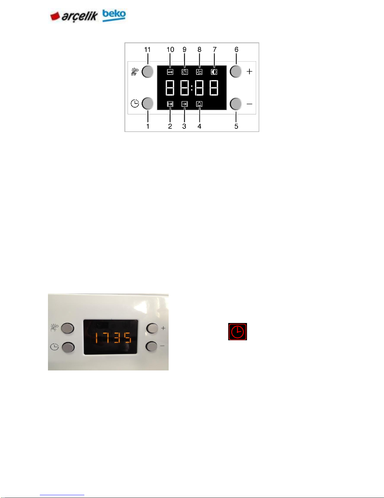
NOTE: Before you can use the oven, the time must be set. If the time is not set, oven will
not operate. While making any adjustment, related symbols on the clock will flash.
Time setting
NOTE: If the current time is not set, time setting will start increasing/moving up from 12:00.
NOTE: Current time settings are cancelled in case of power failure. It needs to be
readjusted.
Press „–“ or „+“ (5/6) keys to set the time
after the oven in energized for the first time.
Clock symbol ' ' will be displayed to
indicate that the current time has not been set.
This symbol will disappear once the time is set.
Page 29
29 | EN
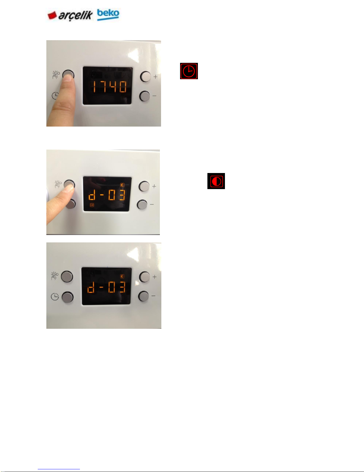
Changing screen brightness adjustment
Using the oven clock
NOTE: Maximum time that can be set for end of cooking is 5 hours 59 minutes.
Program will be cancelled in case of power failure. You must reprogram the oven.
NOTE: While making any adjustments, related symbols will flash on the display
NOTE: If no cooking setting is made, time of the day cannot be set.
Press (11) key to activate current time symbol '
'. Press „–“ or „+“ (5/6) keys to set the
current time.
Press (11) key to activate screen brightness
symbol ' ' for screen brightness
adjustment. Press „–“ or „+“ (5/6) keys to
set the current time.
Selected brightness level will appear as d
01, d-02 or d-03 on the display.
Page 30
30 | EN
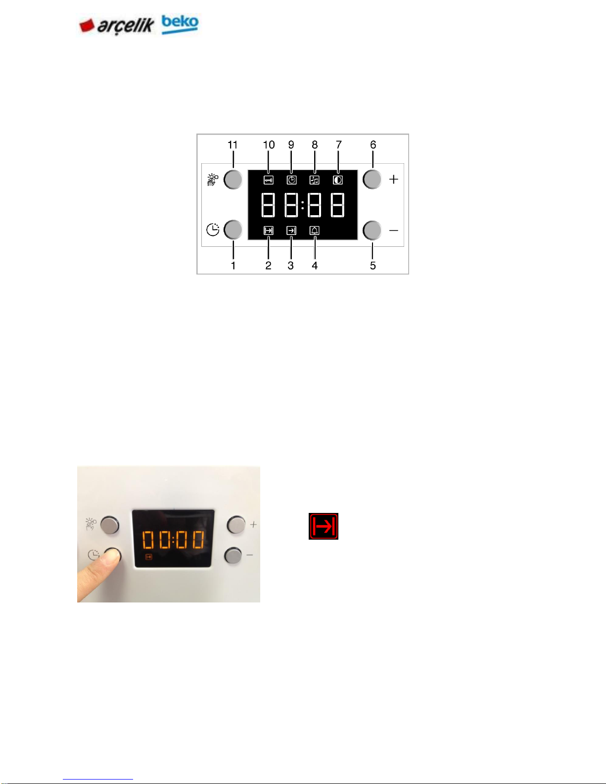
Cooking by specifying the cooking time:
You can set the oven so that it will stop at the end of the specified time by setting the
cooking time on the clock.
1
Program key
2
Cooking time
3
End of cooking time
4
Alarm symbol
5
Minus key
6
Plus key
7
Screen brightness setting
8
Alarm volume
9
Current time
10
Keylock
11
Adjustment key
If you want to set the end of cooking time to a later time:
After setting the cooking time on the clock, you can set the end of cooking time to a later
time.
To adjust the cooking time, Press Program key
(1) and activate the Cooking Time symbol (2)
.Press '–' / '+' (5/6) keys to set the
cooking time. Once the Cooking Time is set,
Cooking symbol will be displayed continuously.
Page 31

31 | EN
» Cooking Time symbol remains lit (displayed continuously) after setting the cooking time.
NOTE: Oven timer automatically calculates the startup time for cooking by using the end of
cooking time and the cooking period you have set. Selected operation mode is activated
when the startup time of cooking has come and the oven is heated up to the set
temperature. It maintains this temperature until the end of cooking time.
To adjust the cooking time, press Program key
(1) and activate the Cooking Time symbol (2)
.Adjust the cooking time with Minus (5)
and Plus (6) keys.
To set the End of Cooking Time, Press
Program key (1) and activate the Cooking
Time symbol (3) . Press - (5) and + (6)
keys to set the end of cooking time.
Once the End of Cooking Time is set, End of
Cooking symbol and Cooking symbol will be
displayed continuously. The End of Cooking
Time symbol (3) will disappear as soon
as the cooking starts. Put your dish into the
Page 32

32 | EN
NOTE: If you mute the alarm by pressing any key, the oven will restart operating.
If you press any button at the end of the alarm period, the oven will restart operating.
Using the keylock
Activating the keylock
You can prevent oven from being used by activating the Keylock function.
1
Program key
2
Cooking time
3
End of cooking time
4
Alarm symbol
5
Minus key
6
Plus key
7
Screen brightness setting
8
Alarm volume
9
Current time
10
Keylock
11
Adjustment key
After the cooking process is completed, "End"
appears on the displayed and the alarm will
sound. Alarm signal will sound for 2 minutes.
To stop the alarm signal, just press any key.
Alarm will be silenced and current time will be
displayed.
Page 33

33 | EN
Deactivating the keylock
Press the key (11) to activate Keylock symbol
(10) . "OFF" will appear on the display.
Press '+' key (6) to activate the keylock.. Once
the keylock is activated, "On" appears on the
display and the Keylock symbol (10)
remains lit.
When the Keylock function is activated, control
panel buttons except for the key (11) cannot
be used.
Press Adjustment key (11) to activate Keylock
symbol (10) . On" will appear on the
display.
Page 34

34 | EN
Using the clock as an alarm
You can use the clock of the product for any warning or reminder apart from the cooking
programme.
The alarm clock has no influence on the functions of the oven. It is only used as a warning.
For example, this is useful when you want to turn food in the oven at a certain point of time.
Alarm clock will give a signal once the time you set is over.
1
Program key
2
Cooking time
3
End of cooking time
4
Alarm symbol
5
Minus key
6
Plus key
7
Screen brightness setting
8
Alarm volume
9
Current time
10
Keylock
11
Adjustment key
Press '–' (5) to deactivate the keylock. OFF"
will be displayed once the keylock is
deactivated.
Page 35

35 | EN
Maximum alarm time can be 23 hours and 59 minutes.
NOTE: Alarm time will be displayed. If the alarm time and cooking time are set
concurrently, shortest time will be displayed.
Press Program key (1) to activate the alarm
time symbol (4).
Adjust the alarm time using
„+“ /„–“
(5/6) keys.
Alarm symbol will remain lit and the alarm time
will appear on the display once the alarm time
is set. At the end of the alarm time, Alarm Time
symbol (4) will start flashing and the
alarm signal is heard. To stop the alarm, just
press any key.
To reset the alarm time, press Program key (1)
to activate the alarm time symbol (4) .
Press and hold the '–' (5) key until "00:00" is
displayed.
Page 36

36 | EN
Changing alarm tone
Press Setting key (11) to activate the Alarm
Tone symbol (8) .
Adjust the desired tone using
„+“ /„–“
(5/6)
keys. Selected alarm tone will appear as "b-
01", "b-02" or "b-03" on the display.
Page 37

37 | EN
7.BY PRODUCTS/PRODUCTS LABELS USED
7.1 Accessories
Oven Tray
Cake Tray
Wire Grid
Page 38

38 | EN
7.2 Tags and Descriptions used in the product
7.2.1 Type the label
Given information on the product nameplate label on the product gas.
Sticker on the location;
According to the type of product, or the product can be seen in the front door or the rear
wall of the lower lid is opened.
Page 39

39 | EN
7.2.2 Barcode Label
Product bar code label of the product produced in the country, defining the characteristics
of the brand and model, defined lines and spaces according to the rules of international
label.
Barcode label location;
Product packaging is pasted on cardboard.
7.3.3 Energy Label
Product energy label product energy class, the label shows the volume of the product.
Page 40

40 | EN
Energy Label lacatıon;
Energy label products are in a group of periodicals.
Page 41

41 | EN
8. GENERAL WORKING PRINCIPLE
Mechanical control circuit used in the mechanical clock-controlled oven (Module) control of
the oven function, showing the mechanical formats, such as furnace uptime, choose food
from the cooking guide, cooking demonstration of recipes, automatic cooking made from
the cooking guide, showing the cooking time, the timer (set the time counting backwards ,
making a sound when time runs out) and gives the internal temperature of the oven control
facilities.
The furnace consists of the following combined and features.
- Depending on the temperature inside the oven (120 ° C ± 20 ° C (1st stage), 300 ° C ± 20
° C (2nd level there are only pyro oven), between the cooling fan control.
- The internal temperature of the furnace can be adjusted between 40 ° C to 280 ° C (± 5 °
C accuracy, ± 10 ° C accuracy from 250-280C)
- Tim (warning time) can be set between 23 hours and 59 minutes to 1 minute.
- The cooking time can be set from 1 minute to 5 hours and 59 minutes.
-Select the endofthecooking time memories
-1100 / 2200WHealth grill resistance
-1800Whealthturbo resistance
-Healthupperovenheating 1100W
-Lower ovenheating1200W health
-22Wness Fan Motor
-The rotisserie function feature (works on the grill function.) (Optional)
Although .Fır any wrong operation is protected by a bi-metal type thermal breaker. Pyro
ovens Bi-metal type in an external furnace is on the left rear upper side of the chassis and
the operating temperature of the thermal breaker oven to 250 ° C. When he came inside the
furnace to a temperature of 350-400 ° C is separated from the phase conductor feeding **.
* Look Out !!!!! The furnace consists of a situation gone wrong on the furnace when thermal
cutting horse. (Such as the operation of the oven temperature sensor) should resolve the
situation bulunarak error before forming replaced.
The cooling fan is connected to the temperature inside the oven (120 ° C ± 20 ° C (1st
stage), 300 ° C ± 20 ° C (2nd level there are only pyro oven), between engaged and ground
inside until it fell to about 160 ° C continues to work. a time to throw heat on the cooling
engine is turned off, even after baking oven control circuit will continue to further study.
Page 42

42 | EN
9. LIST OF COMPONENTS / COMPONENT WORKING PRINCIPLE
9.1 Technical specifications of the components;
Grid Resistance
Oven Heatıng
Clemens
Turbo Motor
Turbo Motor
Thermal circuit breaker
Grid resistance is controlled by the
control button under the commutator.
Oven heating is controlled by the control
button under the commutator. It is located
between chasis and metal sheet of bottom.
Turbo motor is used in multifunction and
turbo motor. It works alone in defrost
mode. When turbo motor works with
resistance, heat spreads homogenously
Thermal circuit breaker is used to cut the power
when the heat of chasis increase so much. It
works in dangerous situation, not normal
condition
Page 43

43 | EN
Turbo Heater
Bi Metal
Turbo heater is used in multifunction and turbo
ovens. It is located in inner back wall of chasis.
When thermal circuit breaker does not work, bi
metal works and cuts the power. It Works
dangerous situation, not normal situation.
Page 44

44 | EN
10. FAULT FLOW / FAULT FINDING DIAGRAMS
10.1.Resistance Faults
10.1.1 Resistance does not work;the food is not cooked
Page 45

45 | EN
10.2 Lamp Fault
10.2.1 Furnace is working but the oven does not illuminate
Page 46

46 | EN
10.2.2 Oven does not work,oven lamp does not light,
Page 47

47 | EN
10.3 Termostat Fault
10.3.1 Furnace runs continuosly,the thermostat is not tripped.
Page 48

48 | EN
10.4 Therminal Fault
10.4.1There is no power from the terminal does not diffuse into the electric furnace
Page 49

49 | EN
10.4.2 When the fuse blows the oven is plugged into the Wall socket.
Page 50

50 | EN
11.COMPONENTS CONTROL
Current and power drawn by components on the product with the instrument called a
multimeter measured.
For the measurement of resistance Turbo example;
The current drawn by the components on
the product and the power is measured
with a multimeter name given instrument.
Multimeter to measure resistance is
brought into position to measure the
resistance of the resistor Turbo.
Resistance cables removed. Probes of a
measuring instrument (end) are allowed
to touch the terminals of the coil.
Page 51

51 | EN
The work of the look of a resistance
value in the multimeter display shows
that in the case.
a resistance value in a secure, avometer
resistance is seen. resistance value
does not appear damaged.
Page 52

52 | EN
12. COMPONENT ASSEMBLY / DISASSEMBLY BE USED IN EQUIPMENT
Screwdrivers
Needlenose
Nippers
Page 53

53 | EN
13.COMPONENT ASSEMBLY / DİSASSEMBLY
NOTE: The following components disassembly operations are related below. For
component installations apply this operations in reverse order.
13.1 Replacement of the knob
Pull knob to yourself to remove. Push the new knob against the control panel. Rounded
sufoces on the knobs shaft and commutators shaft must overlap.
13.2 Replacement of the upper cover sheet
Unscrew 10 screws placed on the upper cover sheet. Pull the tree sheet to wards the rear ot
the oven and lift to remove.
Page 54

54 | TR
13.3 Replacement of the control panel
Unscrew two screws mounted on both right and left side of the panel.
Page 55

55 | EN
Lit the contro panel until pins become free form the housing.Pull the control panel by taking
care of cables.Pull the cable sockets.Away form the panel.
Page 56

56 | EN
13.4 Replacement of the front door
Open the oven door.
As shown in the picture,pull down the hinge clips on both sides ot the oven door.
Page 57

57 | EN
.Position the door halt open as shown. Remove the oven door by pulling it away trom the oven
as it is in the halt open position.
Important: Don't forget to close the hinge clips when reassembling the door.Other wise,the
door can't be closed.
13.5 Replacement the front door hinge
Remove the front cover with the screws with a screwdriver after removal of the side of the
hinges.
Page 58

58 | EN
After removing the screws on the hinges to pull the empty slot and change with a new
hinge.
13.6 Replacement of the removable glass cover 3
Remove the top decor, located on the lid first.
Pull yourself to remove the front door inner glass.
Page 59

59 | EN
Get in the middle of the glass remaining in pulling yourself.
After removing the screws pull as seen in the picture below.
Page 60

60 | EN
13.7 Replacement of the removable glass cover 2
Before replacement ot the oven door according to instructions in user manuel.
Remove door inner glass by apparatus tor removing the inner glass.Insert apparatus to signet
gap on the glass and move the glass up.
Page 61

61 | EN
Page 62

62 | EN
Before remove the bottom sheet metal unscrew the screws both sides of the bottom sheet
metal.
Unscrews placed bottom in the oven door.
Page 63

63 | EN
Remove plastic parts (protiles) figure as shown.
Ventilation decors can be changed by apparatus for removing the inner glass.
Page 64

64 | EN
Glass fixing locks can be replaced.
Page 65

65 | EN
13.8 Replacement of the removable glass cover 4
Remove of the plastic part mounted upper side of the oven door by pulling yourself.
Lift in mast glass up then remove then glass by pulling in direction as shown in the figure.
Repair this operation to remove the second and third inner glass.
Page 66

66 | EN
Important:
It is important in mounting all inner glasses to position the bottom corners ot
glasses in to the bottom plastic housings properly.
Page 67

67 | EN
Screw glass carrying plastic to locking springs. Fix,group to door left / right profiles.
Bands are sticked to in mast door metal sheet on both sides of the door profiles.
Page 68

68 | EN
13.9 Replacement of the handle
First disassemble the oven door. Use an alien key sited 2 to remove the handle screws placed
two sides ot the handle.
Remove the handle by pulling away trom the oven door.
Page 69

69 | EN
Cover and insert the remaining 2 screws holding the screwdriver handle with the help of the
clipboard.
13.10 Replacement of the comutators
Firstly,remove the knobs and disassemble the control panel. Unplug the electrical connection
plugs ot the comutator to be replaced.
Unbend the pins ot control panel.Demount the pin ot comutator plasic placed in to hole on the
control panel.Turn the comutator plastic in clockwise direction to the plastic trom demount.
Page 70

70 | EN
13.11 Replacement of the oven thermostat
First remove the thermostat knob and disassamble the conrol panel.Unbend the panel pin and
demount the thermostat plastic pin trom the control panel.
Turn commutator plastic clockwise direction to remove the group trom the panel.
Page 71

71 | EN
13.12 Replacement of the thermostat bulb
Thermostat bulb is placed on the right top ot the rear wall ot the cavity To reach thermostat
bulb,upper and rear cover sheets should be demounted unscrew the screw ot bulb support
sheet.
Pull the sheet away trom the cavity.
Page 72

72 | EN
Pull the bulb away trom the support sheet.Replace the bulb with new one and do operations ot
demounting in reverse order to assemble the new bulb.
View ot the bulbin oven cavity can be seen in the picture.
Page 73

73 | EN
13.13 Replacement of the bi-metal thermostat
First remove the thermostat knob and disassambie the control panel.Unbend the panel pin and
demount the thermostat plastic pin trom the control panel.Turn comutator plastic clockwise
direction to remove the group trom the panel.
13.14 Replacement of the engine cooling
To reach the cooling motor upper cover sheet should be demounted.
Page 74

74 | EN
Cooling up tor is placed on the upper wall ot oven cavity Turn the cooling motor and support
sheet group clock wise direction to demount.
13.15 Replacement of the ventilation plate
First replace the upper cover sheet. Unscrew 2 screws which hold the ventilation sheet
metal,are placed the cavity inner ceilling.
Page 75

75 | EN
Ventilation sheet metal could be removed by pulling it as shown in the figure.
13.16 Replacement of the ventilation thermostat
Firstly remove oven cover upper sheet metal. Ventilation thermostat is tixed to ventilation hole
by two screws.
Page 76

76 | EN
Change / remove ventilation thermostat by unscrew the screws.
Page 77

77 | EN
13.17 Replacement of the rear cover sheet
Unscrew 8 screws lased for mounting the rear cover sheet and remove the sheet.
Oven back wall will be side opening position.
This rear back wall can be dismount from notched.
Page 78

78 | EN
13.18 Replacement of the side walls
Unscrew 7 screws and remove the free side wall.
Dismount the side wall in order to remove the front side profiles. Afterwords, unscrews the three
screws replace by the new one.
Page 79

79 | EN
13.19 Replacement of the bottom plate
Unscrew ten screws on the oven floor sheet.
Remove the oven floor sheet as shown in the figure.
Page 80

80 | EN
13.20 Replacement of the switch
Top wall should be removed in order to diassembie the switch. Unscrew the screw which
hold switch to side wall.
Afterwords,displaced the switch from oven side wall.
Page 81

81 | EN
Pull the switch and the change by the new one.
Page 82

82 | EN
13.21 Replacement of cataliytic side walls
Switch
Page 83

83 | EN
Firstly, remove the wire shelf that are in front of the catalytic side walls. Then screw off wire
rack screws.
13.22 Replacement of top heating element
Dismount rear and top cover sheets.
Dismount electrical connections.
Page 84

84 | EN
Screw off 2 screws.
Open the front cover and ground grid resistance 2 Remove the screw that connects to the
wall.
Page 85

85 | EN
Get off the grid’s idled resistance from the plate. Then, insert new resistance’s terminales
by following electrical schematic, and close the back wall.
13.23 Replacement of the bottom heating element
Fisrt dismount the rear cover sheet.
Dismount electrical connections.
Page 86

86 | EN
Resistor connection Unscrew the screws with a screwdriver. Pull the heaters towards
yourself to dismount.
13.24 Replacement of the ring heater
Firstly,remove the oven top and back wall. Disconnect the wiring for ring heater.
Page 87

87 | EN
Remove the fan cover sheet by unscrewing the screws. Afterwords,unsscrew the two screws
that fixed the ring heater to cavity.
Page 88

88 | EN
Take the ring heater from inside cavity.Connect the wire to terminal according to wiring
diagram and close in back wall.
13.25 Replacement of the seal oven
Open the oven door. Remove the seal from hole on the cavity and replace with new one.
Page 89

89 | EN
13.26 Replacement of the turbo motor
Firstly,remove the oven top wall,back wall and tan cover sheet. Disconnect the wire.
Page 90

90 | EN
Turbo fan Unscrew the nut and fan with the help of forceps taken.
Turbo engine that connects to the chassis by removing 3 screws, replace the turbo engine.
Then the electrical terminals according to the scheme of the new turbo engine and rear
walls turn off your jewelry.
Page 91

91 | EN
13.27 Replacement of the terminal box
Firstly,remove the back wall.
Open the terminal cover.
Page 92

92 | EN
Terminal that connects to the rear wall and right in the box on the left (marked in the
picture) Unscrew the screws with a screwdriver. Remove the cables in the back wall of the
terminal block.
Terminals and the cable from the wall and replace it with a new scheme by removing the
electrical connection structure according to your.
.
Page 93

93 | EN
13.28 Replacing the runners
Located in the side walls of the furnace to get the wire rack wire rack wire rack bolts from
the housing and replace it with a new wire rack.
13.29 Replacing the oven lamp
Located in the oven to duy lamb + glass group just to change the lamp Unscrew the glass.
Located in the oven replace it with a new lamp.
Page 94

94 | EN
Hear the oven light bulb with lamp + glass behind the bakery to change your senses in the
upper right side of your nails unscrew the rescue.
13.30 Replacement of the oven square lamp
Located on the side walls within the chassis frame, freeing you from the lamp, remove the
nail and replace it with a new one.
Page 95

95 | EN
13.31 Replacement of the signal lamp
Firstly remove the burner plate.
Depends on the signal lamp socket, plug socket, remove the signal lamp behind the
dashboard.
Page 96

96 | TR
Sticking Pull the plug and replace the signal lamp
13.32 Replacement of the Glass Wool
For this operation must remove the first side walls and the rear housing
Disconnect the frame wire around the wire wrapped with glass wool.
Glass wool loose change with a new one.
Page 97

97 | EN
Page 98

98 | EN
13.33 Replacement of the 6 button hours
This process must be removed before the control panel.
Pull the cables according to the time taken.
Unscrew the panel under 2 hours support plate screws. Take the clock support sheet.
Remove the cover tabs depending on the hours of pushing over time with the help of the
screwdeiver.
Page 99

99 | EN
13.34 Replacement of the adora timer
Unscrew the top of the wall to change the time.
Remove the cable groups on the hour.
Page 100

100 | EN
Remove the upper screw screwdriver to remove the clock.
Remove the screw under the hour.
 Loading...