

Page 1
5.8 GHz Wireless AV Sender
Instruction Manual
LAVSEN10
Page 2

Page 3

Contents
Unpacking ��������������������������������������������������������������������������������� 4
Product Overview ��������������������������������������������������������������������� 5
Transmitter �������������������������������������������������������������������������������������������������������������5
Receiver �������������������������������������������������������������������������������������������������������������������5
IR Remote Extender ���������������������������������������������������������������������������������������������6
Getting the Best Reception ������������������������������������������������������������������������������7
Setting Up your AV Sender ������������������������������������������������������ 8
Connecting the Receiver �����������������������������������������������������������������������������������8
IR Remote Extender ���������������������������������������������������������������������������������������������8
Connecting the Transmitter �������������������������������������������������������������������������� 10
Hints and Tips ������������������������������������������������������������������������� 13
Specifications �������������������������������������������������������������������������� 14
Transmitter ���������������������������������������������������������������������������������������������������������� 14
Receiver ���������������������������������������������������������������������������������������������������������������� 15
Safety Warnings ���������������������������������������������������������������������� 16
Page 4
Thank you for purchasing your new Logik 5�8 GHz Wirless
AV Sender�
We recommend that you spend some time to read this manual in
order to fully understand how to install and operate it correctly�
Read all the safety warnings carefully before use and keep this
manual for future reference�
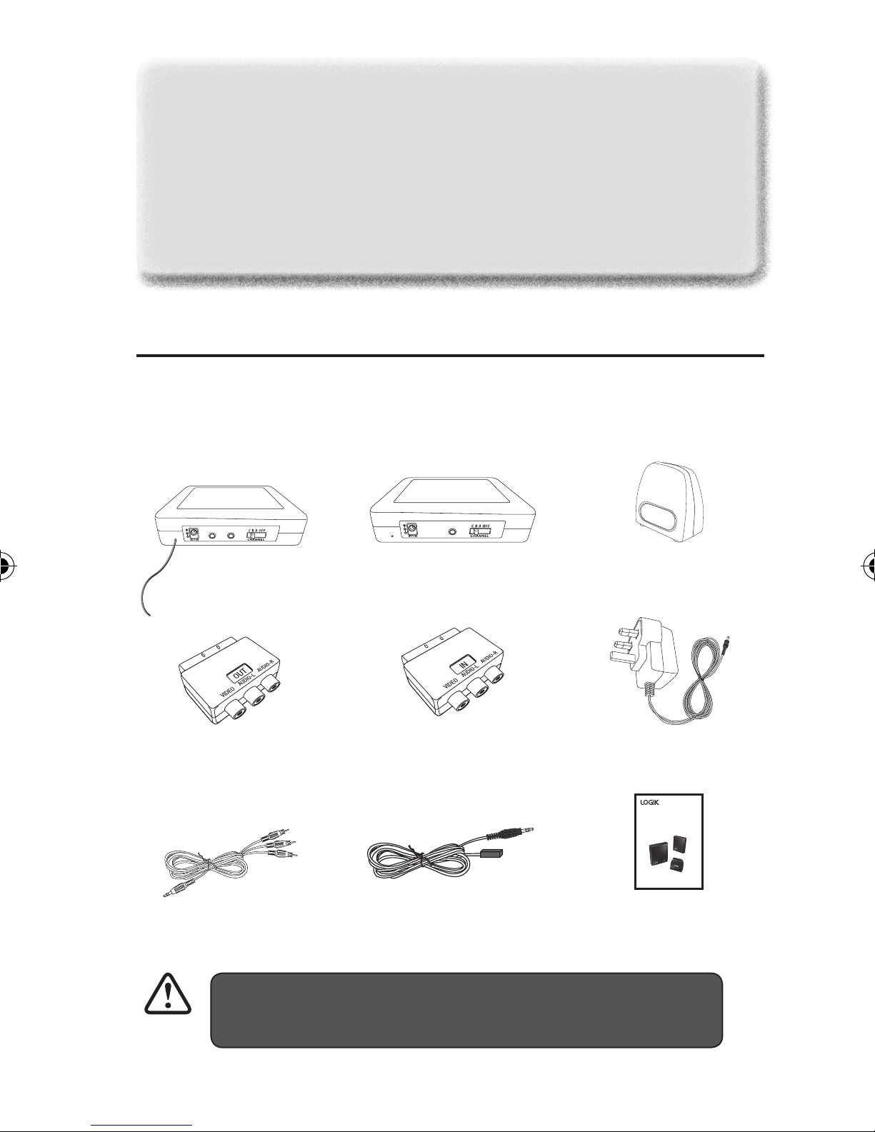
Unpacking
Remove all packaging from the unit� Retain the packaging� If you
dispose of it please do so according to local regulations�
The following items are included:
A/V INIR EX T.
Transmitter x 1
(P�N� VT58LOW=175U)
SCART OUT RCA Adapter
(for transmitter) x 1
(P�N� 149=00000114)
3�5mm to RCA cables x 2
(P�N� 363=00000164)
A/V O UT
Receiver x 1
(P�N� VR58LOW=175U)
SCART IN RCA Adapter
(for receiver) x 1
(P�N� 149=00000113)
IR Remote extender cable x 1
(P�N� 851100=10121)
IR Remote extender x 1
(P�N� ST18IR=175U)
Power adapters x 2
(P�N� 307001=10206)
5.8 GHz Wirl ess AV Sender
Instruction Manual
LAVSEN10
Instruction Manual
(P�N� 033000=15509-V2)
If items are missing or damaged, please contact
Partmaster (UK only)� Tel: 0844 800 3456 for assistance�
GB-4
Page 5
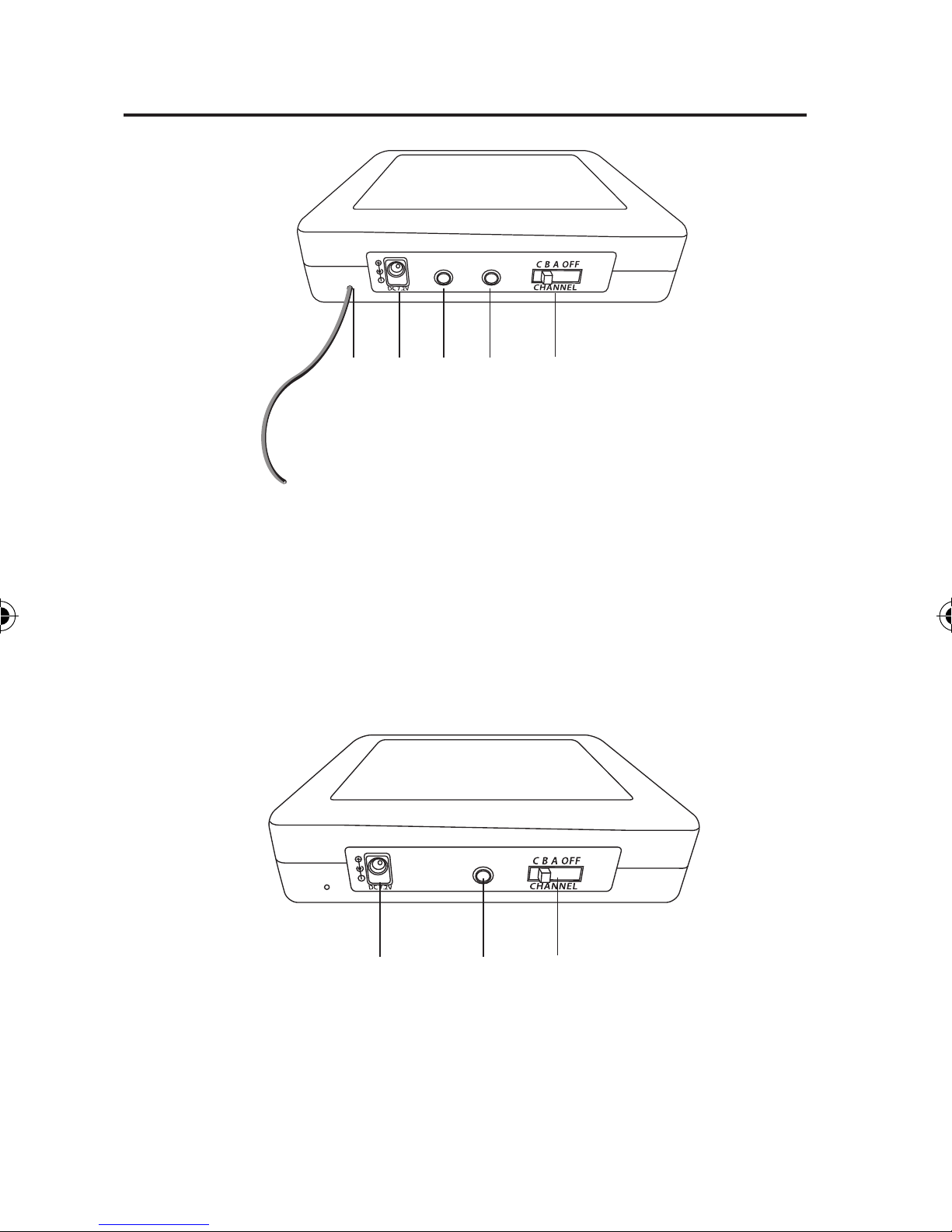
Product Overview
Transmitter
1 2 3 4 5
1� Transmitter aerial
2� Power adapter socket
3� IR remote extender socket
A/V INIR EXT.
Receiver
4� A/V IN socket
5� Channel select / OFF switch
A/ V O UT
1 2 3
1� Power adapter socket
2� A/V OUT socket
3� Channel select / OFF switch
GB-5
Page 6
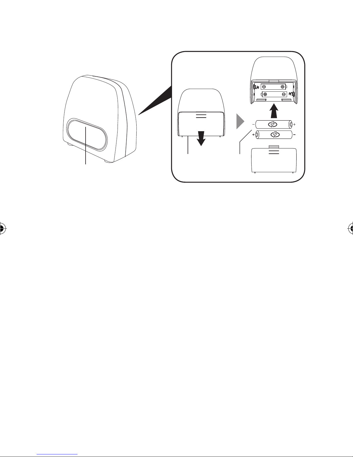
IR Remote Extender
1
rear side
2 3
1� Remote control sensor
2� Battery compartment
3� 1�5V AAA Batteries
Handling the Batteries
• Improper or incorrect use of batteries may cause corrosion or
battery leakage, which could cause personal injury or damage to
property�
• Install the batteries correctly by following the polarity (+ and –)
indications in the battery compartment�
• Use only the types of the batteries which are indicated in this
manual�
• Do not install new batteries with used ones and do not mix
different types of batteries�
• Do not dispose of the used batteries as domestic waste� Dispose of
them in accordance with local regulations�
GB-6
Page 7

Getting the Best Reception
1� This system is a wireless communication product� The
installation location should have no blockage to avoid
interfering with transmission and reception� The distance
between the transmitter and receiver should be greater than 5
metres to receive the best signal�
2� The transmitter and receiver in this system are for indoor use
only�
3� After installation, if the picture is not clear or the picture is
rolling, then the transmitter location may have exceeded the
effective transmission distance� Please move or change the
Transmitter location�
4� To reduce interference the AC adapter, which comes with this
system, should not be plugged into the same mains socket as
other appliances�
GB-7
Page 8

Setting Up your AV Sender
Connecting The Receiver (connect to 2
nd
TV (e�g� bedroom or kitchen)
1� Plug the supplies 3�5mm to RCA cable into the A/V OUT socket
on the receiver and then plug into the RCA socket on your TV
located in the receiving room�
*Optional: Alternatively you may use the supplied
SCART IN RCA adapter (Receiver)�
2� Connect one of the supplied power adapters to the power
adapter socket on the receiver and then plug the power adapter
into the mains socket�
IR Remote Extender
3� Open the battery compartment cover� Insert 2 AAA batteries
and then replace the cover�
Please insert the batteries with the correct polarities�
4� Position the remote extender on top / in front of your TV or
any other location in the direct line of sight with your remote
controls� Use an adhesive pad to hold it in place when you are
happy with the position�
GB-8
Page 9

Bedroom
2
Power
Adapter
Receiver
A/V OUT
10
1
3.5mm to
RCA Cable
3.5mm to
RCA Cable
*Optional
VIDEO AUDIO-L AUDIO-R
IN
SCART IN
RCA Adapter
TV
TV
3
IR Remote
Extender
IR Remote Extender
4
Receiver
TV
GB-9
Page 10

Connecting The Transmitter (main viewing room, e�g� sitting room)
5� Plug the supplied 3�5mm to RCA cable into the A/V IN socket on
the transmitter and then plug into the SCART output socket on
your AV source device (e�g� satellite receiver, VCR or DVD player)�
**Optional: Alternatively you may also use the supplied
SCART OUT RCA adapter (Transmitter)�
6� Plug the IR remote extender cable into the IR remote extender
socket on the transmitter�
7� Position the IR remote extender cable in front of the IR sensor
window of your AV source device (e�g� satellite receiver, VCR or
DVD player)�
8� Connect the remaining power adapter to the power adapter
socket on the transmitter and then plug the power adapter into
the mains socket�
9� Both the transmitter and receiver have a Channel Select / OFF
switch� Ensure that the same Channel / OFF switch on both the
transmitter and receiver are set to the same channel A, B, C�
10� Select an appropriate AV channel on the receiving TV� The TV
should now show whatever signal the transmitter is sending
and if the IR remote extender cable is properly positioned, you
will be able to control the AV source by pointing the correct
remote control at the IR remote extender on top / in front of
your TV�
GB-10
Page 11

Transmitter
A/V OUTIR E XT.
Sitting room
9
10
3.5mm to
RCA Cable
7
IR Remote
Extender Cable
5
6
3.5mm to
RCA Cable
8
**Optional
VIDEO AUDIO-L AUDIO-R
OUT
SCART OUT
RCA Adapter
DVD
Player
Satellite / VCR /
DVD Player
Power
Adapter
GB-11
Page 12

Bedroom
IR Remote
Extender
Receiver
Sitting Room
GB-12
DVD Player
Transmitter
Page 13

Hints and Tips
Buzzing noise
when you use the
remote control�
The image of
the video source
disappears from
the TV
The video sources
do not respond to
the remote control
commands
• Slightly change the position of the
receiver or the transmitter until the
buzzing sound stops�
• Sometimes it is not possible to solve the
problem�
• Turn off the auto standby mode of the
video source� Refer to its user manual�
• Follow the instructions to reconnect the
video sources�
• Point the remote control directly at the
receiver�
• Replace the batteries of the remote
controls with new ones�
• Use and position the IR extender�
• The maximum operating distance of the
Interference in the
image on TV
remote control is 5m�
• Slightly change the position of the
receiver or the transmitter�
• Change the wireless channel that is used
for communication�
• The receiver is out of range of the
transmitter�
• The number of walls and cellings in
between the receiver and transmitter is
affecting the signals�
GB-13
Page 14

Specifications
Transmitter
Video Input RCA JACK, 1Vp-p, 75Ω
Audio Input RCA JACK, 1Vp-p, 10KΩ
Transmitter Frequency 5�745 ~ 5�805GHz
Modulation FM (Audio & Video)
Channel Number 3@18MHz/CH�
RF Output Level 10dBm
Clear Line-Of Sight Range Max� 30m
Power Source
IR Emitter Section
Carrier Frequency From remote source
Distance between Emitter & Detect 5 Meters (Min�) 6 Meters (Typ�)
Half Angle ±33°
RF Section
Receiver Frequency 433�92 MHz ±500KHz
230V ~ 50Hz/7�2V , 250mA Adapter
GB-14
Page 15

Receiver
Video Input RCA JACK, 1Vp-p, 75Ω
Audio Input RCA JACK, 1Vp-p, 10KΩ
Transmitter Frequency 5�745 ~ 5�805GHz
Channel Number 3@18MHz/CH�
Power Source
230V ~ 50Hz/7�2V , 250mA Adapter
IR Emitter Section
Carrier Frequency 30K~60KHz
Half Angle ±33°
Receiver Distance 4�5 Meters (Min�) 6 Meters (Typ�)
RF Section
Transmitter Frequency 433�92 MHz ±500KHz
Transmitter Power Level 10dBm
GB-15
Page 16

Safety Warnings
• Read all the instructions carefully before using the unit and keep them for future
reference�
• Retain the manual� If you pass the unit onto a third party make sure to include
this manual�
• Check that the voltage marked on the rating label matches your mains voltage�
Damage
• Please inspect the unit for damage after unpacking�
• Do not continue to operate the unit if you are in any doubt about it working
normally, or if it is damaged in any way - switch o, withdraw the mains adapter
and consult your dealer�
Location of Unit
• The unit must be placed on a at stable surface and not subjected to vibrations�
• Do not place the unit on sloped or unstable surfaces as the unit may fall o or
tip over�
• The mains socket must be located near the unit and should be easily accessible�
• This unit is designed for indoor use only�
Temperature
• Avoid extreme degrees of temperature, either hot or cold� Place the unit well
away from heat sources such as radiators or gas/electric res�
• Do not expose the battery to direct sunlight or sources of excessive heat�
Naked Flames
• Never place any type of candle or naked ame on the top of or near the unit�
Moisture
• To reduce the risk of re, electric shock or product damage, do not expose this
unit to rain, moisture, dripping or splashing� No objects lled with liquids, such
as vases, should be placed on the unit�
• If you spill any liquid into the unit, it can cause serious damage� Switch it o at
the mains immediately� Withdraw the mains plug and consult your dealer�
Ventilation
• To prevent the risk of electric shock or re hazard due to overheating, ensure
that curtains and other materials do not obstruct the ventilation vents�
• Do not install or place this unit in a bookcase, built-in cabinet or in another
conned space� Ensure the unit is well ventilated�
Safety
• Always disconnect the unit from the mains supply before connecting/
disconnecting other devices or moving the unit�
GB-16
Page 17

• Unplug the unit from the mains socket during a lightning storm�
• In the interests of safety and to avoid unnecessary energy consumption,
never leave the unit switched on while unattended for long periods of time,
e�g� overnight, while on holiday or while out of the house� Switch it o and
disconnect the mains adapter from the mains socket�
Mains Adapter Cable
• Make sure the unit or unit stand is not resting on top of the mains adapter cable,
as the weight of the unit may damage the mains adapter and create a safety
hazard�
Interference
• Do not place the unit on or near appliances which may cause electromagnetic
interference� If you do, it may adversely aect the working of the unit, and cause
a distorted sound�
Supervision
• Children should be supervised to ensure that they do not play with the unit�
• Never let anyone especially children push anything into the holes, slots or any
other openings in the case - this could result in a fatal electric shock�
CAUTION
RISK OF ELECTRIC SHOCK
DO NOT OPEN
The lightning ash with arrowhead symbol, within an equilateral triangle,
is intended to alert the user to the presence of uninsulated “dangerous
voltage” within the unit’s enclosure that may be of sucient magnitude to
constitute a risk of electric shock�
The exclamation point within an equilateral triangle is intended to alert the
user to the presence of important operating and maintenance (servicing)
instructions in the manual accompanying the unit�
Service
• To reduce the risk of electric shock, do not remove screws� The unit does not
contain any user-serviceable parts� Please leave all maintenance work to
qualied personnel�
• Do not open any xed covers as this may expose dangerous voltages�
Maintenance
• Ensure to unplug the unit from the mains socket before cleaning�
• Do not use any type of abrasive pad or abrasive cleaning solutions as these may
damage the unit’s surface�
• Do not use liquids to clean the unit�
GB-17
Page 18

Page 19

Page 20

If you require a replacement for any of the items listed below, please quote their
corresponding part numbers:
Replacement Part Part Number
Transmitter VT58LOW=175U
Receiver VR58LOW=175U
IR Remote Extender ST18IR=175U
SCART OUT RAC Adapter (for transmitter) 149=00000114
SCART IN RAC Adapter (for receiver) 149=00000113
Power Adapter 307001=10206
3�5mm to RCA cables 363=00000164
IR Remote extender cable 851100=10121
DSG International Sourcing declares that the unit comply with the essential requirements
and other relevant provisions of Directive 1999/5/EC�
Visit Partmaster�co�uk today for the easiest way to buy
electrical spares and accessories� With over 1 million
spares and accessories available we can deliver direct to
your door the very next day�
Visit www�partmaster�co�uk or call 0844 800 3456 (UK customers only) Calls charged at
National Rate�
This symbol on the product or in the instructions means that your electrical
and electronic equipment should be disposed at the end of its life separately
from your household waste� There are separate collection systems for recycling
in the EU�
For more information, please contact the local authority or your retailer where
you purchased the product�
DSGRetailLtd.•MaylandsAvenue•HemelHempstead
Herts•HP27TG•England
(P�N� 033000=15509-V2)
 Loading...