

CaretakerSentry Quick Install Guide
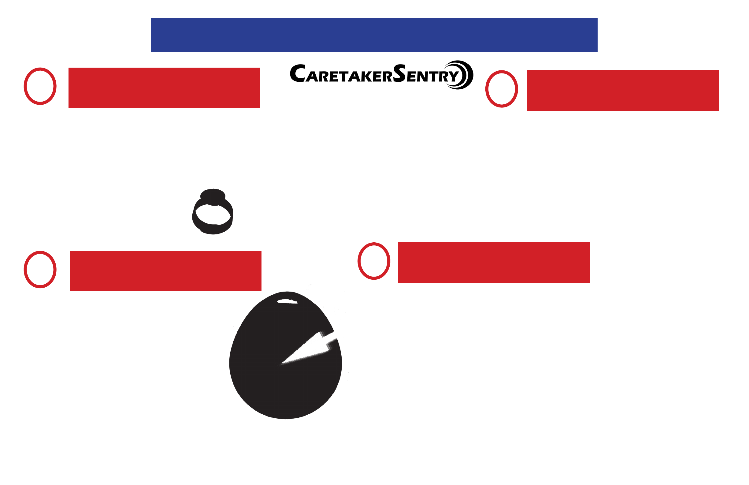
Pendant
Part #40915
Backup Batteries
Lanyard
Base Bottom View
DECT Pendant Battery Charging Port (for
Red Status LED
Master ON/OFF
Switch
optional accessrory)
Pendant Battery Charge Status LED
Instructions for Installing Your New Personal Emergency Response System
Equipment Reference Guide
Base Top View
Part #40914
Speaker
Battery Backup
Status (Yellow)
Phone Connection
(Blue)
Info (Green)
Power (Red)
Red Emergency button
Cancel (1 second)
System Check (8 seconds)
Blue CareTaker button
Breakaway
Feature
LogicMark Disclaimers and Limited Warranty
COMMUNICATION AND RESPONSE LIMITATIONS: Purchaser acknowledges that signals which are transmitted over telephone lines, or other modes of communica-
tion pass through communication networks wholly beyond the control of LogicMark LLC and are not maintained by LogicMark LLC, and, therefore, LogicMark LLC shall
not be responsible for any equipment or communication failure which prevents transmission signals from reaching your contact list including emergency 911 operators
or damages arising therefrom. Purchaser acknowledges that LogicMark LLC provides no response to the System’s equipment. The equipment is designed to communicate with the a central station of your choice and LogicMark LLC is not and shall not be responsible for ambulance, police or other emergency response time or that
any response will be provided by the central monitoring station.
TESTING AND SERVICE OF THIS EQUIPMENT: The equipment, once installed, are in the exclusive possession and control of the Purchaser, and it is Purchaser’s sole
responsibility to test the operation of equipment and request warranty service if the equipment is under warranty.
PURCHASER’S EXCLUSIVE REMEDY: Purchaser’s exclusive remedy for LogicMark LLC’s default hereunder is to require LogicMark LLC to repair or replace, at LogicMark
LLC’s option, any equipment or part of the personal emergency alert system which is non-operational during LogicMark LLC’s warranty period.
LIMITATION OF LIABILITY: This equipment is not designed or guaranteed to prevent any loss or injury. This Limited Warranty and Disclaimer of Liability constitutes the
terms of sale and use of the equipment, and if there should arise any liability on the part of LogicMark LLC as a result of any cause whatsoever, regardless of whether
or not such loss, damage, or personal injury was caused by or contributed to by LogicMark LLC’s negligence to any degree or failure to perform any obligation or strict
products liability, such liability will be limited to an amount paid by the Purchaser to LogicMark LLC for the product, or to the sum of $350.00, whichever is greater.
Gray Emergency Button
2 Second Push
Caretaker Sentry Base Unit - Model 40914
FCC ID: TYD-CS40914
IC ID: IC: 8471A-CS40914
Caretaker Sentry Standard Pendant - Model 40915
FCC ID: TYD-CS40915
IC ID: IC: 8471A-CS40915
Base Back View
Telephone Jacks
Line IN To House
Phone
Programming Switch
Programming Mode “Emergency Call Mode”
Code Learn
(Red)
Reset
Power DC 7.5
800 mAh
Normal Operation
Microphone
Base Side
View
For warranty information, see your delaer for details.
© LogicMark, LLC v3.8
Cell Accessory Plug
1
CaretakerSentry Step-by-Step Installation
Confirm Accessories in Kit
Model #40911
Plug Telephone Line and
3
Power Cord into Wall Jacks
4 Rechargable AA
Batteries
Lanyard
2
Telephone Cord
Wrist strap
Place Batteries in Unit.
OFF
ON
AC Adapter
To
Line
Plug the AC Adapter
power cord into the power
jack and twist right to lock.
in
4
House
Phone
(OPTIONAL) Plug
the telephone
into the “To House
Phone” jack.
Test the Unit
Performing a System Test
a. PUSH and HOLD the CANCEL button for 8-10 seconds to enter “System Check”
b. Push GRAY EMERGENCY button for 2 seconds on Pendant
(RED LED on the pendant should turn ON for 1 second)
c. Listen for voice prompt from base unit:
i. “All Systems are OK – Battery is OK” is heard system is correctly installed
ii. If any other voice prompt is heard, the unit will describe the problem
d. Push and release the CANCEL button for 1 second to exit Test Mode
(unit will automatically exit in 3 minutes)
Place Green Rechargeable batteries in the
compartment on the bottom of the base
unit. Make sure to turn ON/OFF switch
to ON. You will hear the announcement
“Running on Battery Power.” Unit will
do so until the AC Adapter pwer supply
is plugged in.
e. We recommend that you perform this System Test weekly
Place call to Emergency Operator:
a. Push GRAY EMERGENCY button for 2 seconds on Pendant (RED LED
on the pendant should turn ON for 1 second)
b. You should hear a dial tone, dialing and then communication tones
between the CaretakerSentry and central station. Several seconds later
the operator should answer the call and ask “Is everything OK”
c. Talk normally to the base unit – just like speaker phone
d. At the end of the conversation, the CaretakerAlert should automatically
hang-up – if not, push the CANCEL button for 1 second.

Information The FCC Wants You To Know: Information The FCC Wants You To Know:
Caretaker Sentry Base Unit - Model 40914
FCC ID: TYD-CS40914
IC: 8471A-CS40914
Caretaker Sentry Standard Pendant - Model 40915
FCC ID: TYD-CS40915
IC: 8471A-CS40915
Changes or modications not expressly approved by the party responsible for compliance could void
the user’s authority to operate the equipment.
This device complies with Part 15 of the FCC Rules. Operation is subject to the following two conditions:
(1) this device may not cause harmful interference, and (2) this device must accept any interference
received, including interference that may cause undesired operation.
This equipment has been tested and found to comply with the limits for a Class B digital device, pursuant to Part 15 of the FCC Rules. These limits are designed to provide reasonable protection against
harmful interference in a residential installation. This equipment generates uses and can radiate radio
frequency energy and, if not installed and used in accordance with the instructions, may cause harmful
interference to radio communications. However, there is no guarantee that interference will not occur
in a particular installation. If this equipment does cause harmful interference to radio or television
reception, which can be determined by turning the equipment off and on, the user is encouraged to
try to correct the interference by one of the following measures:
- Reorient or relocate the receiving antenna.
- Increase the separation between the equipment and receiver.
- Connect the equipment into an outlet on a circuit different from that to which the receiver is connected.
- Consult the dealer or an experienced radio/TV technician for help.
This portable transmitter with its antenna complies with FCC/IC RF exposure limits for general population/uncontrolled exposure.
This Device complies with Industry Canada License-exempt RSS standard(s). Operation is subject to
the following two conditions: 1) this device may not cause interference, and 2) this device must accept
any interference, including interference that may cause undesired operation of the device.
Cet appareil est conforme à Industrie Canada exemptes de licence RSS ou les normes. Opération est
sujette aux deux conditions suivantes: 1) cet appareil ne doit pas brouillage et 2) cet appareil doit
accepter toute interférence reçue, y compris les interférences pouvant entraîner un fonctionnement
indésirable du dispositif.
This equipment complies with Part 68 of the FCC rules and the requirements adopted by the ACTA:
US: TBD
REN: TBD
Privacy of communications may not be ensured when using this product.
This product meets the applicable Industry Canada technical specications. / Le présent matériel est
conforme aux specications techniques applicables d’Industrie Canada.
The Ringer Equivalence Number (REN) is an indication of the maximum number of devices allowed to
be connected to a telephone interface. The termination of an interface may consist of any combination of devices subject only to the requirement that the sum of the RENs of all the devices not exceed
ve. / L’indice d’équivalence de la sonnerie (IES) sert à indiquer le nombre maximal de terminaux qui
peuvent être raccordés à une interface téléphonique. La terminaison d’une interface peut consister en
une combinaison quelconque de dispositifs, à la seule condition que la somme d’indices d’équivalence
de la sonnerie de tous les dispositifs n’excède pas cinq.
 Loading...