

RTCU AX9i eco
Technical Manual
Version 1.01

RTCU AX9i eco Technical Manual V1.01
Introduction
This manual contains technical documentation which allows for easy installation and use of the
RTCU AX9i eco product. For information on the programming and software configuration of the
product please refer to the RTCU IDE documentation.
The RTCU AX9i eco has been designed from the ground up for professional wireless industrial
applications with its strong on-board I/O capabilities and multiple communication interfaces such
as: 1-Wire, RS232 and USB. For world-wide usage in any network environment the RTCU AX9i eco
offers a full quad-band GSM engine with a switchable dual antenna design supporting both an onboard as well as an external GSM antenna.
The RTCU AX9i eco is based on the X32 Execution Architecture offering high performance and a
large memory capacity for both program and data - meeting the requirements of today’s most
demanding and sophisticated M2M/IoT applications.
The RTCU AX9i eco rests on the RTCU M2M Platform that brings all the necessary tools together
to develop, implement and maintain today’s sophisticated M2M/IoT applications.
The development task is supported by the free RTCU IDE development environment
complimented by a large and comprehensive documentation and application example library.
The RTCU Gateway 2 is the corner-stone of the communication infrastructure ensuring reliable
two-way device communication in any network environment.
Deploying and maintaining new application and firmware versions for devices in the field are
handled by the powerful RTCU Deployment Server.
For detailed information on the powerful RTCU M2M Platform, please refer to the
RTCU M2M Platform datasheet.
Logic IO ApS. Ph: (+45) 7625 0210
Holmboes Allé 14 Fax: (+45) 7625 0211
8700 Horsens Page 2 of 30 Email: support@logicio.com
Denmark www.logicio.com

RTCU AX9i eco Technical Manual V1.01
The technical highlights of the RTCU AX9i eco:
Based on the RTCU M2M Platform1
X32 execution architecture.
o RTCU IDE development tool with a full featured device simulator.
o Huge standard API with more than 800+ functions.
o Comprehensive protocol support, including:
TCP-UDP/IP, FTP, SMTP, RACP, MQTT.
World-wide Quad-band GSM engine.
Internal and external antenna connector. Selectable from application.
Internal SIM-card reader.
Digitized audio can be played over GSM.
DTMF support for implementation of Interactive Voice Response applications.
Large data-flash/logger memory with a capacity of 4.5 MB.
Internal 4 MB FAT32 flash drive.
1 x RS232 channel.
2 x analog inputs with 0..10 volt / 0..20 mA with 12 bit precision.
5 x digital inputs and 4 x high-power relays.
Up to 4 digital inputs can be configured as IEC62053-31 Class A compliant.
1-Wire bus for accessories such as ID-button reader, temperature sensors, etc.
Wide AC/DC power operating range from 85..265VAC / 8..36 VDC.
On-board Li-Ion battery.
Advanced power-management with wake-up on a wide range of events.
High-speed USB programming connector.
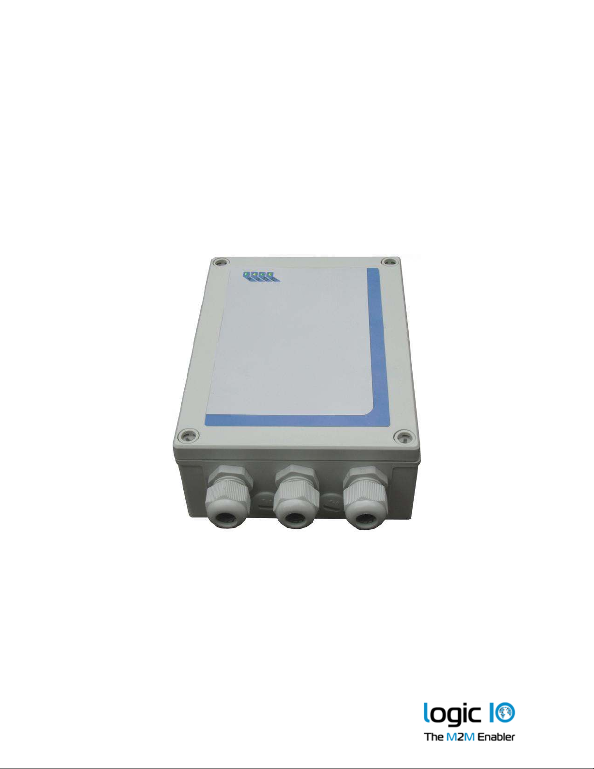
Housed in a ruggedized plastic encapsulation with cable glands.
IP65 water protected for outdoor usage.
Fully supported by the RTCU Gateway 2 and the RTCU Deployment Server
.
1 Please see “The RTCU M2M Platform” data sheet for more information.
Logic IO ApS. Ph: (+45) 7625 0210
Holmboes Allé 14 Fax: (+45) 7625 0211
8700 Horsens Page 3 of 30 Email: support@logicio.com
Denmark www.logicio.com

RTCU AX9i eco Technical Manual V1.01
* * * * THIS PAGE IS INTENTIONALLY LEFT BLANK * * *
Logic IO ApS. Ph: (+45) 7625 0210
Holmboes Allé 14 Fax: (+45) 7625 0211
8700 Horsens Page 4 of 30 Email: support@logicio.com
Denmark www.logicio.com

RTCU AX9i eco Technical Manual V1.01
Table of Contents
Introduction......................................................................................................................................................2
The technical highlights of the RTCU AX9i eco:.........................................................................................3
Graphical view.................................................................................................................................................6
Connection Overview.................................................................................................................................7
Power supply .................................................................................................................................................10
DC Supply ..................................................................................................................................................11
AC Supply..................................................................................................................................................12
Digital I/O .......................................................................................................................................................14
Relay outputs.............................................................................................................................................14
Load Noise .................................................................................................................................................14
Digital inputs / S0 inputs / wakeup (ignition) input.............................................................................15
Analog input ..................................................................................................................................................17
USB programming port ................................................................................................................................18
RS232 communication ports (EIA/TIA-232 and V.28/V.24 compatible) ................................................18
RS232 port 1 ...............................................................................................................................................18
1-Wire bus.......................................................................................................................................................19
LED Indicators ...............................................................................................................................................19
User LED A and B .....................................................................................................................................19
System LED S1 and S2..............................................................................................................................20
Switches ..........................................................................................................................................................21
DIP-Switch..................................................................................................................................................21
System switch (RST)..................................................................................................................................21
Internal Li-Ion battery...................................................................................................................................22
GSM .................................................................................................................................................................23
GSM Antenna ............................................................................................................................................23
SIM-Card.........................................................................................................................................................24
Barcode / unit type ........................................................................................................................................24
Power consumption ......................................................................................................................................25
External DC supply...................................................................................................................................25
Internal battery ..........................................................................................................................................25
External AC supply...................................................................................................................................26
Appendix A – Unit configuration guide ....................................................................................................27
Appendix B – Installing the SIM card.........................................................................................................29
RTCU AX9i eco Specifications.....................................................................................................................30
Logic IO ApS. Ph: (+45) 7625 0210
Holmboes Allé 14 Fax: (+45) 7625 0211
8700 Horsens Page 5 of 30 Email: support@logicio.com
Denmark www.logicio.com

RTCU AX9i eco Technical Manual V1.01
System LED
s
Graphical view
On the front of the RTCU AX9i eco are four user controlled LED’s and three system LED’s for
simple information and status.
The external GSM antenna connector is located at the side of the device as shown below:
User Controlled
LEDs
Logic IO ApS. Ph: (+45) 7625 0210
Holmboes Allé 14 Fax: (+45) 7625 0211
8700 Horsens Page 6 of 30 Email: support@logicio.com
Denmark www.logicio.com

RTCU AX9i eco Technical Manual V1.01
VAC terminal
Fuse
LED’s
USB-B
Angl
ed
and blinds
Connection Overview
Connections to external equipment are done via large and easy-to-use screw terminal blocks which
are accessible when the lid is removed. The placement of the terminals makes installation easy
using the PG glands and thereby maintaining the IP-67 protection.
The RTCU AX9i eco is delivered with three PG11 glands and additional two PG9 blind plugs that
can be replaced with PG9 glands if additional cable entry capacity should be required.
PG Glands
Internal GSM
Antenna
External SMA
GSM Antenna
connector
Stacked
Terminals
Configuration
Jumpers
Terminals
DIP
Switches
SIM card
reader
The stacked terminals contain connections for: digital inputs/outputs, analog inputs and DC power
input.
The angled terminals contain connections for the communication interfaces: RS232 Port 1 and 1Wire.
Also located inside the RTCU AX9i eco are the SIM card reader, DIP switches and a USB-B highspeed programming connector.
Logic IO ApS. Ph: (+45) 7625 0210
Holmboes Allé 14 Fax: (+45) 7625 0211
8700 Horsens Page 7 of 30 Email: support@logicio.com
Denmark www.logicio.com

RTCU AX9i eco Technical Manual V1.01
Stacked terminal overview
Terminal Name
Description
TOP row BOT row
R1A
Contact set for relay output 1
R1B
R2A
Contact set for relay output 2
R2B
R3A
Contact set for relay output 3
R3B
R4A
Contact set for relay output 4
R4B
N.C Not connected
PE Protective Earth terminal for AC supply.
DCIN DC power supply, positive (+) connection
XGND DC power ground, negative (-) connection
DCOUT12 Internally not connected
GND Signal ground
DI1 Digital input 1 / S0 input 1
DI2 Digital input 2 / S0 input 2
DI3 Digital input 3 / S0 input 3
DI4 Digital input 4 / S0 input 4
DI5 Digital input 5 / Wakeup (ignition) input
GND Signal ground
AI1 Analog input 1
AI2 Analog input 2
AGND Analog ground
AGND Analog ground
Logic IO ApS. Ph: (+45) 7625 0210
Holmboes Allé 14 Fax: (+45) 7625 0211
8700 Horsens Page 8 of 30 Email: support@logicio.com
Denmark www.logicio.com
RTCU AX9i eco Technical Manual V1.01
Angled terminal front row overview
Terminal Name Description
SER1_TXD Transmit data from serial port 1, RS232 compatible
SER1_RXD Receive data for serial port 1, RS232 compatible
DEV_DET Reserved for accessories.
SGND Signal ground
1Wire 1-Wire bus for ID-Button / Temperature sensor
1Wire-LED 1-Wire ID-Button LED output
VAC terminal overview
Terminal Name Description
N
N
P
P
85-265VAC (50/60Hz) Null input
(internally connected)
85-265VAC (50/60Hz) Phase input
(internally connected)
USB-B connector
This is a standard USB-B connector and is used for communicating with the RTCU IDE (or other
RACP compliant application).
Logic IO ApS. Ph: (+45) 7625 0210
Holmboes Allé 14 Fax: (+45) 7625 0211
8700 Horsens Page 9 of 30 Email: support@logicio.com
Denmark www.logicio.com

RTCU AX9i eco Technical Manual V1.01
Power supply
The RTCU AX9i eco unit can be supplied with either 85-265VAC (50/60Hz) or 8-36VDC or both
supply types simultaneously.
The RTCU AX9i eco also contains an internal low capacity backup battery, which will supply the
RTCU if the external power should fail or be disconnected. By default the RTCU AX9i eco is
powered down when a power fail occur. This setting however can be changed. Please consult the
RTCU-IDE on-line help for more information.
When the wakeup/ignition input is activated with a logical high, the RTCU AX9i eco unit will
wake up if it was in power down mode.
There are five different ground labels: External Ground (XGND), Signal Ground (SGND), Digital
Ground (GND), Analog Ground (AGND) and AC power ground (PE). The signal, digital and
analog grounds are filtered from the power ground. The signal, digital and analog grounds are
filtered from the power ground. External ground must only be used as DC power supply return
path. The digital ground is used as ground reference for digital I/O’s, signal ground is used as
ground reference for serial interfaces, and the analog ground is used as a low noise analog ground
reference for the analog inputs.
Dual Supply Note:
The RTCU AX9i eco unit can be supplied with both VAC and VDC at the same time. The unit will
run on the VAC supply if the VDC supply voltage is < +16VDC. If the VDC supply voltage is
higher it will run on the VDC supply.
Please refer to the RTCU on-line help for information on how to check the supply type from within
an application.
Logic IO ApS. Ph: (+45) 7625 0210
Holmboes Allé 14 Fax: (+45) 7625 0211
8700 Horsens Page 10 of 30 Email: support@logicio.com
Denmark www.logicio.com

RTCU AX9i eco Technical Manual V1.01
DC Supply
The RTCU AX9i eco unit can be supplied with 8-36VDC from an external DC power source.
Positive power is applied to the DCIN pin and ground is connected to the XGND pin.
The DC supply of the RTCU AX9i eco is protected against wrong polarity. If a system ground are
connected to either SGND or AGND a wrong polarity on the supply lines will destroy the internal
GND connection.
Please Note:
Minimum 16VDC supply is necessary for digital inputs 1-4 to work as S0 compliant inputs.
VDC Supply terminals
Terminal Name Description
DCIN Power supply, positive (+) connection
XGND Power ground, negative (-) connection
Logic IO ApS. Ph: (+45) 7625 0210
Holmboes Allé 14 Fax: (+45) 7625 0211
8700 Horsens Page 11 of 30 Email: support@logicio.com
Denmark www.logicio.com
RTCU AX9i eco Technical Manual V1.01
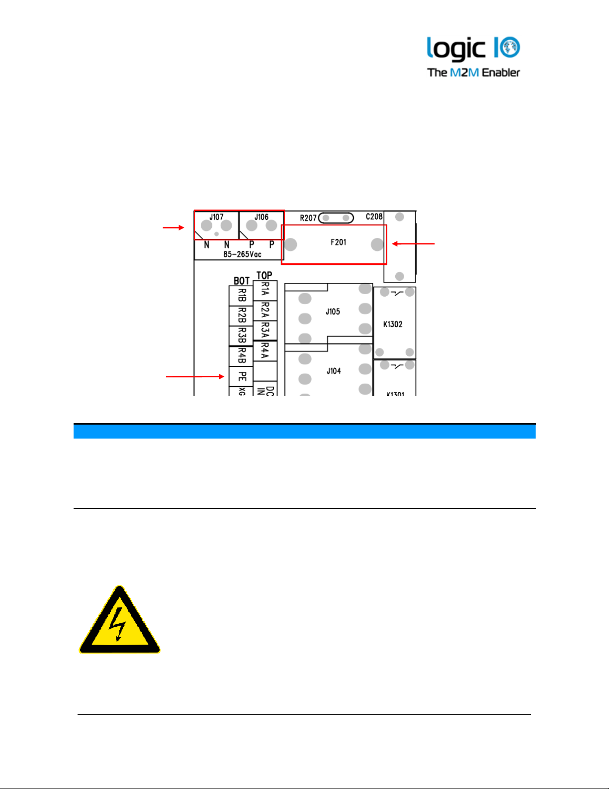
AC Supply
The RTCU AX9i eco unit can be supplied with 85-265VAC (50/60Hz) from a standard wall plug or
any other high-voltage VAC power rail. The AC supply of the RTCU AX9i eco is a high-efficient
switch mode power supply and the AC input is protected with a 1A/250V Fast Acting fuse.
The AC must be applied between the N and P on the separate located screw terminals. A
Protective Earth (PE) connection exists on the bottom row of the stacked terminals.
VAC terminal
1A/250V Fast
Acting fuse
Protective Earth
terminal
VAC Supply terminals
Terminal Name Description
N
N
P
P
85-265VAC (50/60Hz) Null input
(internally connected)
85-265VAC (50/60Hz) Phase input
(internally connected)
PE Protective Earth connector
Please Note:
The two pairs of N and P terminals are internally connected.
There is high voltage on certain areas of the PCB (Printed Circuit Board) when supplied with AC
mains. There is risk of electrical hazard, avoid touching the PCB and the
components during operation.
Be aware that the supply filter contains capacitors that may remain charged
after the equipment is disconnected from the supply. Although the stored
energy is within the approved safety requirements, a slight shock may be felt if
the plug pins are touched immediately after removal.
Refer all servicing and handling to qualified personnel.
Logic IO ApS. Ph: (+45) 7625 0210
Holmboes Allé 14 Fax: (+45) 7625 0211
8700 Horsens Page 12 of 30 Email: support@logicio.com
Denmark www.logicio.com

RTCU AX9i eco Technical Manual V1.01
Please Note:
The DC ground of the AX9 series is isolated from the AC ground because of the nature of AC-toDC converting. As these two grounds are not tied together anywhere in the AX9, the DC ground
may appear as "floating ground" to the outside if the AX9 ground is not connected to the same
reference as the outside, and a potential difference may occur. This difference can interrupt the
behavior of the unit, and in worst case can damage the part of the unit. This must be taken in
consideration when the AX9 series are supplied with AC supply. When the AX9 is supplied with
DC voltage this "potential difference" issue may not be observed, as the DC power supply has
usually the same potential as the rest of the system.
In order to avoid the potential difference the Earth connection on the AC supply rail can be
connected to the terminal that has been labeled “PE”.
For circuitry in situations where significant Earth ground currents can flow isolating the DC
ground from Earth grounds may be desired. In this case the DC ground may be tied together with
the Earth ground through a high impedance connection.
In other situations where a common reference needed the best EMI performance and ESD
immunity can be achieved connecting the DC ground and Earth ground with a low-inductance
connection.
Logic IO ApS. Ph: (+45) 7625 0210
Holmboes Allé 14 Fax: (+45) 7625 0211
8700 Horsens Page 13 of 30 Email: support@logicio.com
Denmark www.logicio.com

RTCU AX9i eco Technical Manual V1.01
Digital I/O
The RTCU AX9i eco unit has five digital inputs and four normally-open relay outputs.
The outputs are high performance relays with good current handling capabilities.
Digital input 1-4 offers several operation modes. Please refer to the digital input section for
additional information.
Relay outputs
The digital outputs control four relays and they act like a normally-open contact, where one side
must be connected to a source that needs switching and the other contact terminal is the output.
The source can be either VAC or VDC but the maximum switchable voltage and current must not
be exceeded, please refer to specification page.
There are no internal connections to the relay outputs and therefore a source must always be
connected to one of the relay terminals for the output to work. If power is removed or a power-fail
occurs on the RTCU AX9i eco will switch to normally-open.
The RTCU AX9i eco unit offers a very advanced power management, which makes it possible to
have one or more outputs enabled while the RTCU is in low power mode. Please consult the RTCU
IDE on-line help for more information.
Relay output terminals
Terminal Name Description
R1A
R1B
R2A
R2B
R3A
R3B
R4A
R4B
Contact set for relay output 1
Contact set for relay output 2
Contact set for relay output 3
Contact set for relay output 4
Load Noise
If highly inductive loads (such as high power contactors) are connected to the relays it is
recommended to externally connect a clamping diode in parallel with each inductive DC load or
connect an RC snubber circuit in parallel with each inductive AC load.
For DC applications Vishay UF5405-E3/54 or similar is recommended and for AC applications
AMPOHM FE-SP-HDR23-47/100 (47nF/100 ohm) or similar is recommended.
Logic IO ApS. Ph: (+45) 7625 0210
Holmboes Allé 14 Fax: (+45) 7625 0211
8700 Horsens Page 14 of 30 Email: support@logicio.com
Denmark www.logicio.com

RTCU AX9i eco Technical Manual V1.01
Digital inputs / S0 inputs / wakeup (ignition) input
The five digital inputs are all low-pass filtered (450kHz) and transient-protected. To activate the
inputs, connect a positive voltage between the corresponding input (DINx) and SGND.
Digital input 1-4 can be configured individually as S0 input (IEC62053-31, Class A) and DIN5 can
work as a wakeup (ignition) input.
As default the digital inputs are configured as normal inputs. For placement and configuration of
the hardware jumpers inside the unit, please refer to the configuration guide in Appendix A.
S0 compliant inputs (IEC62053-31, Class A compatible)
In S0 configuration the relevant RTCU AX9i eco input will act as a ‘pulse input device’, and a
current is supplied into the input connector so that a simple switch between SGND and the
appropriate input will activate it. This is used in most electricity metering equipment.
Please note: The RTCU AX9i eco unit must be supplied with a minimum of 16 VDC or AC power
for the S0 mode to work correctly.
S0 is enabled by default and may be disabled by the application to save power.
Logic IO ApS. Ph: (+45) 7625 0210
Holmboes Allé 14 Fax: (+45) 7625 0211
8700 Horsens Page 15 of 30 Email: support@logicio.com
Denmark www.logicio.com

RTCU AX9i eco Technical Manual V1.01
Wakeup (ignition) input
The DIN5 / wakeup (ignition) input is a special input in that it also functions as the wakeup input.
If the input is activated with a logical high or low (Wait For Event mode only) when the RTCU
AX9i eco is in low-power mode it will wake-up the unit. A power apply will also wake the unit up
if it is in power-down mode or in Wait For Event mode with power Apply and/or ignition selected
for wakeup. The input is de-bounced with a period between 1-2 ms when used as a digital input.
So any logical level applied to this input must be greater than 2 ms to be valid.
The power management allows for the possibility of configuring a wakeup on one or more digital
inputs with individually configured falling- or rising edge detection. Please consult the RTCU IDE
on-line help for more information.
Digital input terminals
Terminal Name Description Jumper Setting
DI1 Digital input 1 or
S0 input 1
DI2 Digital input 2 or
S0 input 2
DI3 Digital input 3 or
S0 input 3
DI4 Digital input 4 or
S0 input 4
DI5 Digital input 5 and
JPDI1 in position N (default)
JPDI1 in position S
JPDI2 in position N (default)
JPDI2 in position S
JPDI3 in position N (default)
JPDI3 in position S
JPDI4 in position N (default)
JPDI4 in position S
Wakeup (ignition) input
GND Digital Ground
For placement and configuration of the hardware jumpers inside the unit, please refer to the unit
configuration guide in Appendix A.
Logic IO ApS. Ph: (+45) 7625 0210
Holmboes Allé 14 Fax: (+45) 7625 0211
8700 Horsens Page 16 of 30 Email: support@logicio.com
Denmark www.logicio.com

RTCU AX9i eco Technical Manual V1.01
Analog input
The RTCU AX9i eco unit has two analog inputs which can be configured individually to work
either as voltage or current measurement inputs by using the configuration jumper. The range in
voltage mode is 0-10VDC and in current mode it is 0-20mA.
The conversion resolution is 12 bit.
By default the analog inputs are configured as voltage inputs, and are converted to a digital value
with a resolution of 10-bit before being presented to the application (0..1023). The application can
change the resolution to the full 12 bit (0..4095). Please consult the RTCU IDE for further details.
The input signal is connected between AINx and AGND. AGND must be connected to the
reference of the connected equipment. Please be aware that deviations may occur, as the system is
very noise sensitive. Avoid long, unshielded wires and high current, fast changing signals routed
parallel to the analog signals.
Analog input terminals
Terminal Name Description Jumper Setting
AI1 Analog input 1 – Voltage
Analog input 1 – Current
AI2 Analog input 2 – Voltage
Analog input 2 – Current
AGND Analog ground
AGND Analog ground
Specification for each analog input (voltage mode)
Min. Typ. Max. Unit
0
Resolution
- -
Precision -1.5
Cut-off frequency
Input impedance
-
-
-
-
4.5
40
10 VDC
12 Bit
1.5 %FSR
-
-
kHz
kΩ
Specification for each analog input (current mode)
Min. Typ. Max. Unit
0
Resolution
- -
Precision -1.5
Cut-off frequency
Input impedance
-
-
-
-
4.5
504
20 mA
12 Bit
1.5 %FSR
-
-
kHz
Ω
For placement and configuration of the hardware jumpers inside the unit, please refer to the unit
configuration guide in Appendix A.
JPAI1 not installed (default)
JPAI1 installed
JPAI2 not installed (default)
JPAI2 installed
Protected against transients and
low-pass filtered
Precision is based on
measurements @ 25 ˚C
Protected against transients and
low-pass filtered
Precision is based on
measurements @ 25 ˚C
Logic IO ApS. Ph: (+45) 7625 0210
Holmboes Allé 14 Fax: (+45) 7625 0211
8700 Horsens Page 17 of 30 Email: support@logicio.com
Denmark www.logicio.com

RTCU AX9i eco Technical Manual V1.01
USB programming port
The USB port is for programming and communicating with the RTCU IDE (or other RACP
compliant application). A standard USB cable can be used between the unit and the PC.
RS232 communication ports (EIA/TIA-232 and V.28/V.24 compatible)
One general purpose RS232 ports available on the RTCU AX9i eco unit. The serial input is
compliant with the EIA/TIA-232 standard.
RS232 port 1
This port is a general-purpose RS232 serial port and does not support handshaking.
The signals are available on the angled front row terminals.
SER1 terminals
Terminal Name Description
SER1_TXD Transmit data from serial port 1, RS232 compatible
SER1_RXD Receive data for serial port 1, RS232 compatible
SGND Signal ground
Logic IO ApS. Ph: (+45) 7625 0210
Holmboes Allé 14 Fax: (+45) 7625 0211
8700 Horsens Page 18 of 30 Email: support@logicio.com
Denmark www.logicio.com

RTCU AX9i eco Technical Manual V1.01
1-Wire bus
The 1-Wire bus is available on the angled front row terminals. All 1-Wire communication goes
through a single connection, and all 1-Wire devices connected to this connection retrieves its
power directly from the bus (called parasitic power). For this only two wires are needed – the 1wire signal and the ground reference – allowing minimal cable installations.
For 1-Wire ID-Button readers, which include a built-in LED, a dedicated output is available for this
purpose. Please consult the RTCU IDE documentation for further information.
For further information regarding modular 1-wire concept, please refer to the document “Modular
1-Wire Concept Technical Manual” on the Logic IO webpage.
1-Wire terminals
Name Description
1Wire 1-Wire bus
1Wire-LED 1-Wire ID-Button LED output
SGND Signal ground
LED Indicators
Three bi-colored (red and green) and a single yellow LED indicators are present on the front of the
unit (see graphical view section).
Two bi-colored LED’s (A and B) are available to the user and the remaining two LED’s (S1 and S2)
are indicating the status and possible errors of the RTCU unit.
User LED A and B
LED A and B are composed of four individually controllable LEDs:
• LED named A on the front consists of LED 1 (green) and LED 2 (red).
• LED named B on the front consists of LED 3 (green) and LED 4 (red).
They are easily accessed from within the application program, and it is possible to mix the LED’s
to obtain a third color: yellow. Please consult the RTCU IDE documentation for more information.
Logic IO ApS. Ph: (+45) 7625 0210
Holmboes Allé 14 Fax: (+45) 7625 0211
8700 Horsens Page 19 of 30 Email: support@logicio.com
Denmark www.logicio.com

RTCU AX9i eco Technical Manual V1.01
System LED S1 and S2
The RTCU is equipped with two system LED’s which shows the status and possible errors of the
RTCU unit.
The different patterns are listed in the table below. If the color of the system LED S1 is yellow, the
unit is actively communicating with the RTCU IDE (or another program, supporting the RTCU
RACP protocol).
The single yellow LED is signaling either the GSM module activity, or if all other LED’s are off,
that the RTCU is in the “wait for event” low power state.
S1: System LED1 pattern overview
Pattern Description
Fastest blinking, green The unit is initializing, preparing to start the application.
Fast blinking, green2 The unit has been forced into recovery mode with the use of
the system switch. The application is not executing.
500ms On / 500ms Off green2 The unit is executing the application program
1.5s On / 0.5s Off. green2 The unit is executing the application program, while
charging the internal back-up battery.
Fast blinking, red2 A runtime error has been detected in the program.
Use the RTCU IDE to obtain the fault log.
Alternating Fast/Slow, red2 The unit has lost its firmware! This can only happen if,
during a firmware upgrade, the RTCU unit loses power or
the communication is lost completely. In this case, simply
upload the firmware to the unit again.
75ms On / 925ms Off, green Execution speed is different from full-speed.
S2: System LED2 pattern overview (GSM activity and “Wait For Event”)
Pattern Operating Status
Off The GSM module is turned off
600 ms On / 600 ms Off Missing SIM card or PIN code.
Network search and logon in progress.
75 ms On / 3 s Off Logged on to the network.
75 ms On / 75 ms Off /
A GPRS session is active.
75 ms On / 3 s OFF
Flashing Indicates GPRS data transfer.
On A voice or CSD session is active.
8 s OFF / 10 ms ON
The RTCU unit is in low-power “Wait For Event” state.
(and all other LED’s OFF)
2 Or yellow when communicating with the RTCU IDE or another program, supporting the RTCU RACP protocol).
Logic IO ApS. Ph: (+45) 7625 0210
Holmboes Allé 14 Fax: (+45) 7625 0211
8700 Horsens Page 20 of 30 Email: support@logicio.com
Denmark www.logicio.com

RTCU AX9i eco Technical Manual V1.01
DIP switch
Switches
DIP-Switch
The RTCU AX9i eco unit contains four dipswitches, where three of them are available for the
application to use (fourth dipswitch is reserved for GSM antenna switching.) The dipswitches are
located inside the unit (see drawing below or graphical view)
System switch (RST)
The RTCU AX9i eco unit contains a combined reset/diagnostic switch. This switch is accessible
from the inside of the unit (see drawing below or graphical view) It's necessary to use a small object,
for example the tip of a pencil.
By activating the switch shortly the RTCU unit will do a complete reset, as if the power was
removed and reapplied.
If the reset switch is held down for approx. 3 seconds3 the unit will enter recovery mode4 where the
application will not be started. In recovery mode the system will automatically turn on the GSM
module to establish a connection to the GSM network and RTCU Gateway (if configured). This
method will also activate the unit when the unit is in power-down mode.
System switch
3 System LED S2 will flash three times when this state is entered.
4 System LED S1 will indicates this state by fast blinking green or yellow.
Logic IO ApS. Ph: (+45) 7625 0210
Holmboes Allé 14 Fax: (+45) 7625 0211
8700 Horsens Page 21 of 30 Email: support@logicio.com
Denmark www.logicio.com

RTCU AX9i eco Technical Manual V1.01
Internal Li-Ion battery
The RTCU contains an internal Li-Ion battery for operation even when the external power is absent
making it possible to report power loss etc. Please note that when external power is removed, the
unit will be powered down by default. This setting can be changed as documented in the RTCU
IDE documentation.
The relay outputs will be disabled when a power fail occurs as the internal battery cannot provide
the supply voltage needed.
The battery charging is completely automated and handled internally by the RTCU unit – leaving
no need for user interaction. Different kinds of functions (Battery low, Charger enable, Charging
status, etc.) are available to the user application.
The charge current is relatively high, for a shorter charge time, as specified in the technical
specification. Make sure both power supply and cables can handle the high current.
The battery will be charged whenever a power fail has occurred to establish the capacity thus
making the battery ready for the next power fail. A maintenance charge will start every 20 days
after the last charge. This is to compensate for the battery self-discharge etc.
By default the battery cannot be charged above 45°C or below 0°C. The RTCU offers charging
down to -10 ˚C using a specialized algorithm to protect the battery.
If the temperature is above 45°C the charging will not start and will be postponed until it is below
this threshold.
The temperature has a very high influence on the battery capacity. At 0°C the capacity has
dropped to 60% of the initial capacity and it falls dramatically at lower temperatures.
The battery cycle (numbers of charges and discharges) also influences the capacity. After 300
cycles the capacity has dropped to approximately 80% of the initial capacity.
Warning
Misusing the RTCU unit may cause the built-in battery security circuit to be damaged.
• Do not place the RTCU unit in high temperature locations such as in direct sunlight or near
engines. Using the RTCU unit in this environment may result in loss of battery performance and a
shortened life expectancy.
• Do not expose the unit to water, salt water or allow the battery to get wet.
• Avoid strong impacts and shocks.
For more information regarding the environmental limitations, see “Specifications for RTCU AX9i
eco” below or consult the RTCU AX9i eco datasheet.
Logic IO ApS. Ph: (+45) 7625 0210
Holmboes Allé 14 Fax: (+45) 7625 0211
8700 Horsens Page 22 of 30 Email: support@logicio.com
Denmark www.logicio.com

RTCU AX9i eco Technical Manual V1.01
GSM
For GSM and GPRS communication an industry leading QUAD band (850/900/1800/ 1900MHz)
GSM module is used.
The RTCU AX9i eco supports:
• Digitized voice
• SMS (Text and PDU)
• GPRS Multislot class 10. Support for simultaneous Voice and GPRS (suspended)
• CSD (Datacall)
GSM Antenna
The RTCU AX9i eco offers support for both an on-board internal GSM antenna and a user supplied
external antenna connected to the SMA female connector at the top of the encapsulation.
The active antenna can be selected by the application using the gsmSetAntennaMode function or
alternatively with a DIP switch. By default when the unit is delivered the active antenna can be
selected by DIP switch 4 and is set for external antenna.
Location of the internal/external GSM antenna and the DIP-switch 4:
Internal
Antenna
DIPswitch 4
External
Antenna
SMA
Logic IO ApS. Ph: (+45) 7625 0210
Holmboes Allé 14 Fax: (+45) 7625 0211
8700 Horsens Page 23 of 30 Email: support@logicio.com
Denmark www.logicio.com

RTCU AX9i eco Technical Manual V1.01
GSM antenna selection
gsmAntennaMode DIP-switch 4 GSM Antenna
1 Ignored Internal antenna
2 Ignored External antenna
3
On Internal antenna
Off External antenna
Please refer to the RTCU IDE online help for further information on gsmSetAntennaMode.
When installing the RTCU AX9i eco please make sure that the antenna is not in close proximity of
metallic parts or anything else that can influence the efficiency of the GSM antenna.
SIM-Card
The RTCU AX9i eco unit contains a standard SIM card reader which is located inside the unit (see
graphical view) and is easily accessed. The SIM card reader is lid based with a mechanical lock
system for secure installation of the SIM card. Please refer to Appendix B for SIM card installation
guide.
Barcode / unit type
The barcode label found on the RTCU AX9i eco unit contains the serial number.
The first three digits in the serial-number identify the unit type, as follows:
• 268: RTCU AX9i eco
The barcode format used: 2/5 Interleaved with Check Digit
Logic IO ApS. Ph: (+45) 7625 0210
Holmboes Allé 14 Fax: (+45) 7625 0211
8700 Horsens Page 24 of 30 Email: support@logicio.com
Denmark www.logicio.com
RTCU AX9i eco Technical Manual V1.01
Power consumption
Detailed information on the maximum power consumption of the RTCU AX9i eco unit in different
states and different supply types is listed below.
Please Note: Values marked with (*) is average and should be considered as guidelines as they
may vary depending on the GSM signal strength.
External DC supply
When the RTCU AX9i eco unit is powered from an external DC power source the power
consumptions will be as follows.
Maximum power consumption
8V 12V 30V
Unit active 65 50 20 mA
Unit active with GSM on* 80 60 25 mA GSM idle @ -67dBm*
Unit active RF sending 65 55 20 mA
Unit active while charging 870 530 290 mA
Unit in power-down 1.3 0.8 0.4 mA Restart on DIN5, RTC
Unit in “wait for event” 1.3 0.8 0.4 mA Resume on DIN, RTC
Unit in “wait for event” 10 6 3 mA Resume on RS232
Unit in “wait for event” 26 20 8 mA Resume on GSM activity
Internal battery
If the external power source is removed and the internal battery is enabled the power consumption
from the battery will be as listed below.
Maximum power consumption
BAT
Unit active 85 mA
Unit active with GSM on* 105 mA GSM idle @ -67dBm*
Unit in power-down 1.5 mA Restart on DIN5, RTC
Unit in “wait for event” 1.5 mA Resume on DIN, RTC
Unit in “wait for event” 12 mA Resume on RS232
Unit in “wait for event” 35 mA Resume on GSM activity
Note: Power consumption from a fully charged battery.
Logic IO ApS. Ph: (+45) 7625 0210
Holmboes Allé 14 Fax: (+45) 7625 0211
8700 Horsens Page 25 of 30 Email: support@logicio.com
Denmark www.logicio.com
RTCU AX9i eco Technical Manual V1.01
External AC supply
When the RTCU AX9i eco unit is powered from an external AC the power consumptions will be as
follows:
Maximum power consumption
220VAC
Unit active 8 VA
Unit active with GSM on* 8.5 VA GSM idle @ -67dBm*
Unit active RF sending 8.3 VA
Unit active while charging 17.2 VA
Unit in power-down 6.6 VA Restart on DIN5, RTC
Unit in “wait for event” 6.6 VA Resume on DIN, RTC
Unit in “wait for event” 7 VA Resume on RS232
Unit in “wait for event” 7 VA Resume on GSM activity
Logic IO ApS. Ph: (+45) 7625 0210
Holmboes Allé 14 Fax: (+45) 7625 0211
8700 Horsens Page 26 of 30 Email: support@logicio.com
Denmark www.logicio.com

RTCU AX9i eco Technical Manual V1.01
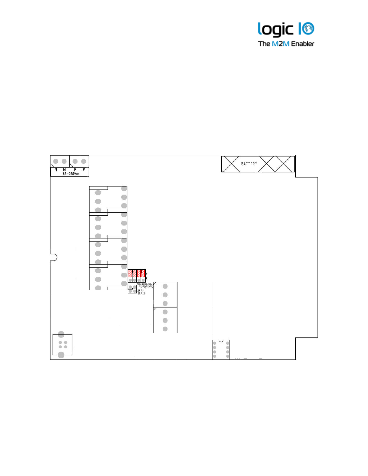
Appendix A – Unit configuration guide
The RTCU AX9i eco has many features and some of them require configuration by using hardware
jumpers inside the unit. A brief overview over the jumper settings can be found on the following
table:
Feature Jumper State Default state
Analog input
Digital input
JPAI1 Installed
Not installed
JPAI2 Installed
Not installed
JPDI1 Position S
Position N
JPDI2 Position S
Position N
JPDI3 Position S
Position N
JPDI4 Position S
Position N
AI1 current measurement
AI1 voltage measurement (default)
AI2 current measurement
AI2 voltage measurement (default)
DI1 S0
DI1 normal (default)
DI2 S0
DI2 normal (default)
DI3 S0
DI3 normal (default)
DI4 S0
DI4 normal (default)
Logic IO ApS. Ph: (+45) 7625 0210
Holmboes Allé 14 Fax: (+45) 7625 0211
8700 Horsens Page 27 of 30 Email: support@logicio.com
Denmark www.logicio.com
RTCU AX9i eco Technical Manual V1.01
JPAI1 and JPAI2
These jumpers are used to select between current and voltage input. With a jumper installed on the
relevant analog input it will measure current between 0-20mA.
JPDI1, JPDI2, JPDI3 and JPDI4
These select either normal or Class A S0 input for DIN1-4. With the relevant jumper installed in
position “S” the input is configured to S0, when installed in position “N” the input is a normal
digital input.
The following figure shows the location of the jumpers when the lid of the unit is removed. Red
lined boxes show default state of the jumpers.
Logic IO ApS. Ph: (+45) 7625 0210
Holmboes Allé 14 Fax: (+45) 7625 0211
8700 Horsens Page 28 of 30 Email: support@logicio.com
Denmark www.logicio.com

RTCU AX9i eco Technical Manual V1.01
Lock
Open
Appendix B – Installing the SIM card
The SIM card reader is a lid based type with a mechanical lock for secure installation of the SIM
card.
Open the hinged lid of the SIM card reader, orientate the card as showed below, and insert it into
the lid of the card reader. Close the lid, and slide the metal locking mechanism to the locked
position as shown with an arrow and text on the lid, until a click is heard.
To remove the card slide the metal locking mechanism to the unlocked position as shown with an
arrow and text on the lid, and open the lid. The SIM card can now be removed.
SIM card orientation.
SIM inserted and locked
Logic IO ApS. Ph: (+45) 7625 0210
Holmboes Allé 14 Fax: (+45) 7625 0211
8700 Horsens Page 29 of 30 Email: support@logicio.com
Denmark www.logicio.com

RTCU AX9i eco Technical Manual V1.01
Technical data are subject to changes.
RTCU AX9i eco Specifications
Processor and Main-memory
•
Powerful 32-bit ST ARM7 processor.
•
1088 KB fast execution RAM.
•
2304 KB Flash for firmware/application.
Electrical Specification.
•
Supply operating range:
8 to 36 VDC.
85 to 265 VAC.
•
Short and reverse power protected.
Internal Interfaces.
•
Screw-terminals for:
Power and I/O.
•
Angled screw-terminals for:
RS232 and 1-Wire.
Storage
•
3.5 MB persistent data flash.
•
4 MB internal FAT32 flash drive.
•
1 MB circular automatic datalogger.
•
8 KB FRAM with fast access /
unlimited write endurance.
GSM
•
Quad-band GSM engine.
850/900/1800/1900 MHz.
•
GPRS Class B, Multislot 10.
•
CSD with up to 19 Kbps.
•
SMS / PDU.
•
DTMF decoding / transmission.
•
Digitized voice playback / IVR.
•
Micro-SIM 1.8/3 volt.
•
Internal SIM card-reader.
•
Internal quad-band GSM antenna.
•
External or internal antenna selectable
by DIP-switch or user application.
•
Optional Gemalto SIM-on-chip.
User Interaction
•
3 x bi-colour LED.
•
Yellow status LED.
•
DIP-switches.
•
Reset/recovery switch.
•
Antenna selection dip-switch.
•
Configuration jumpers.
•
USB-B for service port.
Battery and Charger
•
On-board 1Ah (nominal) Li-Ion battery.
•
Intelligent charger with temperature
throttle and sub-zero degrees support.
Digital/Analog Interface
•
4 x relay output.
Max. 5A @ 250VAC / 30 VDC
•
5 x digital inputs.
Logic high: 6 to 40 VDC.
Logic low: -5 to 3 VDC.
•
4 x IEC62053-31 Class A input.
•
Digital input #5 can be used as ignition.
•
2 x analog inputs.
Range is 0..10VDC or 0..20 mA
Resolution: 12 bit
Precision: ±1.5% FSR @ 25°C
•
Protected against transients and lowpass filtered.
Communication
•
1 x RS232.
•
1-Wire bus.
Power Management
•
5 execution speeds.
•
Wait for Event: Timer, Digital input,
RS232, GSM, power change state.
•
Wait for event, from: 600 uA@12V.
•
Supervision of supply voltage / type.
* * * * END OF DOCUMENT * * * *
External Interfaces.
•
SMA Female connector for external
GSM antenna.
•
3 x PG11 cable glands.
•
2 x PG9 blind plugs.
Physical Characteristics
•
Encapsulation:
Durable Polycarbonate plastic.
•
Approx. 640 gram without accessories.
•
W 130 x H 180 x D 60 mm.
(wihout SMA and PG connectors.
Environmental Specification
•
Operating temperature: -30 to 60°C.
•
Battery charge temperature:
-10 to 45 °C
•
Recommended storage temperature:
0 to 45°C.
•
Humidity: 5..90% (non condensing).
•
Ingress Protection: IP65.
Approvals
•
CE. EU EMC directive 2004/108/EU.
•
Applied R&TTE directive.
•
GSM engine: CE/GCF/FCC/PTCRB.
Warranty
•
Two-years return to factory parts and
labor.
•
Optional warranty up to 5 years.
(restrictions apply).
Logic IO ApS. Ph: (+45) 7625 0210
Holmboes Allé 14 Fax: (+45) 7625 0211
8700 Horsens Page 30 of 30 Email: support@logicio.com
Denmark www.logicio.com
 Loading...