

Page 1
CAM
-
100 – Technical Manual 1.0
1
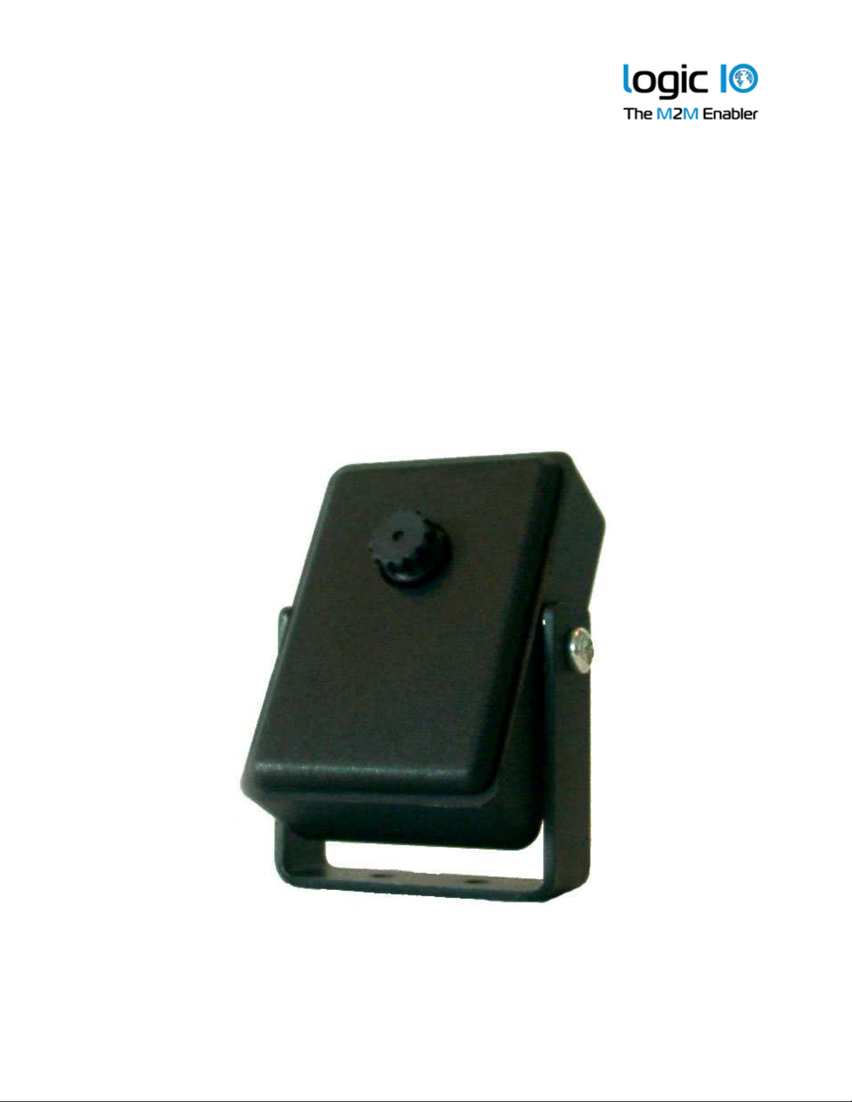
CAM-100
Technical Manual
Version 1.01
Page 2

CAM
-
100 – Technical Manual 1.0
1
Introduction
This manual contains technical documentation allowing easy installation and use of the
CAM-100 camera module designed for the RTCU X32 units. For information on the highlevel programming of the CAM-100, please refer to the RTCU IDE documentation.
The CAM-100 extends the capability of the RTCU platform with the ability to take JPEG
compressed snapshots. Snapshots can be taken in four different resolutions.
A whole new range of applications becomes available with CAM-100, such as:
• Remote monitoring of equipment, devices, work areas or locations.
• Any triggered event application.
• Security application.
• “A picture is worth a thousand words…”
Snapshots taken can either be saved to a SD-CARD, which can be accessed remotely, or
it can be sent directly over GPRS to a server.
Logic IO ApS. Ph: (+45) 7625 0210
Holmboes Allé 14 Fax: (+45) 7625 0211
8700 Horsens Email: [email protected]
Denmark www.logicio.com / www.rtcu.dk
Page 2 of 10
Page 3

CAM
-
100 – Technical Manual 1.0
1
Table of Contents
Introduction ..........................................................................................................................2
Table of Contents ................................................................................................................3
Graphical view .....................................................................................................................4
Installation............................................................................................................................5
MX2i Pro/Pro+ and DX4 Pro Connection .........................................................................5
AX9 Pro Connection.........................................................................................................5
Lens adjustment...............................................................................................................6
Bracket .............................................................................................................................7
Specifications.......................................................................................................................8
Appendix A ..........................................................................................................................9
Logic IO ApS. Ph: (+45) 7625 0210
Holmboes Allé 14 Fax: (+45) 7625 0211
8700 Horsens Email: [email protected]
Denmark www.logicio.com / www.rtcu.dk
Page 3 of 10
Page 4
CAM
-
100 – Technical Manual 1.0
1
Graphical view
Figure
1
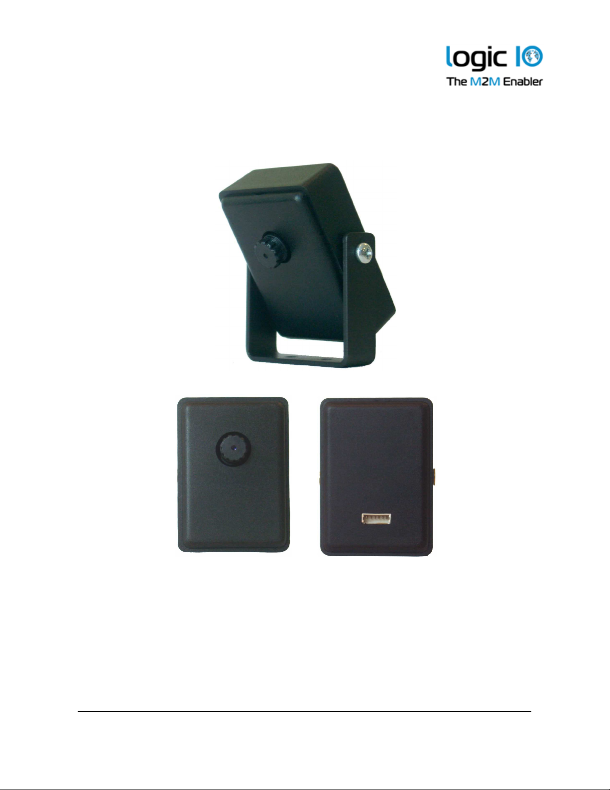
: Front and backside view
Logic IO ApS. Ph: (+45) 7625 0210
Holmboes Allé 14 Fax: (+45) 7625 0211
8700 Horsens Email: [email protected]
Denmark www.logicio.com / www.rtcu.dk
Page 4 of 10
Page 5
CAM
-
100 – Technical Manual 1.0
1
Installation
MX2i Pro/Pro+ and DX4 Pro Connection
The CAM-100 is connected to serial port 1 (service port) on the RTCU MX2/DX4. For this
purpose a 3 meter cable is delivered, which also allows placement of the CAM-100 away
from the RTCU X32 unit itself.
Power supply for the CAM-100 is controlled by the RTCU X32i. This keeps the power
consumption kept at a minimum, only turned on when taking snapshots.
AX9 Pro Connection
The CAM-100 is delivered with the same 3 meter cable as for MX2i and DX4, but there
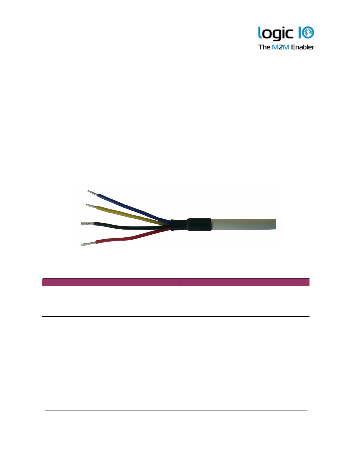
isn’t a 6-poled tyco connector for easy-to-plug. The color coded 4 cables need to be
connected to the AX9 manually. Cables are color coded, and these colors will be used in
the following description:
As seen on the above picture, there are 4 signals to be connected to the AX9 Pro. The
cable color and the signal name on the AX9 Pro is given in the following table:
Color Signal Name
Black SGND
Yellow SER1_RXD
Blue SER1_TXD
Red DCOUT33
Connect the 4 colored cables to their respective labeled angled screw terminals as
mentioned in the above table. Please refer to AX9 Pro Technical Manual to locate the
terminals.
Page 5 of 10
Logic IO ApS. Ph: (+45) 7625 0210
Holmboes Allé 14 Fax: (+45) 7625 0211
8700 Horsens Email: [email protected]
Denmark www.logicio.com / www.rtcu.dk
Page 6
CAM
-
100 – Technical Manual 1.0
1
Lens adjustment
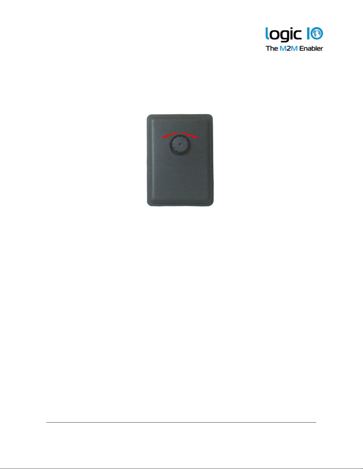
After the CAM-100 is placed correctly, the focus needs adjustment. This is done by turning
the lens carefully left or right manually, depending on the distance to the objective to focus
on.
Figure 2: Lens adjustment
Logic IO ApS. Ph: (+45) 7625 0210
Holmboes Allé 14 Fax: (+45) 7625 0211
8700 Horsens Email: [email protected]
Denmark www.logicio.com / www.rtcu.dk
Page 6 of 10
Page 7
CAM
-
100 – Technical Manual 1.0
1
Bracket
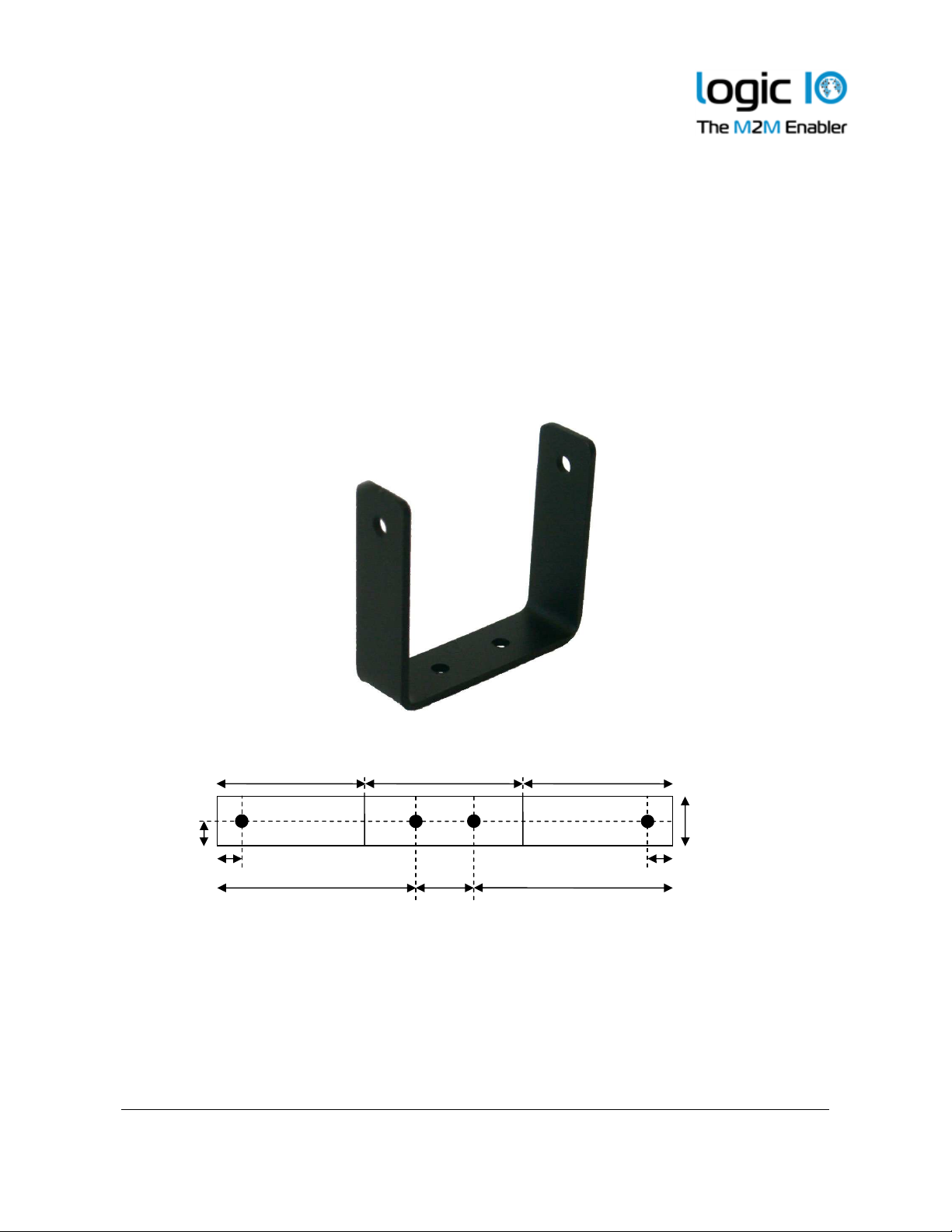
The combination of the bracket and the way the CAM-100 is fastened to the bracket
makes it possible to install the CAM-100 so that any angle can be achieved.
The metal bracket only requires two screws for mounting the CAM-100 on a wall, ceiling or
anywhere else the application requires.
When the bracket has been mounted in the correct place, place the CAM-100 and use the
two M3x6 screws to fasten the CAM-100.
Below, in Figure 3, the dimensions and guidelines of the bracket can be found.
Logic IO ApS. Ph: (+45) 7625 0210
Holmboes Allé 14 Fax: (+45) 7625 0211
8700 Horsens Email: [email protected]
Denmark www.logicio.com / www.rtcu.dk
6 mm
6 mm
Ø = 3mm
38 mm 36 mm 36 mm
12 mm
6 mm
48 mm 48 mm 14 mm
Figure 3: Bracket
Page 7 of 10
Page 8
CAM
-
100 – Technical Manual 1.0
1
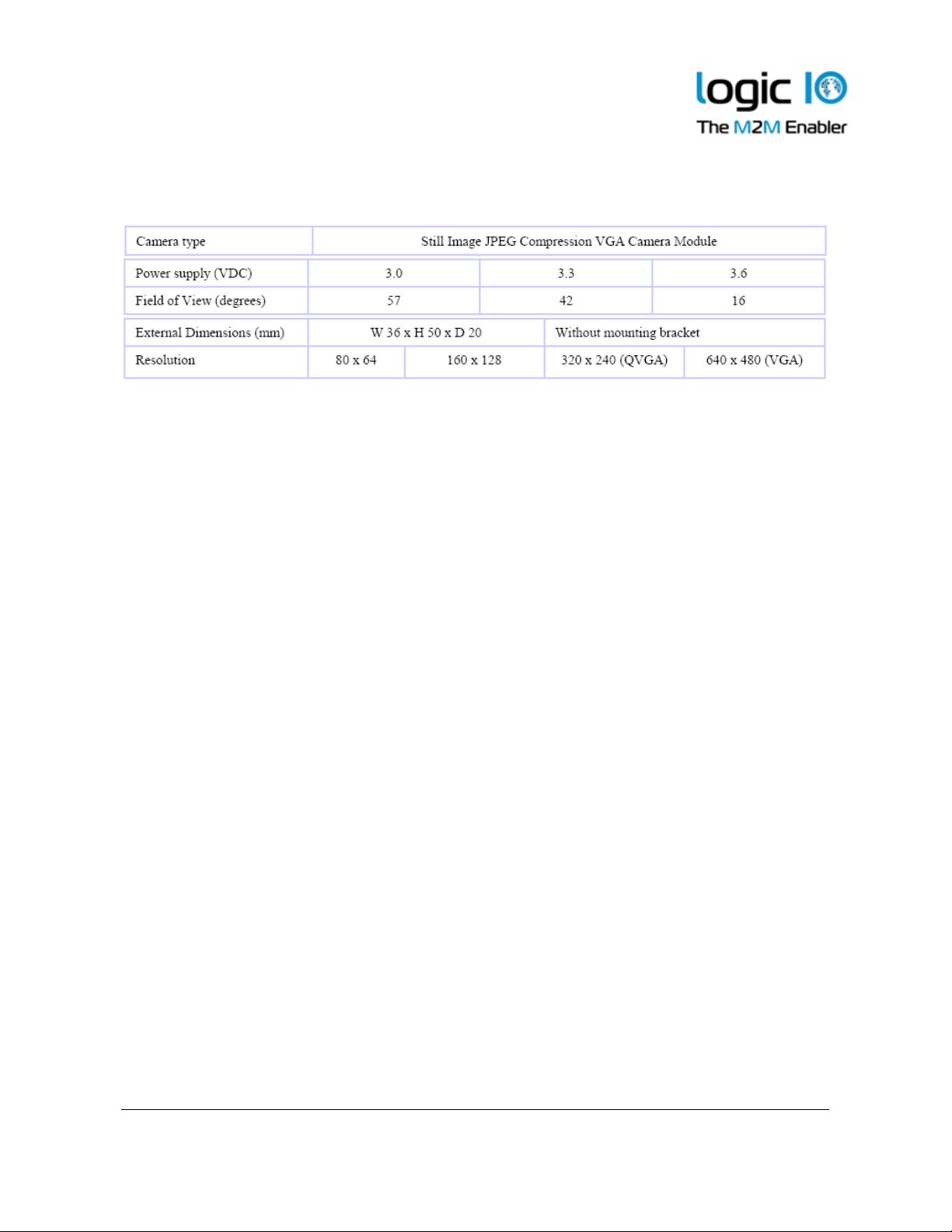
Specifications
Logic IO ApS. Ph: (+45) 7625 0210
Holmboes Allé 14 Fax: (+45) 7625 0211
8700 Horsens Email: [email protected]
Denmark www.logicio.com / www.rtcu.dk
Page 8 of 10
Page 9
CAM
-
100 – Technical Manual 1.0
1
Appendix A
Logic IO ApS. Ph: (+45) 7625 0210
Holmboes Allé 14 Fax: (+45) 7625 0211
8700 Horsens Email: [email protected]
Denmark www.logicio.com / www.rtcu.dk
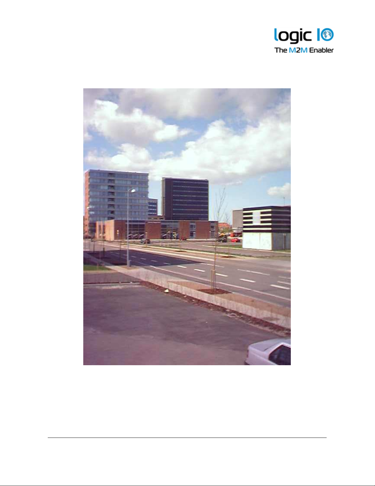
Figure 4: Area overview
Page 9 of 10
Page 10
CAM
-
100 – Technical Manual 1.0
1
Logic IO ApS. Ph: (+45) 7625 0210
Holmboes Allé 14 Fax: (+45) 7625 0211
8700 Horsens Email: [email protected]
Denmark www.logicio.com / www.rtcu.dk
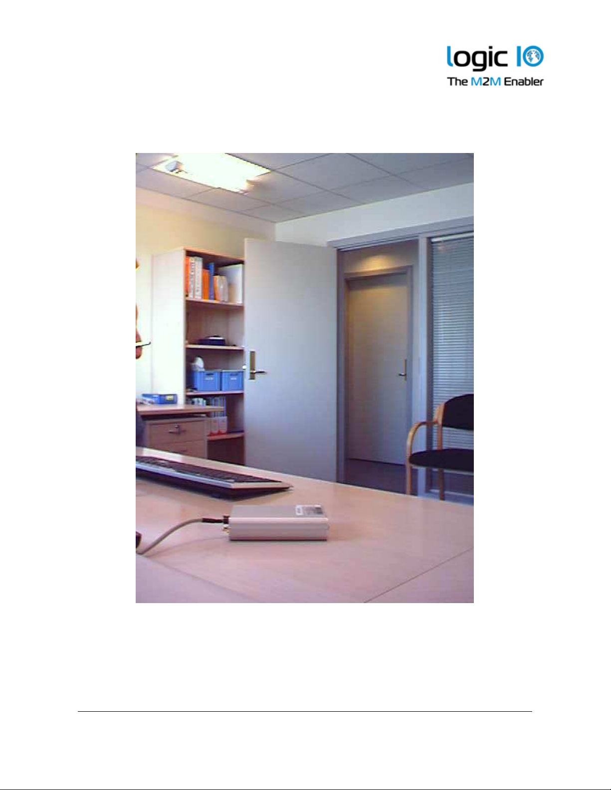
Figure 5: Room overview
Page 10 of 10
 Loading...