

Page 1

LGT8F328P
FEBRUARY 9, 2021
Ricky Gai
Revision 2.1
by
Nexuz Innovation, Malaysia.
( MA0255412-M )
Page 2

LGT8F328P rev 2.1 Page 1
Introduction
About this Book
This book is about hands-on information documented to illustrate the use of LGT8F328P chips that
tested and run successfully on Arduino sketch projects using Arduino C/C++ programming language.
In the learning of Arduino platform and compatible microcontrollers, there often lack of information,
incomplete online help comments, circuitry implemented may not be the same result as the original
circuit diagram and many different MCU libraries required to compile sketch, where can easily
forgotten.
Therefore, I decided to write this book to document steps that went through before and solutions
found. It is not perfect, but with necessary guidelines to get through and move on.
LGT8F328P LQFP32 and SSOP20 MiniEVB were adopted in this book as to facilitate the learning
process, and we do want to build something optimum at the end.
To understand this book, reader should be familiar with Arduino IDE, basic electronics fundamental,
PCB design and C/C++ software programming
About the Author
Ricky Gai
is the founder and technical director of Nexuz Innovation, a small R&D IT company established in
Kuala Lumpur, Malaysia.
After receiving certification from Oxford Computer Engineering discipline in 1992, my carreer was
mostly exposed to C/C++ system software development for decades about 30 years, since the MSDOS time until today’s Windows environments including real-time, networking, file system, 2D/3D
games, software driver, application and mobile programming.
Nevertheless, much spare time devoted to further the electronics studies for two years before coming
to Arduino platform, and my wife often staring at me. Arduino programming reminded me the MSDOS season, it brought back memory of something like interrupt, vector and bootsector ( eg.
Bootloader in Arduino ).
All the reference materials and source code are available via Github at:
https://github.com/rickygai/arduino
For any errors found, suggestions and questions, please do email to:
support@nexuzinnovation.com
Well, passion is everything and the key to success, I hope you find something useful here.
© All rights reserved, Nexuz Innovation. www.nexuzinnovation.com
Page 3

Abbrevation
Descriptions
NEXUZ INNOVATION / AUTHOR
refers to the author, Ricky Gai.
READER / READER(S) / READER’S
refers to the person who read or knowledge transferred, accessed the
circuitry setup based on the contents illustrated in this document.
COMPONENTS / EQUIPMENTS
refers to electronics components, tools, materials that used as part of the
circuitry setup.
CONTENTS
Information described within the document, including software and hardware
solutions or mathods described by the author.
IP / INTELLECTUAL PROPERTY /
COPYRIGHT / PERMISSION
refers to the copyrighted materials ( eg. Photo, Diagram, Source Code, Links )
that owned by other creators.
LGT8F328P rev 2.1 Page 2
DISCLAIMER
THIS CONTENTS OF THIS DOCUMENT IS SOLELY BASED ON THE ELECTRONICS COMPONENTS OR
MATERIALS ADOPTED AND TESTED BY AND AT THE AUTHOR’S PREMISES. DUE TO VOLTAGE
SUPPLY VARIES FROM DIFFERENT COUNTRIES AND PHYSICAL SPECIFICATION OF COMPONENTS
MAY CHANGE FROM TIME TO TIME, READER(S) TAKE OWN RESPONSIBILITY TO ACCESS THE
EXPERIMENTAL SOLUTIONS BASED ON THE INFORMATION DESCRIBED IN THIS DOCUMENT.
THE COMPANY NEXUZ INNOVATION AND THE AUTHOR BARES NO RESPONSIBILITY UPON ANY
DAMAGE OR HARM IN CASE HAPPENS TO THE READER(S) OR READER’S SIDE, THIS INCLUDE
READER’S RELATED SUCH AS HUMAN HEALTH, HARDWARE EQUIPMENTS AND OTHER LOSSES.
NEXUZ INNOVATION IS A SOLE PROPRIETORSHIP COMPANY WITH NO RELATION TO ANY
HARDWARE MANUFACTURERS OR VENDORS MENTIONED IN THIS DOCUMENT, SUCH AS LOGIC
GREEN, ARDUINO AND ETC. THE MENTIONED OF INTEGRATED CIRCUIT ( IC ) OR CHIPS PRODUCT
MODELS ARE SOLELY FOR RESEARCH AND DEVELOPMENT PURPOSES ONLY.
THE AUTHOR RESPECTS THE INTELLECTUAL PROPERTY FROM OTHER CREATORS, THIS
DOCUMENTATION MAY SHARE SOME PARTLY EXTRACTED PORTION OF PHOTO OR DIAGRAM AS
PART OF THE ILLUSTRATION USAGE. IF THERE IS ANY COPYRIGHT INFRINGEMENT, PLEASE DO
INFORM THE AUTHOR TO EXCLUDE FROM THIS DOCUMENT.
© All rights reserved, Nexuz Innovation. www.nexuzinnovation.com
Page 4

LGT8F328P rev 2.1 Page 3
Pinout Diagram
References
Figure 1: LGT8F328P LQFP32 MiniEVB board.
LGT8F328P is one of the Arduino
clone chip created by Logic Green.
Logic Green LGT8F328P datasheet
( in Chinese )
Logic Green official manuals
( datasheets, circuit pinout diagrams )
Ralph Bacon LGT8F328P-Arduino-Clone-ChipATMega328P
( with English version of LGT8F328P
datasheet )
Types of LGT8F328P chips
LGT8F328P LQFP32 MiniEVB
Physical Layout
© All rights reserved, Nexuz Innovation. www.nexuzinnovation.com
Page 5
LGT8F328P rev 2.1 Page 4
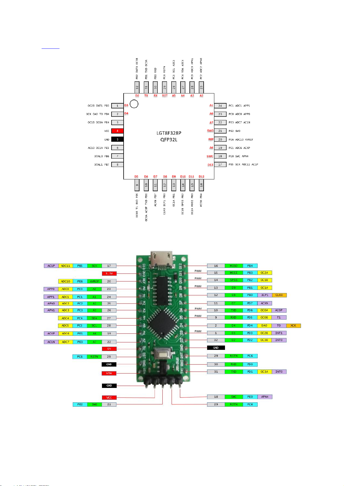
Pinout
Figure 2: LGT8F328P LQFP32 chip pinout.
Figure 3: LGT8F328P LQFP32 board pinout.
© All rights reserved, Nexuz Innovation. www.nexuzinnovation.com
Page 6

LGT8F328P rev 2.1 Page 5
Pinout Diagram
References
Figure 4: LGT8F328P SSOP MiniEVB board.
Same as above.
LGT8F328P SSOP20 MiniEVB
Physical Layout
© All rights reserved, Nexuz Innovation. www.nexuzinnovation.com
Page 7

LGT8F328P rev 2.1 Page 6
Pinout
Figure 5: LGT8F328P SSOP20 chip pinout.
Figure 6: LGT8F328P SSOP20 MiniEVB board pinout.
© All rights reserved, Nexuz Innovation. www.nexuzinnovation.com
Page 8

LGT8F328P rev 2.1 Page 7
Diagrams
Descriptions & References
It is very important to configure the installed LGT8F328P libraries as to appear
under the Arduino IDE menu outstandingly such as below:
Figure 7: Multiple LGT8F328P libraries installed with orgainized
Figure 8: The default attribute name=“Arduino AVR Boards”
Figure 9: The default attribute name=“Arduino AVR Boards”
There are many versions of LGT8F328P
libraries built by different authors. Here,
I choose to install three board libraries
from:
Logic Green
Ralph Bacon
David Buezas
To have a proper names listed as shown
on Figure 7, you have to edit the file
platform.txt from each of the author’s
library path installed, otherwise the listed
items under “Board Manager” will be
confusing such as below:
Arduino AVR Boards
Arduino AVR Boards
Logic Green Arduino AVR Compatible
Boards
Depends of which version of Arduino IDE
you are using, mine is 1.8.13 and it
duplicated the default name “Arduino
AVR Boards” because the platform.txt
bundled under Logic Green and Ralph
Bacon package file used the same
default attribute “name=Arduino AVR
Boards” as shown on Figure 8.
To solve this problem, I edited three of
the platform.txt files and renamed the
attribute “name=” of each file
respectively to something like below:
name=LGT8F328P - Logic Green
name=LGT8F328P - Ralph Bacon
name=LGT8F328P - David Buezas
To be more precisely, I renamed the
library folder for Ralph Bacon and David
Buezas as shown on Figure 9.
In my case, these three platform.txt files
are located under:
C:\arduino-
1.8.13\hardware\LGT\avr\platform.txt
C:\arduino-1.8.13\hardware\Ralph
Bacon\avr\platform.txt
C:\arduino-1.8.13\hardware\David
Buezas\avr\platform.txt
The path locations above may be
different, subjected to individuals’
Arduino IDE installation.
Prerequisition
Arduino IDE - Setup the LGT8F328P library
Download, install and configure the LGT8F328P libraries
© All rights reserved, Nexuz Innovation. www.nexuzinnovation.com
Page 9
LGT8F328P rev 2.1 Page 8
Diagrams
Descriptions & References
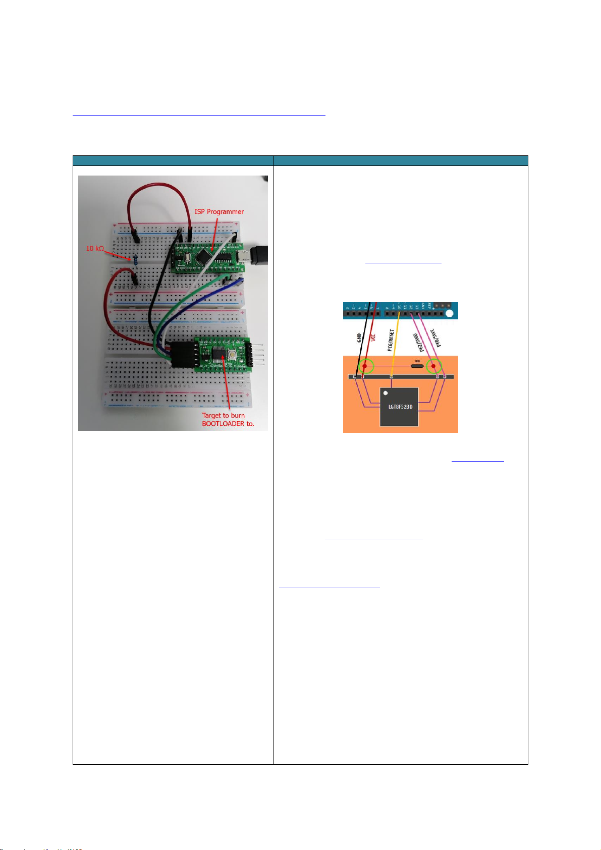
Figure 10: LarduinoISP working circuitry setup
LarduinoISP is the use of Arduino ATMega328P ( eg. NANO, UNO )
or LGT8F328P ( LQFP32 MiniEVB ) as ISP Programmer to burn
BOOTLOADER to the Target LGT8F328P SSOP20 MiniEVB as shown
at Figure 10.
Here, I want to share some painful experiences that went through
in dealing with the LarduinoISP circuitry setup.
I started by referring to LGTMCU/LarduinoISP, at that time I was
doubted about the short-circuit of the 10kΩ resistor between VCC
and SWD pin as shown at Figure 11, with two green highlighted
circles below:
Figure 11: LGT/LarduinoISP extracted diagram
Really wasted much time on it, no one from the Arduino Forum can
gives me at least a snapshot photo of how to setup the physical
circuitry correctly.
Based on Figure 10, I decided to remove the SWD ( blue wire )
from connecting to the 10kΩ pull-up resistor and connect directly to
pin 12 of the ISP Programmer.
Next, I used David Buezas’s LarduinoISP sketch to upload to the
ISP Programmer because his sketch is more recently updated.
Somehow, still failed to upload the sketch ( may be that time
Arduino Nano was used as ISP Programmer ). Later, a site called
SuperUserNameMan/LGTISP, after reading its usage section, I
begin to realize the whole story and quickly edit the
HardwareSerial.h to to change the following instruction from:
#define SERIAL_RX_BUFFER_SIZE 64
to:
#define SERIAL_RX_BUFFER_SIZE 250
Eventually, LarduinoISP successfully burned the BOOTLOADER to
the Target LGT8F328P SSOP20 MiniEVB.
The entire circuitry is very straight forward actually but took me
sometime to accomplish.
NOTE: Remember to set back 64 to SERIAL_RX_BUFFER_SIZE as it
may affect some other libraries.
Arduino Sketch Projects
LarduinoISP - How to burn the BOOTLOADER ?
Introduction
© All rights reserved, Nexuz Innovation. www.nexuzinnovation.com
Page 10

LGT8F328P rev 2.1 Page 9
Components
Quantity
LGT8F328P LQFP32 MiniEVB
1
LGT8F328P SSOP20 MiniEVB
1
FTDI FT232RL
1
RESISTOR 10kΩ
1
10 cm Female-to-Male Jumper Wire
5
10 cm Female-to-Female Jumper Wire
5
10 cm Male-to-Male Jumper Wire
1
USB 2.0 Micro B cable connector
1
USB 2.0 Mini B cable connector
1
MB102 Mini Breadboard 8.5CM x 5.5CM 400 Holes
2
Illustrations
Descriptions
1. First, you have to complete the Prerequisition stage. For
illustration purposes, we adopted David Buezas LGT8FX board
library.
2. After you have completed step 1, put the LGT8F328P LQFP32
MiniEVB on the breadboard then connect the USB Micro B cable as
shown on Figure 12 to the PC.
Figure 12: LGT8F328P LQFP32 MiniEVB on
empty breadboard
Illustrations
Descriptions
3. At the Arduino IDE, File Examples LarduinoISP
LarduinoISP, click on it to open such as Figure 13.
Figure 13: Opening the LarduinoISP sketch
4. Next, turn ON the LGT8F328P LQFP32 MiniEVB, the respective
serial port should be detected, in this case it is COM19 under the
Windows Device Manager at Figure 15.
5. Goto the File menu, Tools Port: select COM19 as shown
below:
Figure 14: Selecting the LGT8F328P LQFP32 Serial Port
Figure 15: LGT8F328P LQFP32 Serial Port
under Device Manager
The Parts list
Installing the LGT8F328P board library
Opening the LarduinoISP sketch
© All rights reserved, Nexuz Innovation. www.nexuzinnovation.com
Page 11

Illustrations
Descriptions and Fundamental Units
6. Open the file HardwareSerial.H using
Notepad:
C:/arduino-
1.8.13/hardware/arduino/avr/cores/arduino/HardwareSerial.h
7. Change “#define SERIAL_RX_BUFFER_SIZE
64" to “#define SERIAL_RX_BUFFER_SIZE
250" as shown on Figure 16.
8. Save the file.
Figure 16: HardwareSerial.H updates
Illustrations
Descriptions and Fundamental Units
9. Goto File menu, Tools Board:
LGT8F328P - David Buezas select
LGT8F328 as shown on Figure 17.
Figure 17: Selecting David Buezas LGT8F328 board library
10. Make sure under the Tools menu options,
all settings are based on Figure 18.
11. Upload the sketch by clicking
button.
Figure 18: David Buezas LGT8F328 settings
LGT8F328P rev 2.1 Page 10
Updating HardwareSerial.H
Uploading LarduinoISP sketch to ISP Programmer ( LGT8F328P LGFP32 MiniEVB )
© All rights reserved, Nexuz Innovation. www.nexuzinnovation.com
Page 12

Descriptions
12. If the LarduinoISP sketch is successfully uploaded to ISP Programmer ( LGT8F328P LQFP32 MiniEVB ), you should
be seeing messages below:
Figure 19: The success messages of LarduinoISP sketch uploaded to ISP Programmer
Illustrations
Descriptions
13. Now, the ISP Programmer is ready.
14. Turn off the ISP Programmer.
15. We are going to wire up the LarduinoISP circuitry just
like Figure 21.
16. LarduinoISP wire connection table:
Figure 20: LarduinoISP wire connection
Figure 21: LarduinoISP circuitry setup
LGT8F328P rev 2.1 Page 11
The success messages of LarduinoISP sketch uploaded to ISP Programmer.
Wiring up the LarduinoISP circuitry
© All rights reserved, Nexuz Innovation. www.nexuzinnovation.com
Page 13

Illustrations
Descriptions
17. We are now going to burn the BOOTLOADER to the
Target LGT8F328P SSOP20 MiniEVB.
18. Turn on the ISP Programmer.
19. At the File menu, Tools Variant: select “328P-
SSOP20 (e.g. green pseudo pro mini)” as shown on
Figure 22.
20. Ignore the “Arduino as ISP”, select Programmer as
“AVR ISP”.
21. Click on the “Burn Bootloader”.
Figure 22: Change the Variant to Target LGT8F328P
SSOP20
Figure 23: To Burn Bootloader
Descriptions
22. If the BOOTLOADER is successful, you will see the message below:
Figure 24: The success messages of burning BOOTLOADER to Target LGT8F328P SSOP20 MiniEVB
LGT8F328P rev 2.1 Page 12
To burn BOOTLOADER to Target LGT8F328P SSOP20 MiniEVB
The success messages of burning the BOOTLOADER to the Target.
© All rights reserved, Nexuz Innovation. www.nexuzinnovation.com
Page 14

Illustrations
Descriptions and Fundamental Units
23. Congratulations, the Target LGT8F328P SSOP20
MiniEVB is burned with new BOOTLOADER image.
24. Here, we are going to do a test on it by uploading a
fast blinking sketch to see the significant changing
effects. If it is uploaded successfully, the LGT8F328P
SSOP20 MiniEVB should be blinking faster at 64 ms
interval.
25. Turn off the ISP Programmer, connect the
LGT8F328P SSOP20 MiniEVB to FTDI FT232RL as
shown on Figure 26.
26. The FTDI FT232RL connection, its CTS pin is not
required here:
Figure 25: The standalone LGT8F328P SSOP20 MiniEVB pin
connection with FTDI FT232RL
27. Turn on the FTDI FT232RL that will power up
LGT8F328P SSOP20 MiniEVB.
28. NOTE: This will create a new serial port COM22
interface as shown on Figure 27.
Figure 26: The standalone LGT8F328P SSOP20 MiniEVB
with FTDI FT232RL interface
Figure 27: FTDI FT232RL new serial port interface
29. Take a look at the LGT8F328P SSOP20 MiniEVB by
default itself, it is blinking at internal roughly two
seconds as shown on Figure 28.
To see the different, later when the new sketch
blink64ms.ino is uploaded to it, the blue LED should
be blinking faster at 64 ms interval.
Figure 28: FTDI FT232RL default blinking ( blue light )
two seconds interval
LGT8F328P rev 2.1 Page 13
Testing the LGT8F328P SSOP20 MiniEVB with new BOOTLOADER burned.
© All rights reserved, Nexuz Innovation. www.nexuzinnovation.com
Page 15

Descriptions
30. Here, we are to upload a sketch called blink64ms.ino to the LGT8F328P SSOP20 MiniEVB since the Bootloader
already written, if it is working normally after a reset, the Bootloader should starts and jumps to the program
address where the blink64ms.ino program will be loaded and run.
31. Select the correct Port COM22 ( FT232RL ) from the menu as shown below:
Figure 29: Selecting the FTDI FT232RL serial port COM22
32. At Arduino IDE, open the blink64ms.ino sketch then click the button to upload sketch.
33. If it is uploaded successfully you will notice the blue LED will blink faster continuously.
Descriptions and Fundamental Units
34. The success messages after blink64ms.ino sketch uploaded to LGT8F328P SSOP20 MiniEVB will look like below:
Figure 30: The success messages of uploading blink64ms.ino sketch to LGT8F328P SSOP20 MiniEVB
35. DONE.
LGT8F328P rev 2.1 Page 14
Uploading blink64ms.ino sketch to LGT8F328P SSOP20 MiniEVB via FT232RL
The success messages of uploading blink64ms.ino to LGT8F328 SSOP20 MiniEVB
© All rights reserved, Nexuz Innovation. www.nexuzinnovation.com
 Loading...