

Page 1
Logic Digital Crossover
logic system
DP2140-2160 User Guide
R3-(08/03/2010)
Page 2
Logic Digital Controller
User Guide version 3 Page 2 of 31
Quick Reference Guide
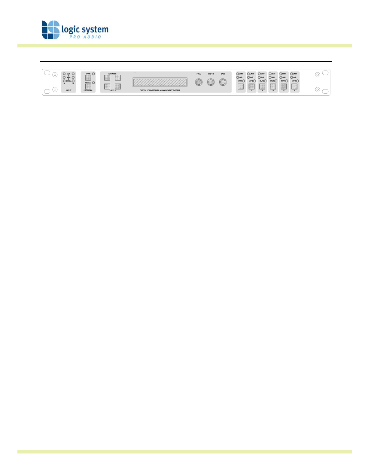
Display
The LCD displays preset and parameter information. The default screen is shown after start up and
displays the number and name of the current preset on the lower line of text. When navigating around
the adjustable parameters, other information is shown.
Channel Select Buttons
The currently selected input or output channel is shown in the top left corner of the display. Pressing the
channel select buttons scrolls through the available inputs and outputs. If operating stere o linke d the
channel pair is shown. For example ‘CH A+B’ means both input A and B parameters.
Edit Select Buttons
The name of the edit parameter page is displayed in the bottom left portion of the LCD. Pressing the edit
select buttons moves through the available parameter pages for the current input or output.
Parameter Knobs
Up to three parameters are shown on the display. The parameter name is shown with its’ current value
below. Where appropriate, parameters are grouped according to function. For example the parametric
equalisation page shows centre frequency, width and gain. Turning a parameter knob clockwise will
increase the value of a parameter, turning anti-clockwise will decrease it. Turning a knob rapidly will
cause the action to ‘accelerate’, so the value changes more rapidly.
Mute Buttons
The LEDs next to the mute buttons indicate their current status. Pressing a mute button toggles between
the mute on and off.
Store Button
The unit has 45 preset locations. To store a preset in a location, press the store button and use the
parameter knobs to select the preset location and name the preset. Pressing the store button again
completes the task. Pressing any button other than store during the process cancels the procedure.
Recall Button
To recall a preset, press the recall button and use parameter knob A to select the required preset.
Pressing the recall button again will activate the preset. You will then be asked to confirm by pressing
recall once more. As with the store function, pressing any button other will cancel the process.
Page 3

Logic Digital Controller
User Guide version 3 Page 3 of 31
Quick Reference Guide .......................................................................................................................2
Display.......................................................................................................................................2
Channel Select Buttons................................................................................................................2
Edit Select Buttons......................................................................................................................2
Parameter Knobs ........................................................................................................................2
Mute Buttons..............................................................................................................................2
Store Button...............................................................................................................................2
Recall Button ..............................................................................................................................2
Important Safety Information..............................................................................................................5
Regulatory Compliance................................................................................................................5
Thanks and Unpacking .......................................................................................................................6
Introduction and Key Features ............................................................................................................7
Introduction................................................................................................................................7
The User Guide..................................................................................................................................8
Front Panel........................................................................................................................................9
Input Signal Indicators ................................................................................................................9
Preset Store and Recall ...............................................................................................................9
Channel Select Buttons................................................................................................................9
Edit Select Buttons....................................................................................................................10
Text Display..............................................................................................................................10
Parameter Knobs ......................................................................................................................10
Output Signal / Limiter Indication...............................................................................................10
Mute Buttons and Status LEDs...................................................................................................10
Secure Button (on the rear).......................................................................................................11
Rear Panel.......................................................................................................................................11
Power Inlet...............................................................................................................................11
Network Expansion Port ............................................................................................................11
Audio Input Connectors.............................................................................................................11
Audio Output Connectors...........................................................................................................12
Communications Port Connector ................................................................................................12
Operation ........................................................................................................................................13
Starting up ...............................................................................................................................13
Selecting a Factory Preset .........................................................................................................13
Creating a Crossover.................................................................................................................13
Navigation and Viewing Parameters ...........................................................................................14
Navigation................................................................................................................................14
Presets.....................................................................................................................................15
Preset Recall.............................................................................................................................15
Preset Store..............................................................................................................................16
DSP Processing layout ......................................................................................................................18
Input DSP block diagram...........................................................................................................18
Output DSP block diagram.........................................................................................................18
Page 4

Logic Digital Controller
User Guide version 3 Page 4 of 31
Stereo / Mono Formats..............................................................................................................18
DSP processing.........................................................................................................................19
Input Channels .........................................................................................................................19
Output Channels.......................................................................................................................21
Utilities............................................................................................................................................25
Factory Presets................................................................................................................................26
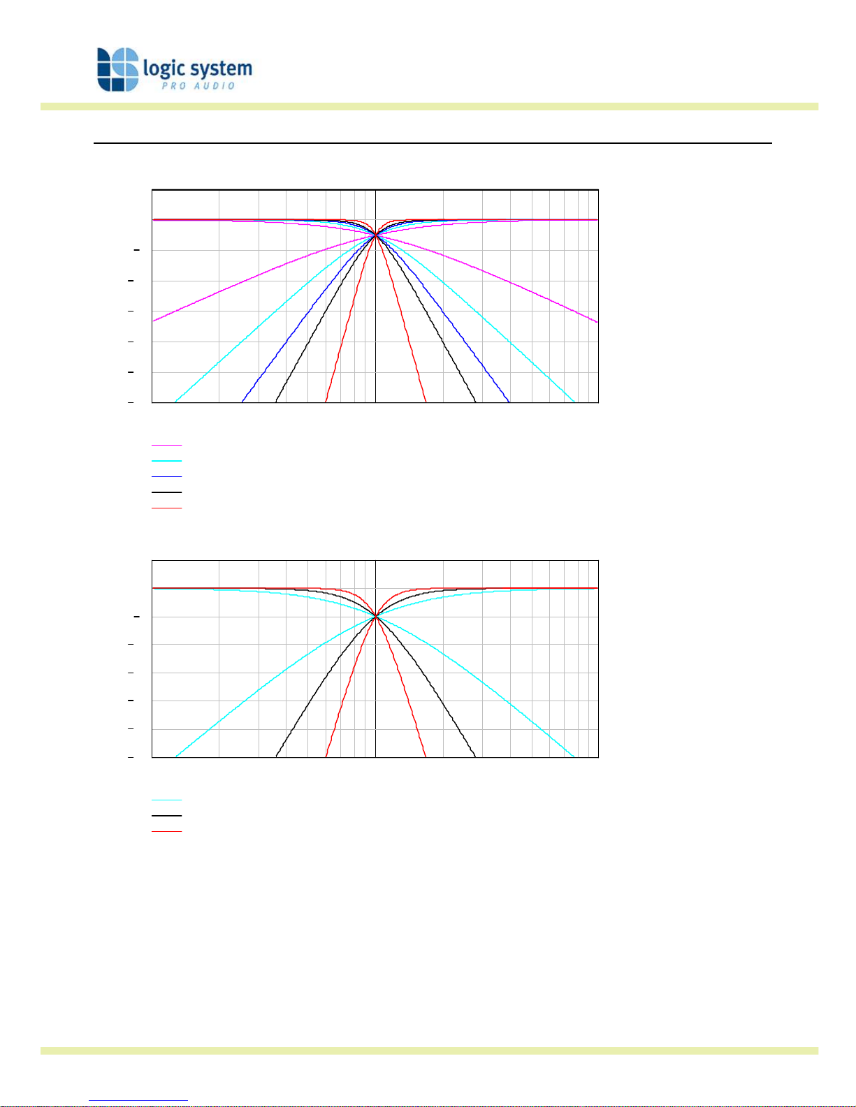
EQ and Filter Response Graphs .........................................................................................................27
Technical Specification......................................................................................................................30
General ....................................................................................................................................30
Processing................................................................................................................................30
Connectors...............................................................................................................................30
Page 5

Logic Digital Controller
User Guide version 3 Page 5 of 31
Important Safety Information
Please read carefully and keep the following instructions and safety information. Heed all
warnings and follow all instructions.
• Do not remove covers. There are no user serviceable parts inside, please refer
servicing to qualified service personnel.
• This equipment must be earthed.
• Protect the power cord from being walked on or pinched particularly at plugs,
convenience receptacles, and the point where they exit from the apparatus.
• Only use attachments/accessories specified by the manufacturer.
• Servicing is required when the apparatus has been damaged in any way, such as the
power supply cord or plug is damaged, liquid has been spilled or objects have fallen into
the apparatus, the apparatus has been exposed to rain or moisture, does not operate
normally, or has been dropped.
Regulatory Compliance
This product complies with both the EMC Directive (89/336/EEC) and the Low Voltage Directive
(73/23/EEC) as issued by the Commission of the European Community.
Compliance with these directives implies conformity with the following European standards:
• EN60065 Product safety
• EN55103-1 Electromagnetic Interference (Emission)
• EN55103-2 Electromagnetic Susceptibility (Immunity)
This product is intended for operation in the E2 (commercial & light industrial) and E3 (urban
outdoors) Electromagnetic Environments.
Page 6

Logic Digital Controller
User Guide version 3 Page 6 of 31
Thanks and Unpacking
Thank you for choosing a Logic System Digital series loudspeaker management system for your
application. Please spare a little time to study the contents of this manual, so that you obtain
the best possible performance from this unit.
All Logic System products are carefully engineered for world-class performance and reliability. If
you would like further information about this or any other Logic System product, please contact
us. We look forward to helping you in th e near future.
Unpacking the LOGIC SYSTEM Digital series processor
After unpacking the unit please check carefully for damage. If damage is found, please notify
the carrier concerned at once. You, the consignee, must instigate any claim. Please retain all
packaging in case of future re-shipment.
Page 7

Logic Digital Controller
User Guide version 3 Page 7 of 31
Introduction and Key Features
Introduction
The LOGIC SYSTEM Digital series of loudspeaker management systems represent the current
state-of-the-art. Taking advantages of the latest advances in analogue to digital conversion and
digital signal processing technologies the units achieve performance levels that have only
recently been made possible.
Key Features
• Linea Research minimal signal path design
• Sonically superb ADC / DAC combination; a carefully matched pairing of the best devices
from Burr Brown and Wolfson
• Newly released family of Analogue Devices SHARC DSP
• Extended bandwidth; 96 kHz sampling frequency provides for a nominally flat response to
40 kHz.
• Parameter knob and LCD provide a rapid, user-friendly control interface
• Networking capability to control multiple units via the Bv Net protocol.
• Remote control of all functions via the ‘Podware’ software package.
Note
This manual is generic to 2 in 4 out and 2 in 6 out versions of the DP controller.
Page 8

Logic Digital Controller
User Guide version 3 Page 8 of 31
The User Guide
This user manual gives a progressively more detailed description of the functions of the LOGIC
SYSTEM Digital series loudspeaker management systems. A single page quick reference guide is
provided for those users who are experienced with this type of equipment and just need to
know how to ‘drive’ the front panel.
A detailed explanation of the front and rear panel controls and indicators is contained in the
next section. The final section describes each individual function or feature with annotated
images explaining its’ use. Where appropriate, the LCD is shown to further elaborate on the
units’ operation.
To complete the manual a reference section is included, describing the technical performance of
the device complete with graphs of filter responses and details of the Factory Presets and their
configuration.
Page 9
Logic Digital Controller
User Guide version 3 Page 9 of 31
Front Panel
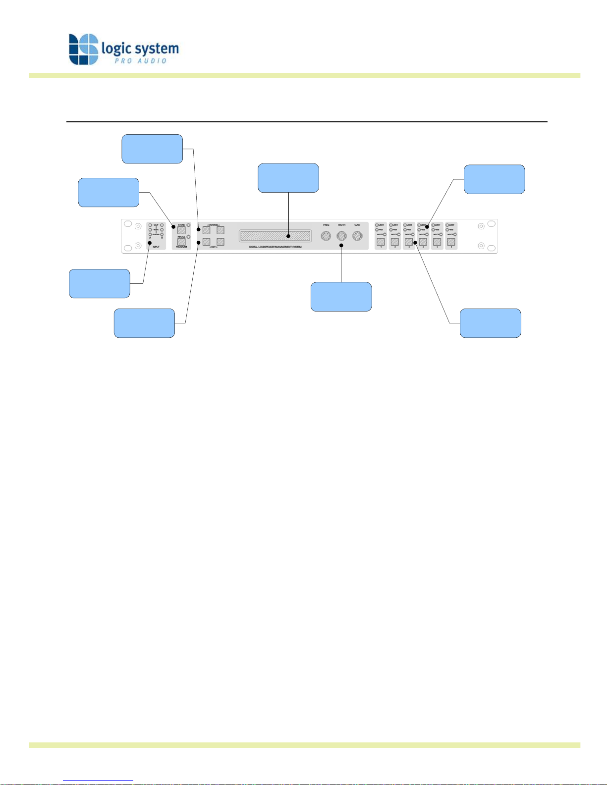
2x 24 character
LCD
Input Signal
Indicators
Store and
Recall buttons
Channel Select
buttons
Parameter Edit
Encoders
Output Mute
buttons
Limiter
Indicators
Edit Parameter
Select buttons
Input Signal Indicators
A set of three pairs of LEDs indicate signal present, +4dBu and input clip for each channel. The
signal present LEDs operate at approximately –40 dBu, giving a useful indication of even
relatively low input signal levels. The +4 dBu LEDs are intended to show nominal operating level
and can also be useful for setting system gain structure. Clip LEDs warn the user of input
overload and operate at +19 dBu.
Preset Store and Recall
These controls provide access to the 45 presets stored within the device. Pressing the store
button allows the user to name a preset and choose which memory location it will be held in.
Pressing store button again completes the process. The Recall function operates in a similar
way, pressing the recall button allows the user to select which preset they require, pressing the
button for a second time, then confirming, recalls the new DSP settings.
Note that presets cannot be stored or recalled when secure mode is activated.
Channel Select Buttons
The currently selected channel is displayed on the top left hand corner of the LCD. Pressing the
channel buttons scrolls through the available input and output channels and finally through the
utility functions and back to the default screen. If operating a stereo linked preset, the channel
Page 10

Logic Digital Controller
User Guide version 3 Page 10 of 31
name will indicate the channel pairing. For example ‘A+B’ means both input A and B
parameters. The name of the output will be shown briefly at the top of the display when
stepping onto an output.
Edit Select Buttons
The currently selected edit parameter page is displayed on the bottom left corner of the LCD.
Pressing the edit select buttons moves through the available parameters for the current input or
output.
Text Display
Preset, channel, parameter and status information is shown on the 2x 24-character text display.
In most screens the currently selected channel is displayed on the upper line and the edit
parameter on the lower line. To simplify the display and enhance security, some parameters or
parameter pages are omitted when not relevant.
Parameter Knobs
Three velocity sensitive parameter knobs are used to adjust parameters shown on the display.
Up to three parameters at a time are displayed on the screen. The parameter name is shown
above the parameter value in each of the three screen sections. The parameter knobs have a
fixed association with the screen sections; the rightmost parameter knob adjusts the rightmost
parameter and so on.
Output Signal / Limiter Indication
Two LEDs are provided for each output channel. These show the signal level relative to the
limiter threshold. The yellow LED will light when the signal is 6dB below the threshold and the
red warning LED will light when the limiter threshold is reached.
Mute Buttons and Status LEDs
Each output has a mute button and associated mute status LED. Pressing the button toggles the
mute on and off.
Note that the mute buttons do not function when the secure mode is activated.
Page 11
Logic Digital Controller
User Guide version 3 Page 11 of 31
Secure Button (on the rear)
A momentary button is fitted behind the rear panel, between the output XLRs and the RS232
port. When activated, this will disable all the front panel controls so they cannot affect the signal
path, making the unit secure against tampering. When in secure mode, the indicators still
operate normally. Note that the communications port is still active in secure mode.
Rear Panel
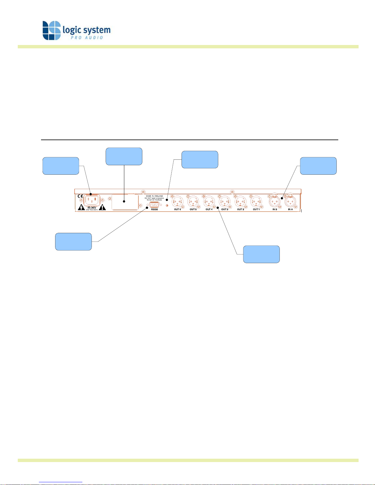
Power Inlet
Audio Output
Connectors
Serial Comms
Port
Audio Input
Connectors
Secure Mode
Switch
Expansion
Port
Power Inlet
The LOGIC SYSTEM Digital series unit should be connected to a suitable mains electricity supply
using the cable supplied. The processor has a switch mode power supply that is capable of
operating with a nominal mains voltage of 85V to 240V, 50/60Hz without re-configuration.
Network Expansion Port
Where a future network card can be fitted.
Audio Input Connectors
All audio connections are fully balanced and wired pin-1 ground, pin-2 hot & pin-3 cold. The two
inputs have pin-1 connected directly to the chassis and feed the signal processing chains. If an
unbalanced source is used, a connection should be made between the pin-3 ‘cold’ signal and the
ground connection of the unbalanced source.
Page 12

Logic Digital Controller
User Guide version 3 Page 12 of 31
Audio Output Connectors
The processed outputs are impedance balanced, and wired pin-1 ground, pin-2 hot and pin-3
cold. An unbalanced input may be driven by connecting pin-3 ‘cold’ signal to the ground
connection of the unbalanced destination input. Note that output pin-1’s are ground lifted at
audio frequencies but connected to ground at RF for good EMC performance. The intention
being that the amplifiers the processor is driving should be responsible for the grounding of
their input cable shields.
Communications Port Connector
Logic System Digital series processor may be controlled entirely from another controller,
typically a Personal Computer, running an application that is compliant with the ObCom
standard. Connection will normally be made to the controller via this serial port connector. This
port is also used for updating the firmware in the unit.
Note that the communications port is NOT disabled when the front panel is made secure using
the secure button.
Page 13

Logic Digital Controller
User Guide version 3 Page 13 of 31
Operation
Starting up
The unit will energise as soon as power is applied to the IEC inlet; there is no power switch.
During the start up process the firmware application model number and version numbers are
displayed and the outputs are muted until the unit has completed its internal checks. Once the
start-up routines are complete and the unit is ready to pass audio. The DSP signal path will be
restored to the current settings when it was last powered down and the audio signal is gradually
ramped up to its correct level.
Selecting a Factory Preset
The LOGIC SYSTEM Digital series processors have a library of Factory Presets designed to suit a
range of applications.
Factory Presets contain some parameters that are fixed and hidden from view; the remainder of
the DSP parameters are available for user manipulation. The number and type of hidden
parameters is dependant on the Factory Preset, typically crossover frequencies, output delay
and some EQ’s are hidden; those settings that are a function of the loudspeaker cabinet design
and should not require adjustment for different applications.
To recall a Factory Preset for a particular cabinet or system, press Recall and use the left hand
parameter knob A to scroll through the available Factory Preset locations (as indicated by a box
symbol after the preset number). Once the appropriate preset has been selected press recall
again, at which point you will be asked to confirm the action by pressing recall for a third time.
This is to guard against accidental recall of presets.
Factory Presets are locked so they cannot be over-written. The user can, however, store an
edited version of a Factory Preset in any free preset location.
Details of all the Factory Presets including output designations can be found in Appendix A.
Creating a Crossover
In addition to the Factory Presets the unit has two further ‘
Base Presets
’; mono and stereo.
These
Base Presets
are stored in locations 1 and 2 respectively, they can be used to develop
settings for any loudspeaker combination and are recalled in the same way as the Factory
Page 14
Logic Digital Controller
User Guide version 3 Page 14 of 31
Presets described above. These presets are also locked but the user can name and store their
own edited versions in any free preset location.
Navigation and Viewing Parameters
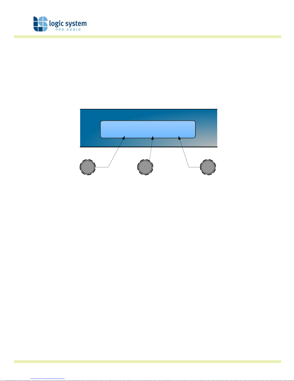
Many of the processing elements in each input and output path have features that may be
controlled by the user, such as gain, frequency or limiter threshold. We call these adjustable
features parameters.
In A Freq Width Gain
EQ1 100Hz 1.4Q 0.0dB
a
b
c
a b c
A parameter may be adjusted when it is displayed by turning one of the three-parameter knobs.
Each of the three-parameter knobs is associated with a zone on the display. Adjusting the
leftmost parameter knob will change the value of the parameter showing in the leftmost zone of
the display and so on. Turn a knob clockwise to increase the value of a parameter, or anticlockwise to decrease it. The knobs are velocity-sensitive so turning a knob rapidly will cause
the action to ‘accelerate’, so the value changes more rapidly.
Navigation
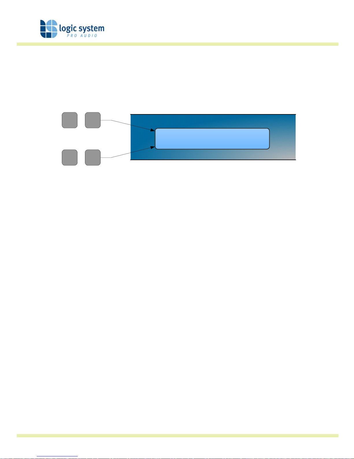
The DSP parameters are organised by channel. The currently selected channel is shown in the
top left hand corner of the display. You can navigate between the channels by pressing the
channel buttons. Pressing the channel buttons will scroll through the channels, utilities and back
to the default screen. When using a Preset that is stereo linked, the channel selection will reflect
this. For example ‘1&4’ indicates outputs 1 and 4. When navigating onto an output channel, the
usage of the output, as define in the Factory Preset, will be shown briefly at the top of the
screen.
Page 15
Logic Digital Controller
User Guide version 3 Page 15 of 31
Out1 Freq Width Gain
EQ1 100Hz 1.4Q 0.0dB
a
b
c
CHANNEL
EDIT
Pressing the edit navigation buttons gives access to the various pages of parameters available
for each channel. The currently selected page is shown in the bottom left hand corner of the
display; this is omitted on some pages where the function is obvious. The screen shows up to
three (normally related) parameters for a given part of the processing functions on a given
channel.
The edit buttons allow you to scroll, in either direction, through the different processing pages
for a given Channel. When you go past the last page, you will be returned to the default page.
The channel buttons allow you to scroll, in either direction, through the input and output
channels, whilst trying to maintain the currently viewed processing block. If the channel you
scroll to does not have the currently viewed processing block, the next one will be shown
instead.
NB. When the unit powers-up, the settings will be the same as those when the unit was last
switched off.
Presets
The device contains a total of forty-five user and Factory Presets. The user cannot overwrite the
basic mono, basic stereo or Factory Preset programs.
Preset Recall
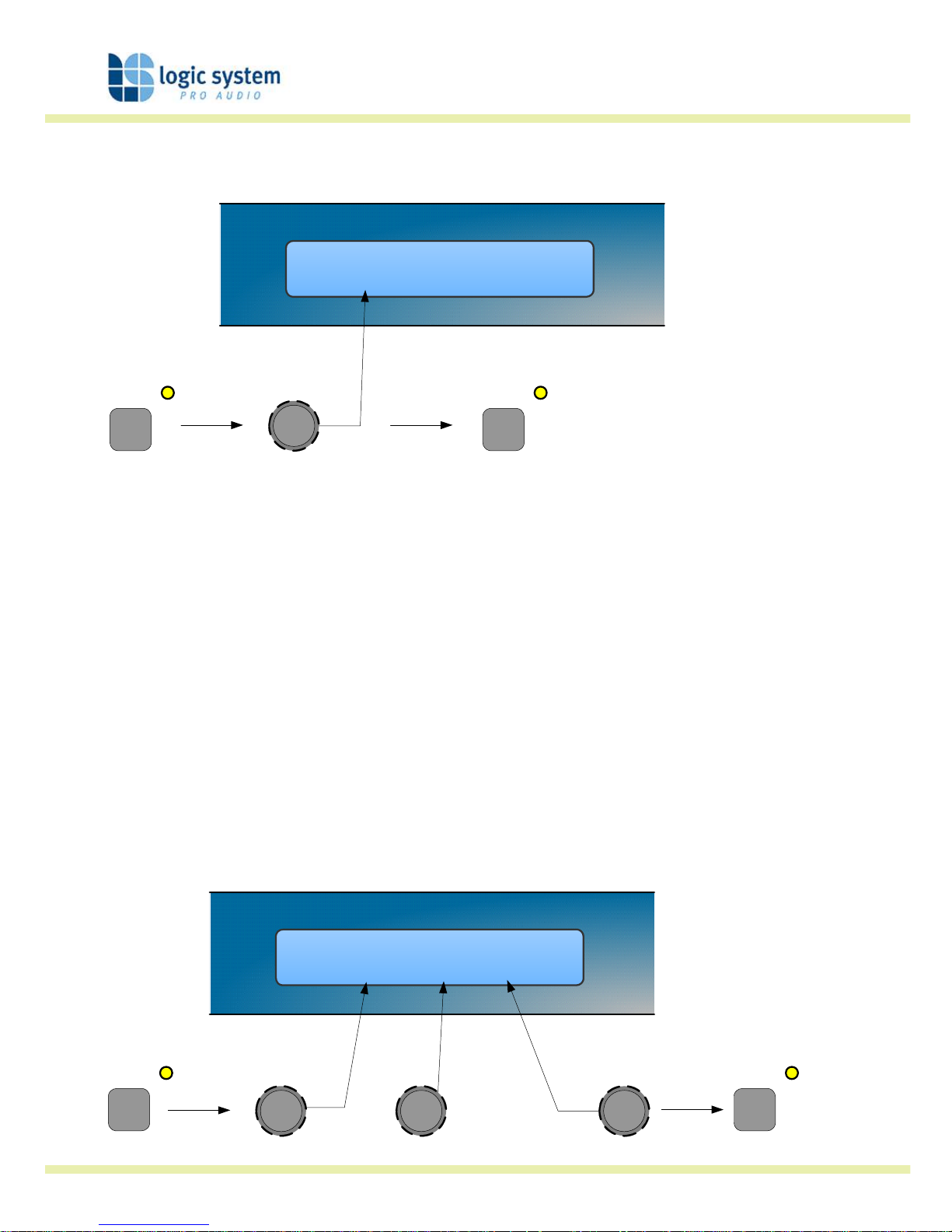
To select an existing preset, press the Recall Button so the indicator above it illuminates. Turn
parameter knob A until the required preset number is shown on the display. Factory Presets are
Page 16
Logic Digital Controller
User Guide version 3 Page 16 of 31
indicated by a box symbol appearing after the preset number. Press the Recall Button again to
activate the Preset. Pressing any other button will cancel the operation.
Preset Name
Recall 32 My System
ab
c
SELECT PRESET
TO RECALL
a
RECALL RECALL
Users can develop their own Preset based on one of the Basic or Factory Presets stored within
the device. Once a basic or user Preset has been recalled, a user has complete freedom to
adjust any or all of the parameters. Factory Presets can be used as the basis for user Presets
but they have some parameters that are predefined as a function of the loudspeaker system.
These parameters are ‘hidden’ from the user, as they should be constant regardless of
application.
Preset Store
To store the current Preset in a user location, press the Preset Store Button so the indicator
above it illuminates. Turn the first parameter knob until the required Preset location number is
show on the display. A Preset name of up to 12 characters in length can be entered using
parameter knobs B and C. Pressing the Store Button again completes the process and stores the
Preset. As with Preset Recall, pressing any other button cancels the operation.
Preset Name
Store 32 My System
ab
c
SELECT STORE
LOCATION
a
STORE STORE
cb
NAME PRESET
Page 17

Logic Digital Controller
User Guide version 3 Page 17 of 31
The user can overwrite non-protected Presets only; if an attempt is made to save a Preset in a
location already occupied by a basic or Factory Preset a ‘LOCKED PRESET’ message is displayed.
Page 18
Logic Digital Controller
User Guide version 3 Page 18 of 31
DSP processing layout
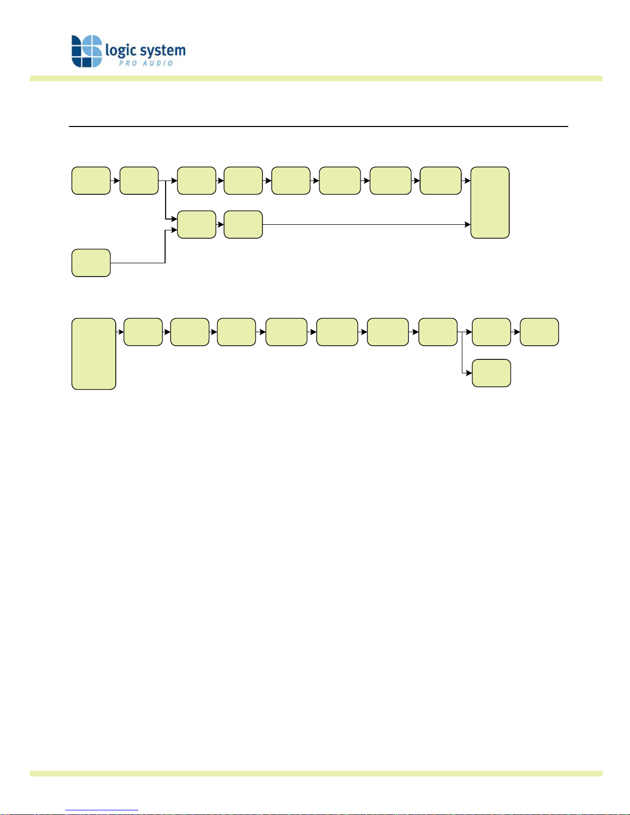
Input DSP block diagram
Input A
Input
LED’s
Input
Gain
Delay
4th Order
HPF
Low
Shelf EQ
Six Band
PEQ
High
Shelf EQ
Routing
Input B
SUM - 6dB
NB. Channel B processing is
identical to Channel A but for
clarity it is not shown
Output DSP block diagram
Routing
Delay
8th Order
HPF
8th Order
LPF
Low
Shelf EQ
Six Band
PEQ
High
Shelf EQ
Output
Gain
Mute Limiter
Metering
Stereo / Mono Formats
There is only one ‘standard’ layout of the processing blocks, but flexible routing and control
linking allows this layout to be adapted to a wide variety of applications.
There are two ‘Formats’, Mono or Stereo. With the Mono format, all outputs have unique
parameter settings, and all outputs are identical in terms of processing functions and routing
capability. This is the most flexible Format.
Stereo format pairs the inputs and outputs for stereo operation, the parameters of each member
of the pair being identical. The routing of inputs to outputs is fixed. This format is intended for
symmetrical stereo operation, eliminating the need to make identical parameter adjustments for
each channel.
The channel pairing is:
• Left and Right Inputs
• Outputs 1 (routed from L input) and 3 (routed from R input) [1 and 4 for DP2160]
• Outputs 2 (routed from L input) and 4 (routed from R input) [2 and 5 for DP2160]
• [Outputs 3 (routed from L input) and 6 (routed from R input) – DP2160 only]
Page 19
Logic Digital Controller
User Guide version 3 Page 19 of 31
DSP processing
Input Channels
Gain
In A Gain
0.0dB
ab
c
a
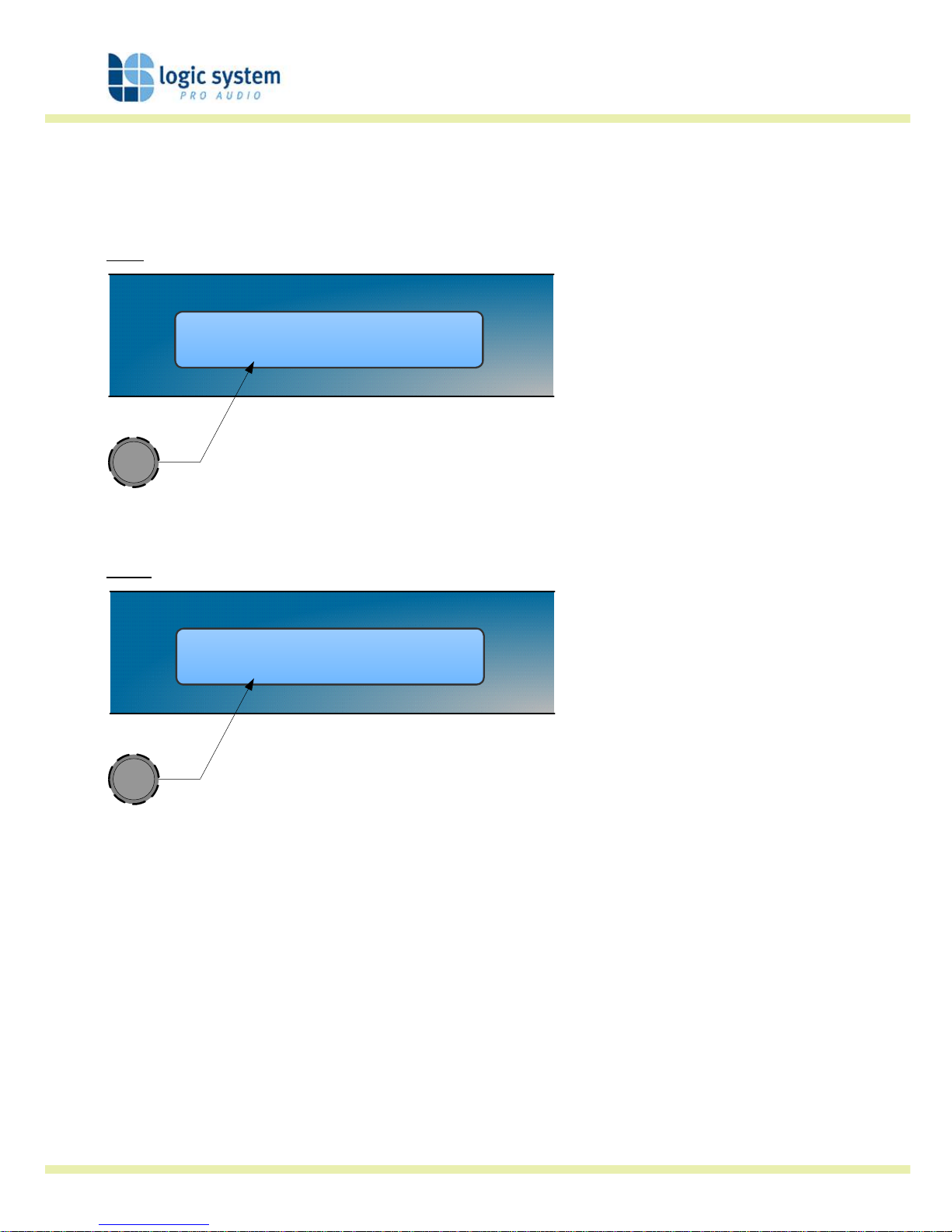
• Knob A: Gain, adjustable in 0.2dB steps from –80 dB to +20dB
Delay
In A Delay
1.50ms
ab
c
a
• Knob A: Delay, adjustable in variable steps from 0 to 400ms
The delay parameter is adjustable in fine steps at low values; the adjustment becomes
progressively coarser as the value increases. The velocity sensitive Parameter Knobs therefore
provide accurate setting of driver offset delays (typically below 10ms) and rapid setting of
longer system alignment delays.
Page 20
Logic Digital Controller
User Guide version 3 Page 20 of 31
High Pass Filter
In A Freq Shape
HPF 20.0Hz LR24
ab
c
a b
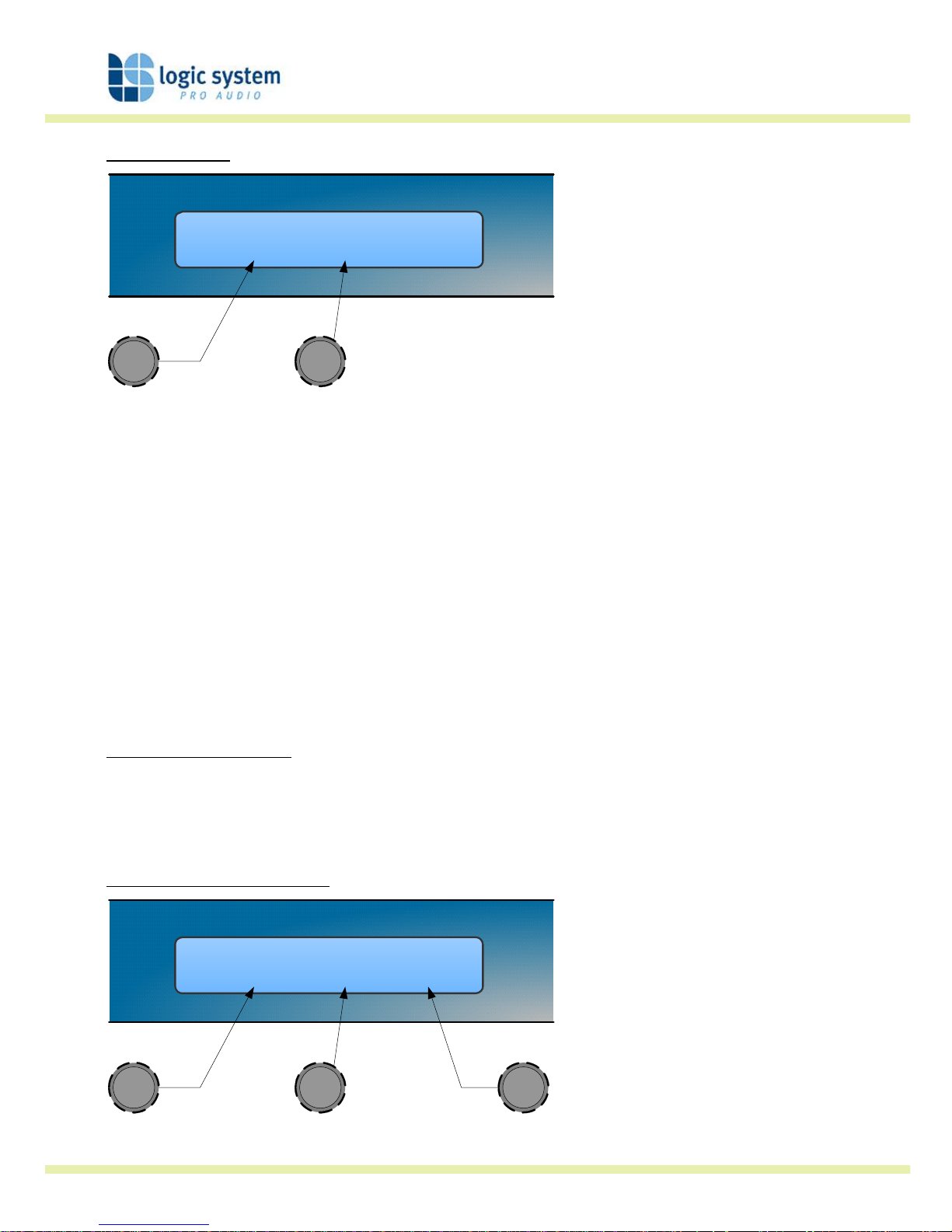
• Knob A: Frequency, out (off), 10.0Hz to 25.6kHz in variable steps
• Knob B: high pass filter type
System high pass filtering is provided for the input signal. This is the preferred location for high
pass filtering as it affects all outputs and can therefore improve inter-band phase relationships.
Filter type is selectable from Butterworth, Bessel, Linkwitz-Riley and Hardman. Filter slopes of
up to 4th order or 24dB / octave are provided. Not all filter types are available in all slopes. For
example 18dB / octave Linkwitz-Riley filters do not exist.
The Hardman type filter is always described by its’ order as the filter becomes progressively
steeper rather than following a linear slope so a dB/octave description is not accurate.
Parametric Equalisation
Eight sections of equalisation are provided, two shelving filters and six fully variable parametric
sections.
High and Low shelving filters
In A Freq Slope Gain
EQ1 100Hz 12dB 0.0dB
a
b
c
a b c
• Knob A: Frequency, 10.0Hz to 25.6kHz in variable steps
Page 21
Logic Digital Controller
User Guide version 3 Page 21 of 31
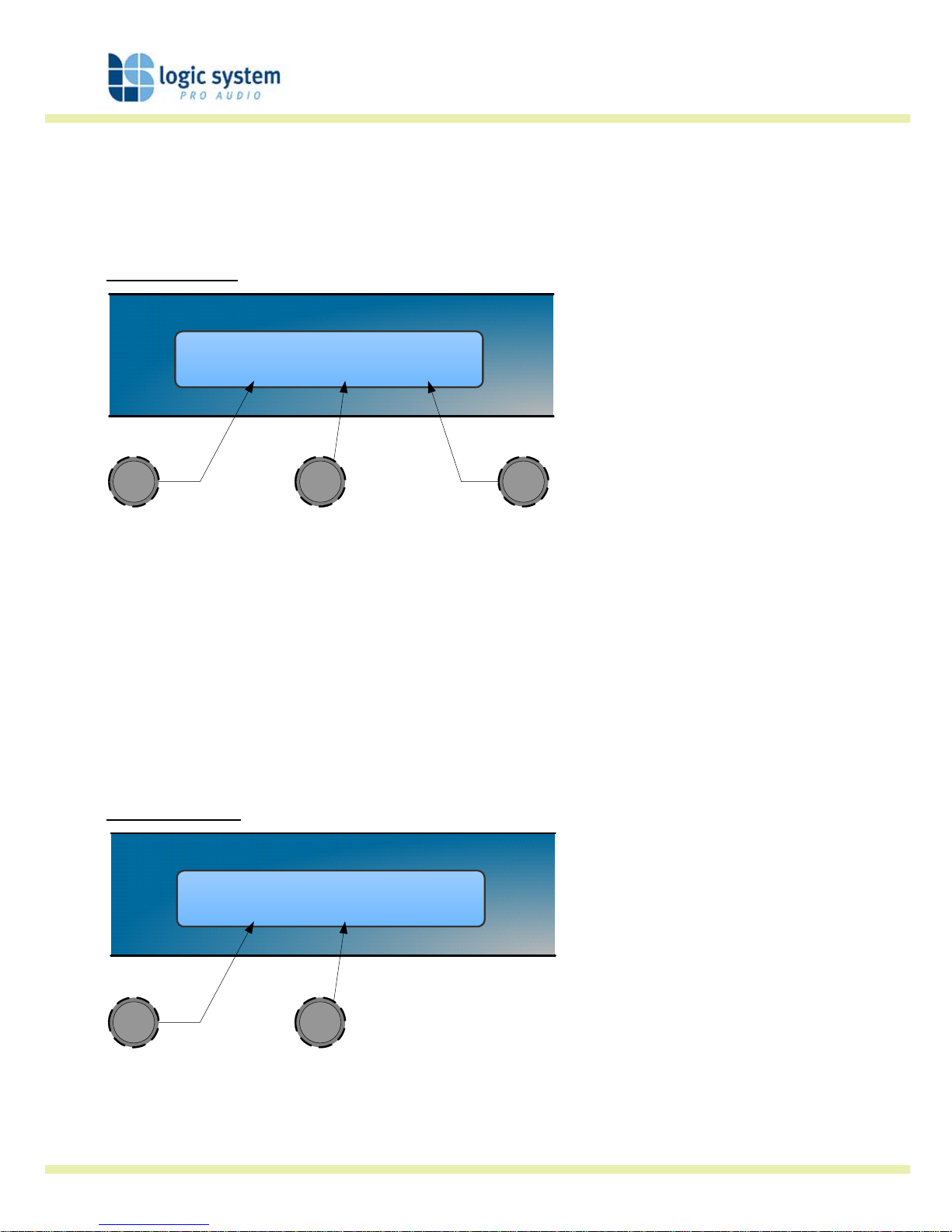
• Knob B: Slope, 6 to 12dB / octave in 1dB steps
• Knob C: Gain, +/-15dB in 0.2dB steps
The frequency is specified as point where the filter deviates by 3dB from the gain value.
Parametric filters
In A Freq Width Gain
EQ1 100Hz 1.4Q 0.0dB
a
b
c
a b c
• Knob A, Centre Frequency, 10.0Hz to 25.6kHz in variable steps
• Knob B, Width, display selectable, Q or BW (Bandwidth)
BW adjustable from 0.05 to 5 octaves in variable steps
Q adjustable from 14.2 to 0.2 in variable steps
• Knob C, Gain, +/-15dB in 0.2dB steps
Output Channels
Gain and Polarity
Out1 Gain Pol
0.0dB Rev
ab
c
a b
• Knob A: Gain, adjustable in 0.2dB steps from –80 dB to +20dB
• Knob B: Polarity, selectable, normal or reversed with reference to other outputs
Page 22
Logic Digital Controller
User Guide version 3 Page 22 of 31
Delay
Out1 Delay
1.50ms
ab
c
a
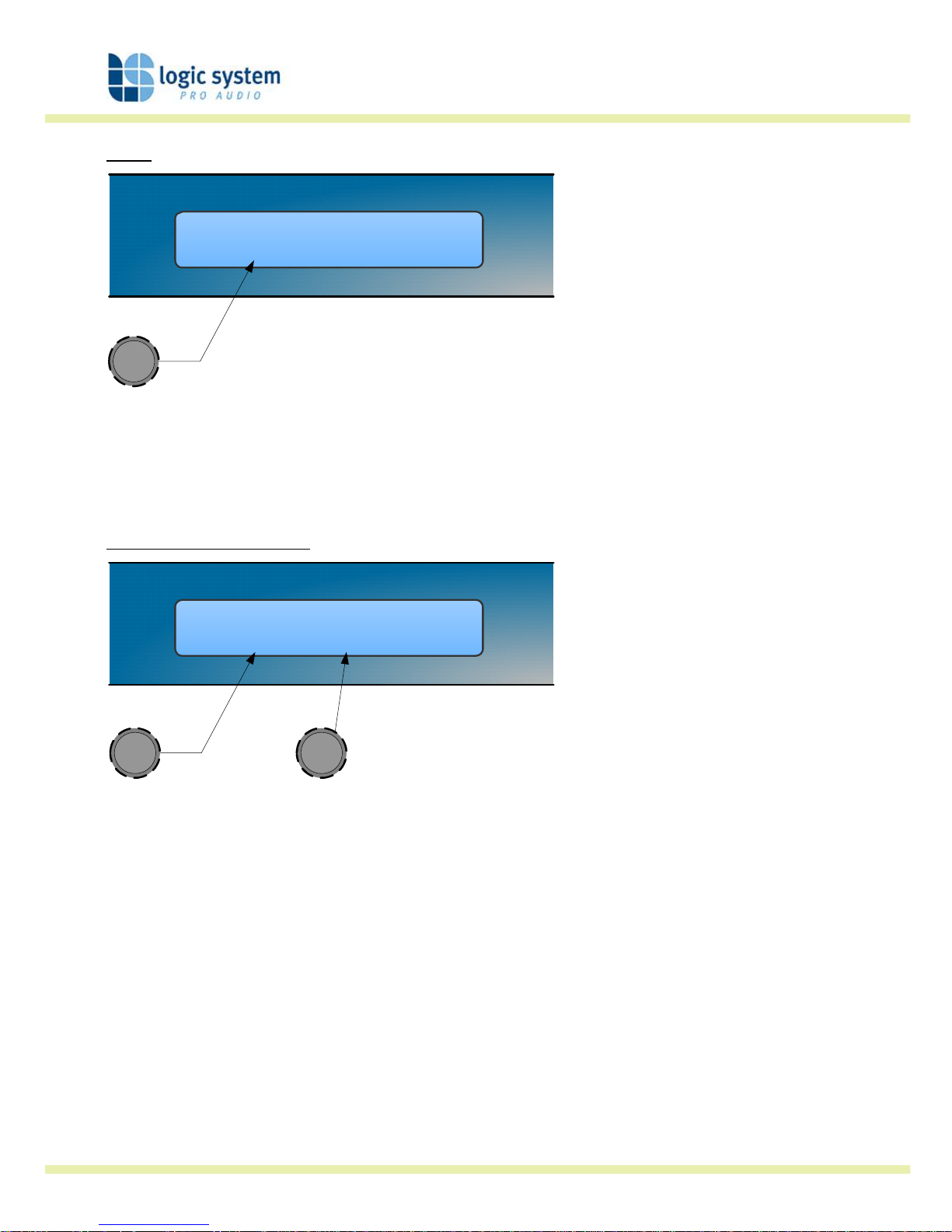
• Knob A: Adjustable in variable steps from 0 to 80ms
As for input delay, velocity sensitive Parameter Knobs provide finer adjustment at low levels and
rapid selection of higher values.
High and Low Pass Filters
Out1 Freq Shape
LPF 2.50k LR24
ab
c
a b
• Knob A: Frequency, <<out, 10.0Hz to 25.6kHz, out>>
• Knob B: high pass filter type
Filter type is selectable from Butterworth, Bessel, Linkwitz-Riley and Hardman. Filter slopes of
up to 8th order or 48dB / octave are provided. Not all filter types are available in all slopes. For
example 18dB / octave Linkwitz-Riley filters do not exist.
The Hardman type filter is always described by its’ order as the filter becomes progressively
steeper rather than following a linear slope so a dB/octave description is not accurate.
Page 23
Logic Digital Controller
User Guide version 3 Page 23 of 31
Parametric Equalisation
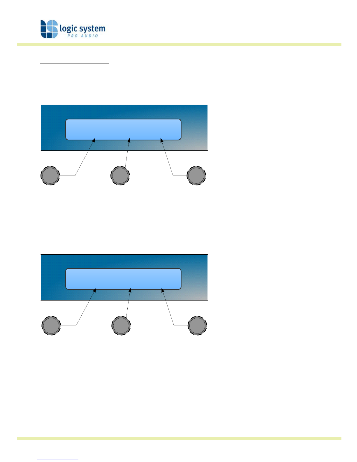
Eight sections of equalisation are provided in a similar format to the input channel equalisation;
two shelving filters and six parametric.
Out1 Freq Slope Gain
EQ>- 100Hz 12dB 0.0dB
ab
c
a cb
• Knob A: Frequency, 10.0Hz to 25.6kHz in variable steps
• Knob B: Slope, 6 to 12dB / octave in 1dB steps
• Knob C: Gain, +/-15dB in 0.2dB steps
The frequency is specified as point where the filter deviates by 3dB from the gain value.
Out1 Freq Width Gain
EQ1 100Hz 1.4Q 0.0dB
ab
c
a b c
• Knob A, Centre Frequency, 10.0Hz to 25.6kHz in variable steps
• Knob B, Width, display selectable, Q or BW (Bandwidth)
BW adjustable from 0.05 to 5 octaves in variable steps
Q adjustable from 14.2 to 0.2 in variable steps
• Knob C, Gain, +/-15dB in 0.2dB steps
Page 24
Logic Digital Controller
User Guide version 3 Page 24 of 31
Limiters
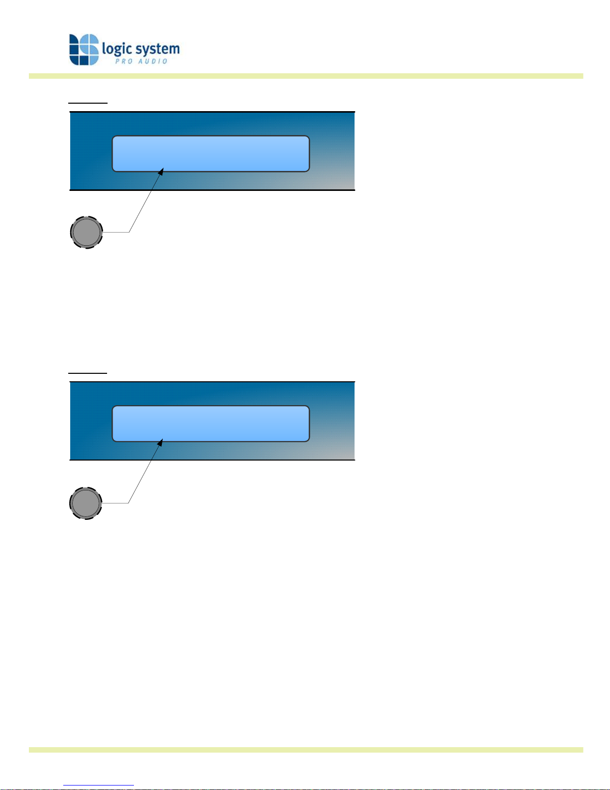
Out1 Thresh
LIM 4.0dB
ab
c
a
• Knob A: Threshold, -40dBu to 20dBu in 0.2dB steps
A high performance, low distortion limiter is provided on each output. Threshold is user
adjustable; all other parameters are carefully calculated dependant on configuration to provide
clean and effective control of signal dynamics.
Routing
Out1 Source
Inp A
ab
c
a
• Knob A: Output source, selectable; Input A, Input B or Sum A+B
Configures the routing from input to output. This function is only available in mono format
Presets.
Page 25
Logic Digital Controller
User Guide version 3 Page 25 of 31
Utilities
Utility functions
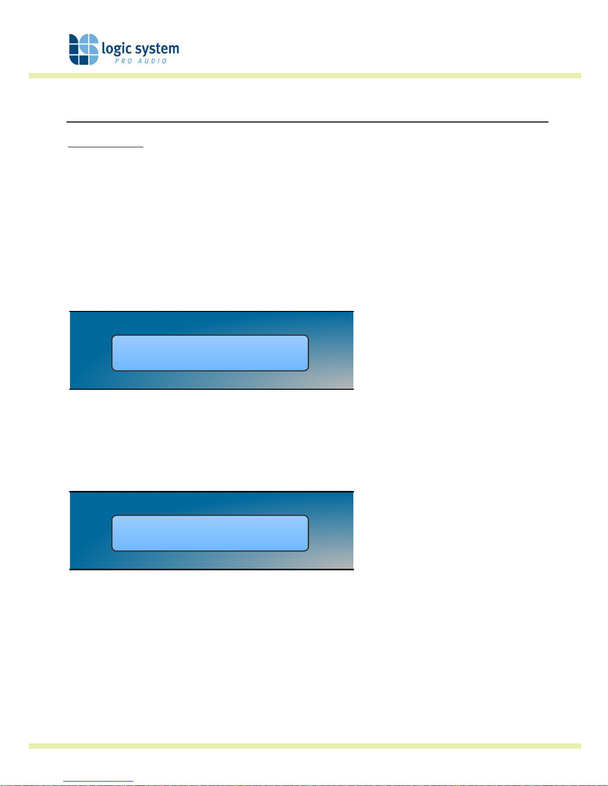
Three utility functions are provided to adjust screen contrast, the display units used for
parametric equalisation bandwidth and switch between stereo and mono mode.
The device automatically adjusts for the variations in display contrast as the temperature of the
LCD changes. The screen contrast utility control sets the base contrast of the screen and also
allows optimization for a given viewing angle.
Parametric equalisation width parameters can be displayed in either ‘Q’ or bandwidth, expressed
in octaves.
Util Screen ParaEQ
1.. 100% BW=Q
ab
c
Care should be taken when swapping between mono and stereo mode as the parameter set for
the left hand channels will be copied to the right hand side, overwriting those settings. This is
not reversible and could represent quite a significant and potentially damaging change to the
processing.
Util Mode
..2 Mono
ab
c
Page 26
Logic Digital Controller
User Guide version 3 Page 26 of 31
Factory Presets
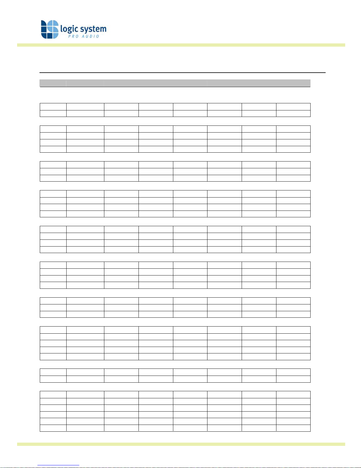
location preset name out1 out2 out3 out4 out5 out6
Basic default programs
1 basic stereo < 100 100 ~ 1K 1K > < 100 100 ~ 1K 1K >
2 basic mono full range full range full range full range full range full range
Page 27
Logic Digital Controller
User Guide version 3 Page 27 of 31
EQ and Filter Response Graphs
100 1.10
3
1.10
4
36
30
24
18
12
6
0
6
6dB/Oct
12dB/Oct
18dB/Oct
24dB/Oct
48dB/Oct
Butterworth
Frequency, Hz
Magnitude, dB
100 1.10
3
1.10
4
36
30
24
18
12
6
0
6
12dB/Oct
24dB/Oct
48dB/Oct
Linkwitz-Riley
Frequency, Hz
Magnitude, dB
Page 28
Logic Digital Controller
User Guide version 3 Page 28 of 31
100 1.10
3
1.10
4
36
30
24
18
12
6
0
6
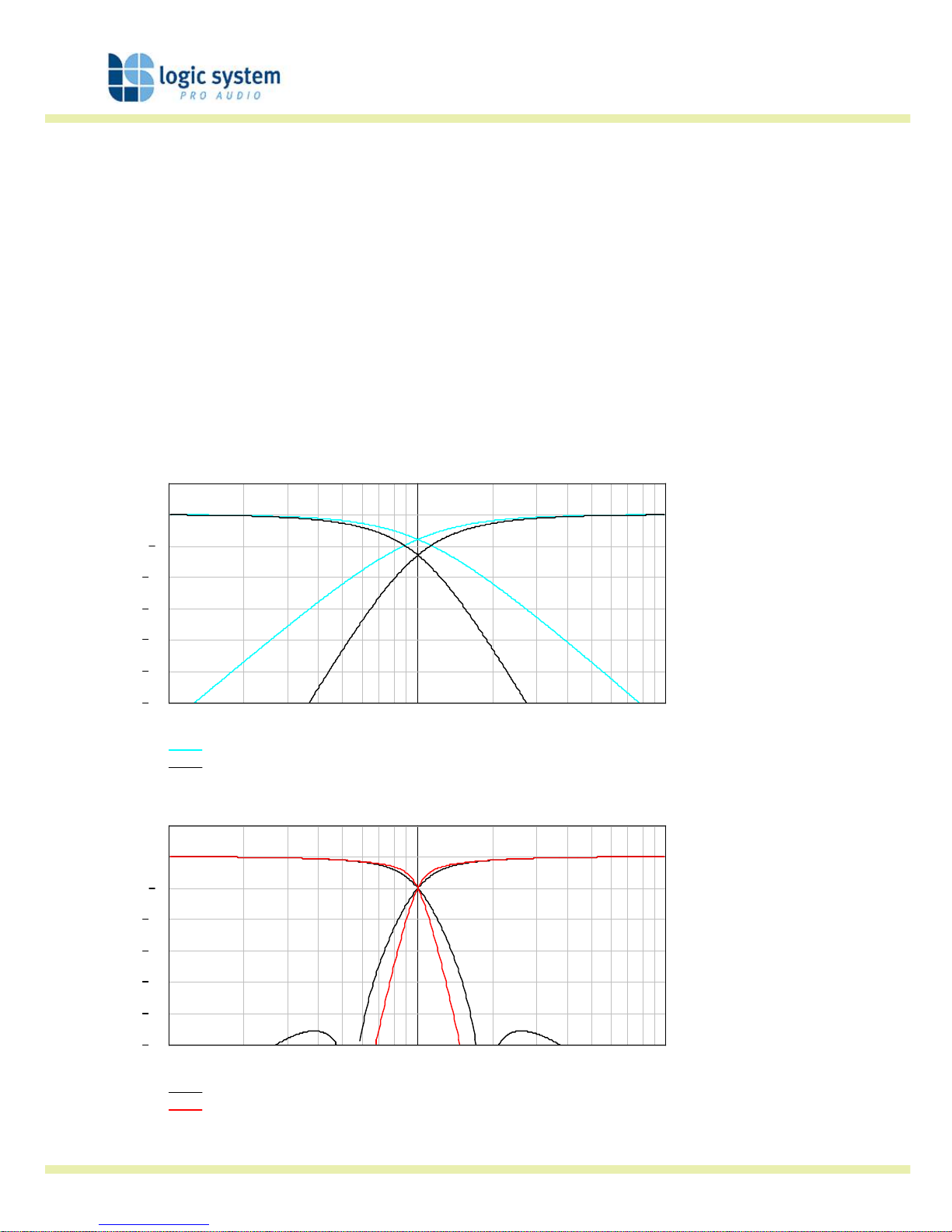
12dB/Oct
24dB/Oct
Bessel
Frequency, Hz
Magnitude, dB
100 1.10
3
1.10
4
36
30
24
18
12
6
0
6
4th Order
8th Order
Hardman
Frequency, Hz
Magnitude, dB
Page 29
Logic Digital Controller
User Guide version 3 Page 29 of 31
100 1.10
3
1.10
4
15
10
5
0
5
10
15
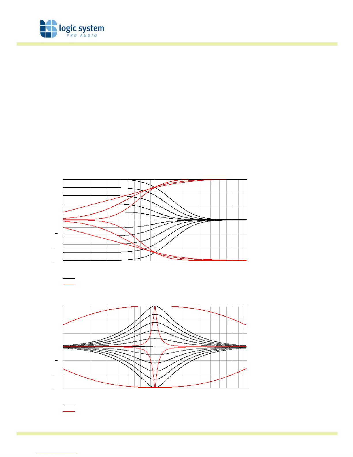
Low shelf, varying Gain
High shelf, varying Slope
Shelving EQ
Frequency, Hz
Magnitude, dB
100 1.10
3
1.10
4
15
10
5
0
5
10
15
Varying Gain
Varying Bandwidth
Parametric EQ
Frequency, Hz
Magnitude, dB
Page 30

Logic Digital Controller
User Guide version 3 Page 30 of 31
Technical Specification
General
Inputs……………………………………………….. 2
Input Impedance………………………………… > 10k Ohm Electronically balanced
Maximum Input level…………………….…… +20dBu
Outputs…………………………………………….. four [LOGIC 24] or six [LOGIC 26]
Output Impedance……………………………… <100 Ohm, ground balanced
Maximum Output Level……………………… +202dBu into 600ohm load
Sample Rate………………………..…………….. 96kHz
Bit Depth…………………………………………… 24 bit
Frequency Response………………………………………... 10Hz to 40kHz, +/- 3dB (filters disabled)
20Hz to 20kHz, +/- 0.5dB (filters disabled)
THD………………………………………………….. <0.01%, (+10dBu, 20Hz to 20kHz, 30kHz bandwidth)
Dynamic Range…………………………………. >112dB (A weighted, 22kHz bandwidth)
>109dB (un-weighted, 22kHz bandwidth)
Serial Comms Data…………………………….. 38.4kbaud, format: 8 data, 1 stop, no parity
Processing
Gain………………………………………………….. +20dB to -80dB and mute, 0.2dB steps
Output Ch. Source……………………………… Input A, Input B and SUM
HP filter frequency……………………………… Off, 10Hz to 25.4kHz, 1/36 octave steps
LP filter frequency………………………………. 10Hz to 25.4kHz and off, 1/36 octave steps
LP / HP filter type……………………………….. 12, 18 & 24dB/octave Bessel and Butterworth
12, 24 and 48dB/octave Linkwitz Riley
4
th
or 8th order Hardman
Delay…………………………………………………. Input 400ms, output 80ms
Limiter………………………………………………. High performance limiter, adjustable threshold in 0.2dB steps, automatic time constants
EQ frequency……………………………………… 10Hz to 25kHz, 1/36 octave steps
EQ gain……………………………………………… +15dB to -15dB, 0.2dB steps
EQ width…………………………………………… 5.0 to 0.1 octaves bandwidth, 1/36 octave steps
Connectors
Audio inputs……………………………………… 3 pin female XLR
Audio outputs……………………………………. 3 pin male XLR
Serial comms…………………………………….. Future option
Network comms………………………………… Future option
Mains……………………………………………….. 3 pin IEC
Mains Power……………………………………… Universal switch-mode PSU, 85v to 250v AC, 50 / 60Hz
Consumption…………………………………….. < 25watts
Dimensions……………………………………….. 44mm (H), 482mm (W), 254mm (D)
Weight…………………………………………………. 2.7 Kgs net
Page 31

Logic Digital Controller
User Guide version 3 Page 31 of 31
Logic System Pro Audio Ltd. Units 5 & 6 Sandars Road, Heapham Road industrial Estate,
Gainsborough, Lincolnshire, DN21 1XT.
T: +44(0)1427 611791 F: +44(0)1427 677008
E: [email protected] W: www.logic-system.co.uk
 Loading...