

Page 1
OPERATING INSTRUCTION
140104, Russia Ramenskoe city, Moscow region, 100th Svirskoi Divizii st., 11
tel/fax (495) 221-75-58, 221-75-59, 221-75-49
www.logsys.ru
E-mail: [email protected]
Search kit «ОКО-2»
Operating Manual
2008г
«Logical systems»
Page 2

3
1. CONTENTS
1. CONTENTS ......................................................................................................................3
2. DESCRIPTION OF DEVICE OPERATION....................................................................4
2.1 Device designation......................................................................................................4
2.2 Device structure ..........................................................................................................4
2.3 Arrangements of device operation..............................................................................5
2.4 Marking and sealing....................................................................................................5
2.5 Description and operation of the device component elements ...................................5
3. WORK WITH THE DEVICE ...........................................................................................8
3.1 Assembly of the device...............................................................................................8
3.2 The device in operating position...............................................................................10
3.3 Preparation for scanning ...........................................................................................11
3.4 Set parameters of scanning .......................................................................................12
3.5 The operation of scanning.........................................................................................14
3.6 Detection of movement.............................................................................................16
3.7 General recommendations ........................................................................................19
3.8 Functioning of “Start-Stop” button...........................................................................19
3.9 Device Switching off and Disassembling.................................................................19
3.10 Viewing files...........................................................................................................20
3.11 Settings....................................................................................................................23
4. File Transfer from BUOI into a computer.......................................................................25
5. Work with SK «Око-2» along with using a notebook. ...................................................28
6. Requirements on safe operation and electromagnetic compatibility...............................29
7. Technical maintenance. ...................................................................................................29
7.1 General instructions. .................................................................................................29
7.2 Maintenance procedure.............................................................................................29
8. Routine Servicing. ...........................................................................................................30
9. Storing .............................................................................................................................30
10. Transportation................................................................................................................31
11. Utilization ......................................................................................................................31
Page 3
4
2. DESCRIPTION OF DEVICE OPERATION
2.1 Device designation
Search kit «OKO-2» is automated device and is designed for operative searching and detection
dotted and extended metal and nonmetallic objects in various nonmetallic environments (ground,
water, building designs and etc.)
.
2.2 Device structure
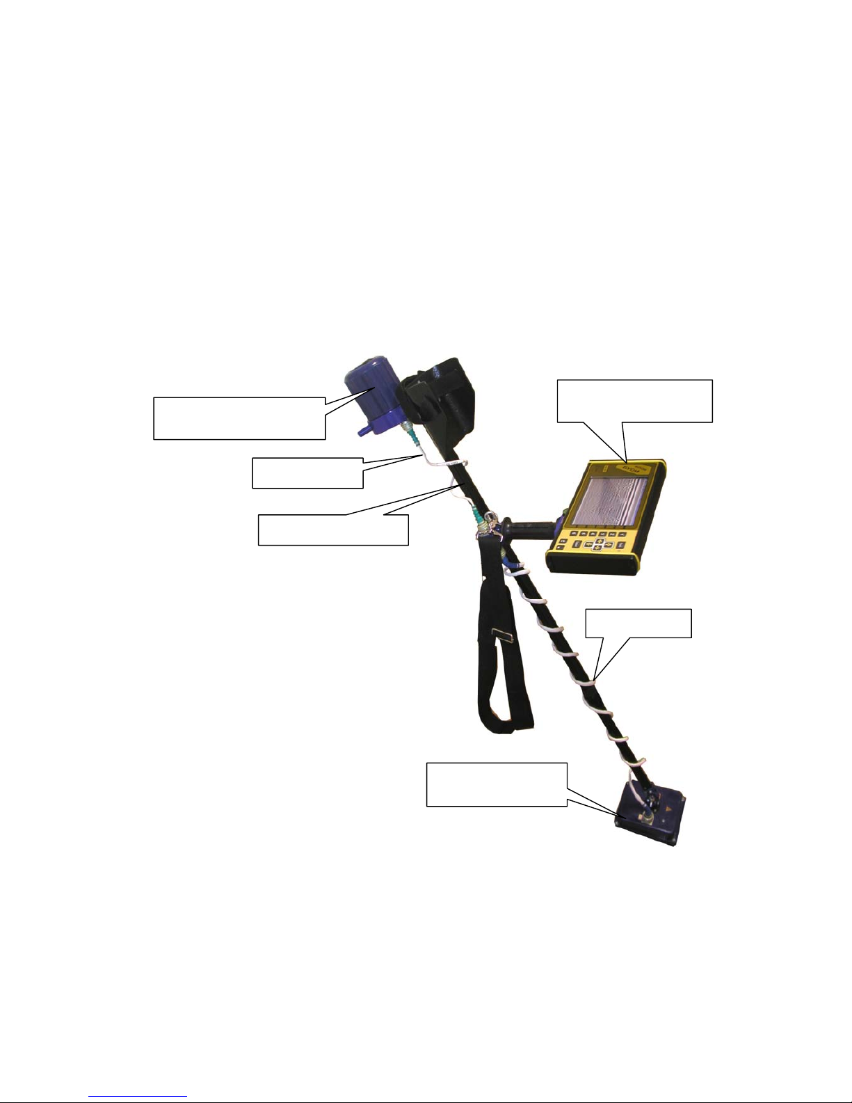
The device is the monoblock. The monoblock consists of two changeable receiving and
transmitting antenna units (BAPP), control, processing and indication unit (BUOI), folding handle rod
(SSHR), off-line power supply unit (BP) and sets of cables (figure 2.2.1).
Figure 2.2.1. Complex with BAPP-II
Off-line power supply unit
(BP 3,8/12)
Cable BP (БП)
Folding handle rod
Cable BAPP
Changeable antenna
unit
Control processing
indications unit
Page 4

5
2.3 Arrangements of device operation
The SK operation is based on well-known radiolocation principals. The SK operation is based
on ability of radio waves to be reflected from sections of environment boundaries with a different
permittivity.
Short signal pulses are applied for subsurface radiolocation.
In order to form such pulses the excitation of the wideband transmitting antenna caused by the
voltage swing is used. The direct processing of pulses of such small duration (hundreds picoseconds) is
rather complex. So the stroboscope transformation method is used.
The control, processing and indication unit (BUOI) is to form and to transfer the instructions to
the receiving unit of transmitting antenna unit (BAPP). Receiving unit is to form all the necessary
signals of control for switching on the transmitter. The transmitting unit is to form the signals to the
tested environment (cargo). The reflected signals are received by the receiving antenna unit BAPP,
processed, and transferred to the BUOI.
The control, processing and indication unit is to form two-dimensional image of received
signals and then are to display them on the indicator (screen) in the real time.
The special cable connection on BUOI, cable connect BUOI and computer by interface
Ethernet is stipulated in the device for connecting with the external computer, and for forming three
dimensional image.
2.4 Marking and sealing
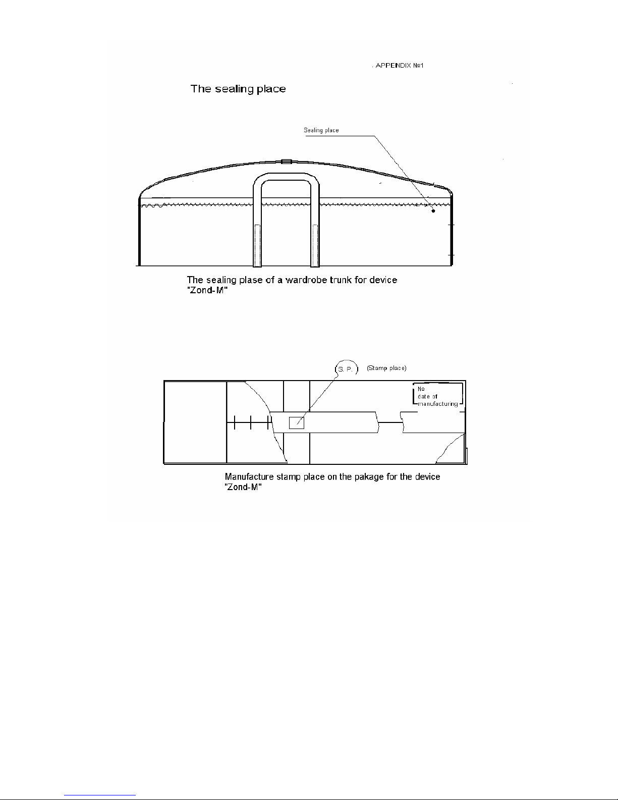
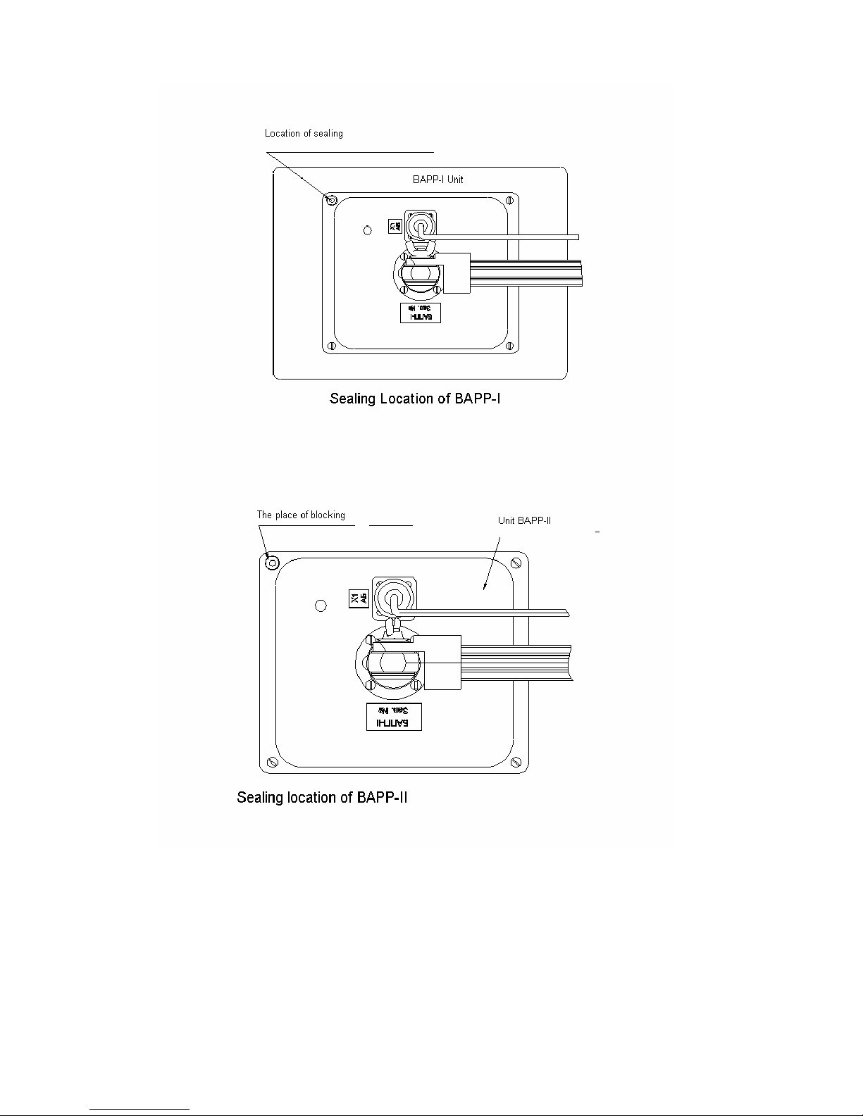
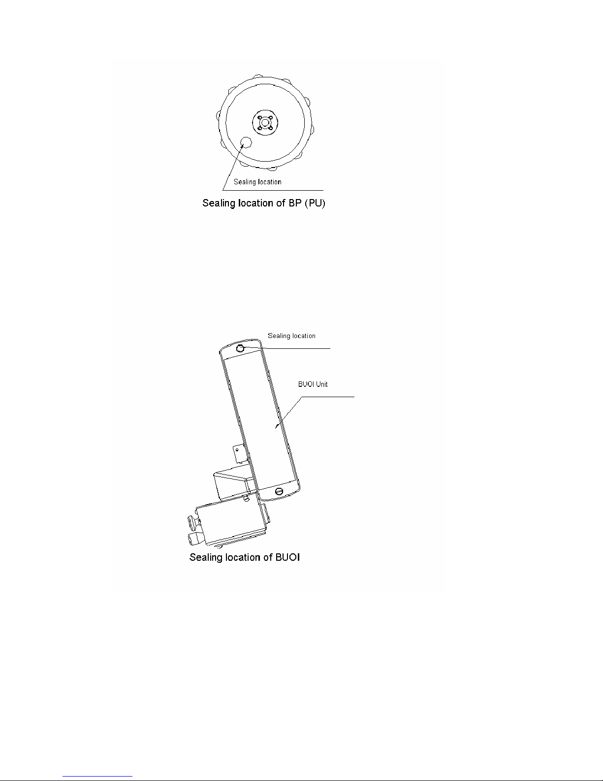
The location of sealing wardrobe trunk, packing, BAPP I, BAPP II, BUOI and BP, are
represented in the Appendix 1.
The seal of a wardrobe trunk is located on a long side part of wardrobe trunk, in the upper right
corner.
2.5 Description and operation of the device component
2.5.1 The general
The main components of the device SK is the control, processing and indication unit (BUOI),
receiving and transmitting antenna unit (BAPP) I and II range, and off-line power supply unit (BP).
Receiving and transmitting antenna unit (BAPP) is designed as a separate part, which is
attached to one end of the folding handle rod. The off-line power supply unit (BP) is to attached to the
second end of the folding handle rod. The control, processing and indication unit (BUOI) is attached in
the middle part of the folding handle rod. Connection between the units is made using connecting
cables.
Two changeable BAPP units: I and II range are used for operation in different frequency
ranges. The length of folding handle rod in a fields status is 0,88 m, in operating position the length is
(regarding on the height of a person) – up to 1,53 m.
The off-line power supply unit (BP 3,8/12) provides the non-stop work of the device for not
less than 4 hours.
Page 5

6
2.5.2 Operation device of component parts
Receiving and transmitting antenna unit (BAPP)
Receiving and transmitting antenna unit functionally consists of receiving, transmitting units
and receiving and transmitting antenna unit with volumetric damping resonator.
Receiving unit
The receiving unit functionally consists of receiving antenna unit, the scan stroboscopic device,
selection and storage device (SD) and the control unit.
Reflecting from the inhomogeneity in the tested environment the signals are coming from input
receiving antenna unit to output SD, where they are stored at the time of processing. The signals are
coming from SD to the analog digital converter (ADC). The microprocessor receives the transferred
digital signal. The control unit is to realize the preliminary processing of the received data and to
transfer the data to the BUOI.
The signals for start of the transmitter are to form in the control unit and are to transfer to the
transmitting unit.
The scan stroboscopic device is to form the pulses for the SD operation. The selection and
storage unit is to remember the signal by control pulse and is to store it more than 1 micro second. It is
enough time for ADC to transfer the processed analog signal to a digital code. BAPP II is to operate in
the range, where the frequency ranges ADC are to allow the transformation of analog signals into the
digital code without using SD. So for the range of BAPP I the signals from input of receiving antenna
unit are coming to output of ADC.
The sensitivity of the receiving device is not worse than 300 microvolt.
Transmitting unit
The transmitting unit functionally consists of transmitting antenna unit, pulse shaper and high
voltage-power supply unit. The pulse shape at receipt of the starting pulse are to form the (короткий
перепад high voltage) which is to activate the transmitting antenna. The high voltage power supply
unit is designed to transform the voltage of 12V into power which is necessary for operation the pulse
shaper. (duration of a pulse of 1,5-2,2 nanoseconds with fronts up to 0,2-0,3 nanoseconds and
frequency of following 200 KHz.)
The control, processing and indication unit (BUOI)
The control, processing and indication unit is based on the digital signal processor and
functionally consists of all climatic liquid crystal indicator, the control device and the keyboard. All
operations are realized using the buttons located on the front panel. Using the buttons the operator is to
choose the required points or parameters in menu which are displayed on the indicator and is to change
them according with the required task.
According with the choice of the mode and parameters, the control device is designed on the
signal processor, forms instructions and transfers them to the antenna unit (BAPP) using interface RS-
485.
The accepted data are processed and displayed on the screen.
BUOI has the high definition (640x480 points) liquid crystal color display.
BUOI allows to keep the received data in the memory 1Gb (this size of memory is sufficient
for storage approximately 240000 paths), that at the step of scanning 5 cm is about 12000 m of a
continuous profile
Page 6

7
The data from BUOI can be copied on a personal computer on interface Ethernet. The
transferring order is described in the User’s manual.
The further data processing can be made on a personal computer using Geascan32 software
(see. The User s guide program Geoscan32).
Autonomous power supply unit (BP)
The autonomous power supply unit (BP) consists of ten Ni-Mh accumulators and the
accumulator indicator of the category, which is control and indicate of the accumulator battery. BP
3,8/12 is equipped with self-recovering fuse. The voltage is supply from BP to the BUOI and BAPP
using power supply cable.
Page 7
8
3. WORK WITH THE DEVICE
3.1 Assembly of the device
1. Take from wardrobe trunk SSHP, BP, BUOI, BAPP I/II, cable BP and cable BAPP;
2. Choose the required BAPP according with the depth of search. At depth up to 1 m - BAPP II, from
1 up to 3 m – BAPP I;
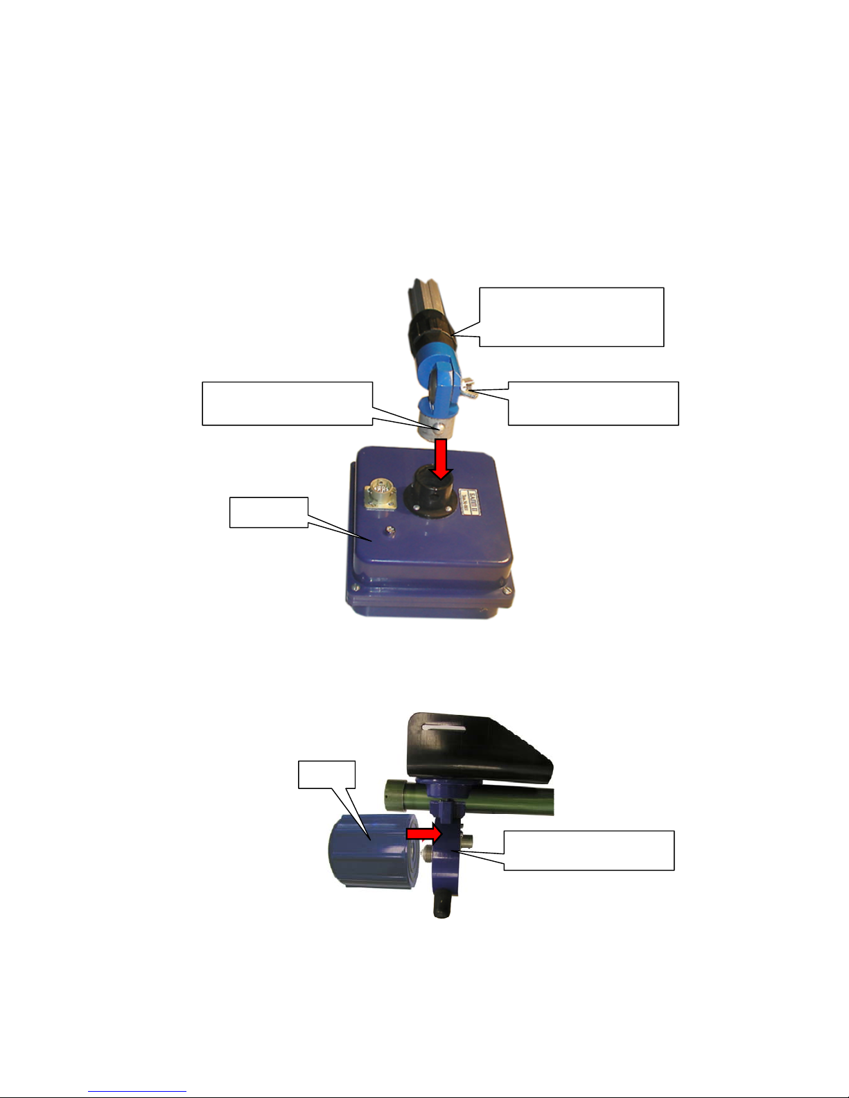
3. Fix BAPP on the foldable handle rod in such away that spring-force fixing ledge of foldable
handle rod is to be correspond to the socket of the supporting element on the BAPP case (figure
3.1.1);
Figure 3.1.1. BAPP Supporting to the folding handle rod.
4. Rotating clock-wise twist completely charged off-line power supply (BP) unit on the folding
handle rod (figure 3.1.2);
Figure 3.1.2. BAPP Supporting to the folding handle rod.
BP
Supporting node of BP on
the foldin
g
beam-hand
Spring - force fixing ledge
of folding
handle rod
Fixing clutch of position of
retractable element
of folding beam-handle
Bolt fixing the corner of
deflection on BAPP
BAPP I/II
Page 8
9
5. Connect connectors X2 and X3 of folding handle rod with cable of off-line power supply unit
(cable marking «Cab. BP»);
6. Connect connectors X1 BAPP and X1 of folding handle rod by antenna cable unit (cable marking
«Cab. BAPP»);
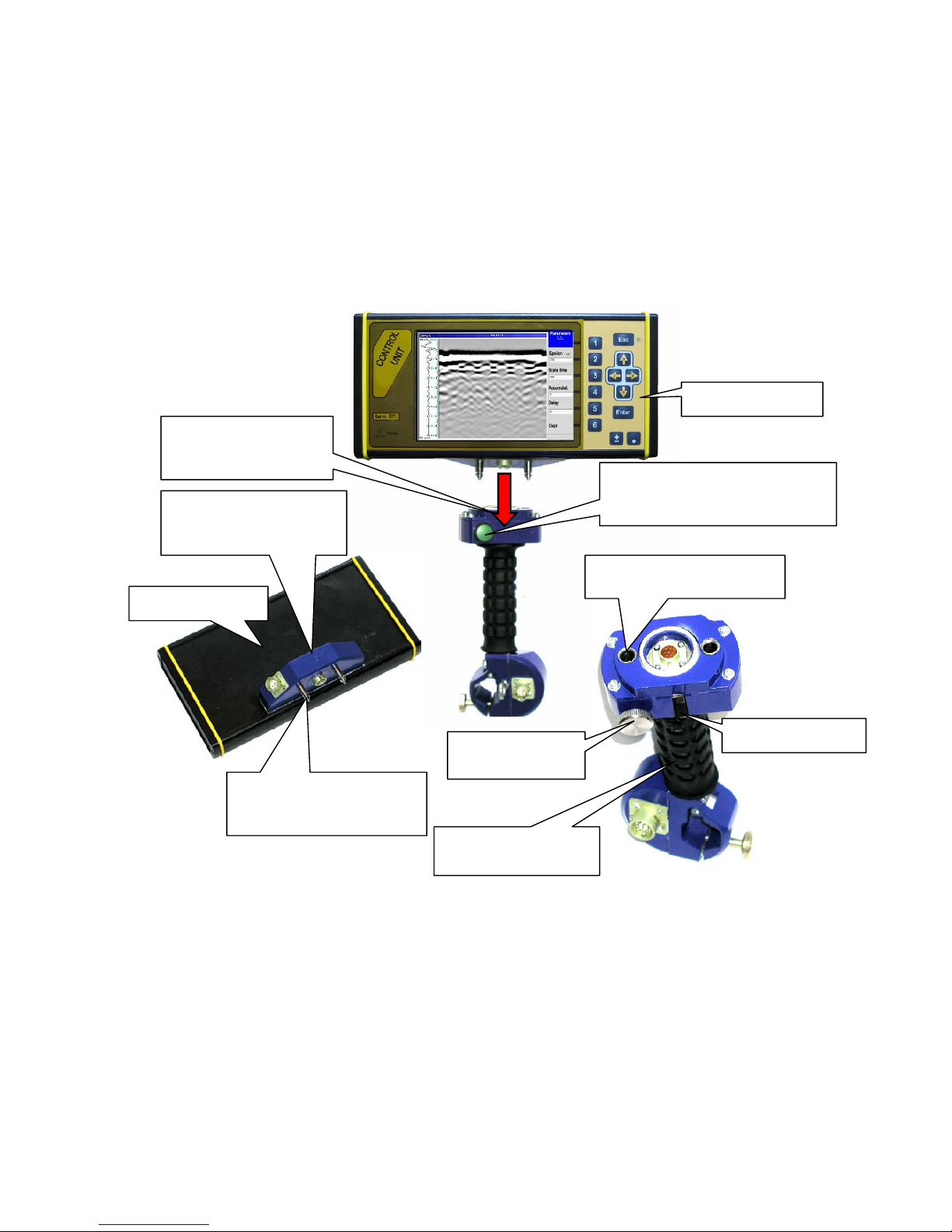
7. Fix the BUOI on the folding handle rod. For that turn clock-wise the fixing arm of BOUI and fix
it in this position, insert guiding connector, to the corresponding parts of the guide supporting element
SSHR and then return a fixing arm of BOUI in a starting position (figure 3.1.3);
Figure 3.1.3. Support BUOI on folding handle rod.
8. Rotating clock-wise (if looking clockwise from the side of the supporting element of BUOI)
release the socket joint fixing the location of a folding handle rod (figure 3.1.3) and pulling the
telescopic of a folding handle rod up to the required value, adjust the length of a f.b.h. (regarding the
standing height of a person), then rotating counterclockwise (if looking from the side of a supporting
element of BOUI) tighten the fixing socket joint;
9. Releasing the screw which fixes the turn of BUOI movement, adjust the turn angle of BUOI in a
relation to a handle rod (figure 3.1.3);
10. On releasing the srew fixing the turn angle of BAPP, adjust the angle of slope of antenna unit in
relation to a handle rod (figure 3.1.1).
BUOI, front view
The «start-stop»button for the
start operating control process
and for finish cargo scanning
Supporting element for
BUOI on folding
handle ro
d
,
font view
Connector guiding for
connection to the folding
handle rod
BUOI, back view
Connector for connection
BUOI to the folding
handle ro
d
Bolt fixing corner
of turning BUOI
Fixing socket joint
BUOI, back view
.
Set of a guide supporting
element
Fixing arm BUOI
Page 9
10
3.2 The device in operating position.
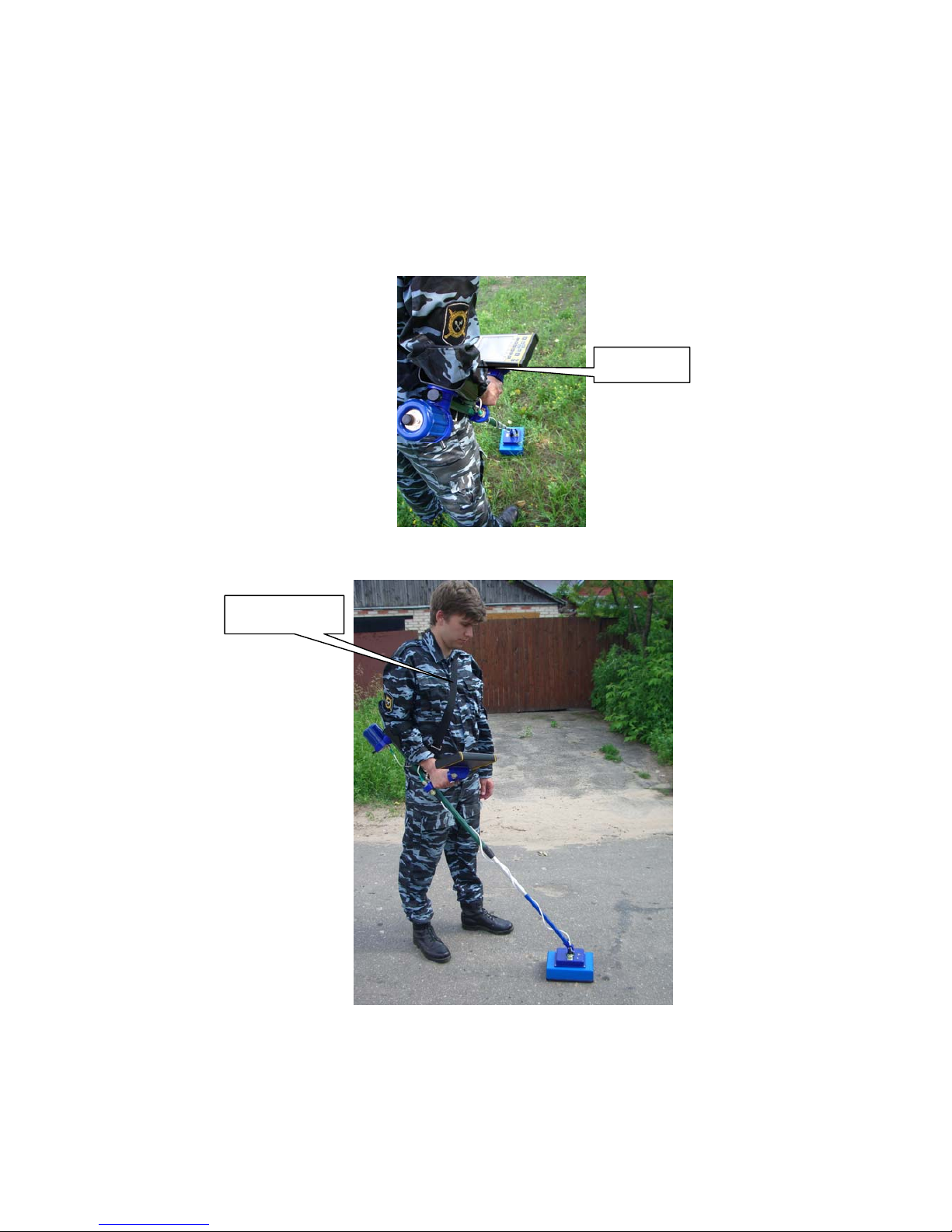
The device is to be in the hand in the position that are shown on the figure 3.2.1 It is necessary
to chose the length of the shoulder belt that the major part of weight SK «Оkо-2» will be on the belt
and at the same time the freedom of moving SK is provided (figure 3.2.2)
BAPP is to be directed at the side of the scanning environment (rejection +_ 20 C from
geometrical axis BAPP) and is to be moved in a parallel surface of cargo, close by or with a slight
detachment (up to 0.1 m) from cargo.
.
Figure 3.2.1. The position of the device in the hands
Figure 3.2.2. Device in operating position
Shoulder belt
Fixing belt
Page 10
11
3.3 Preparation for scanning
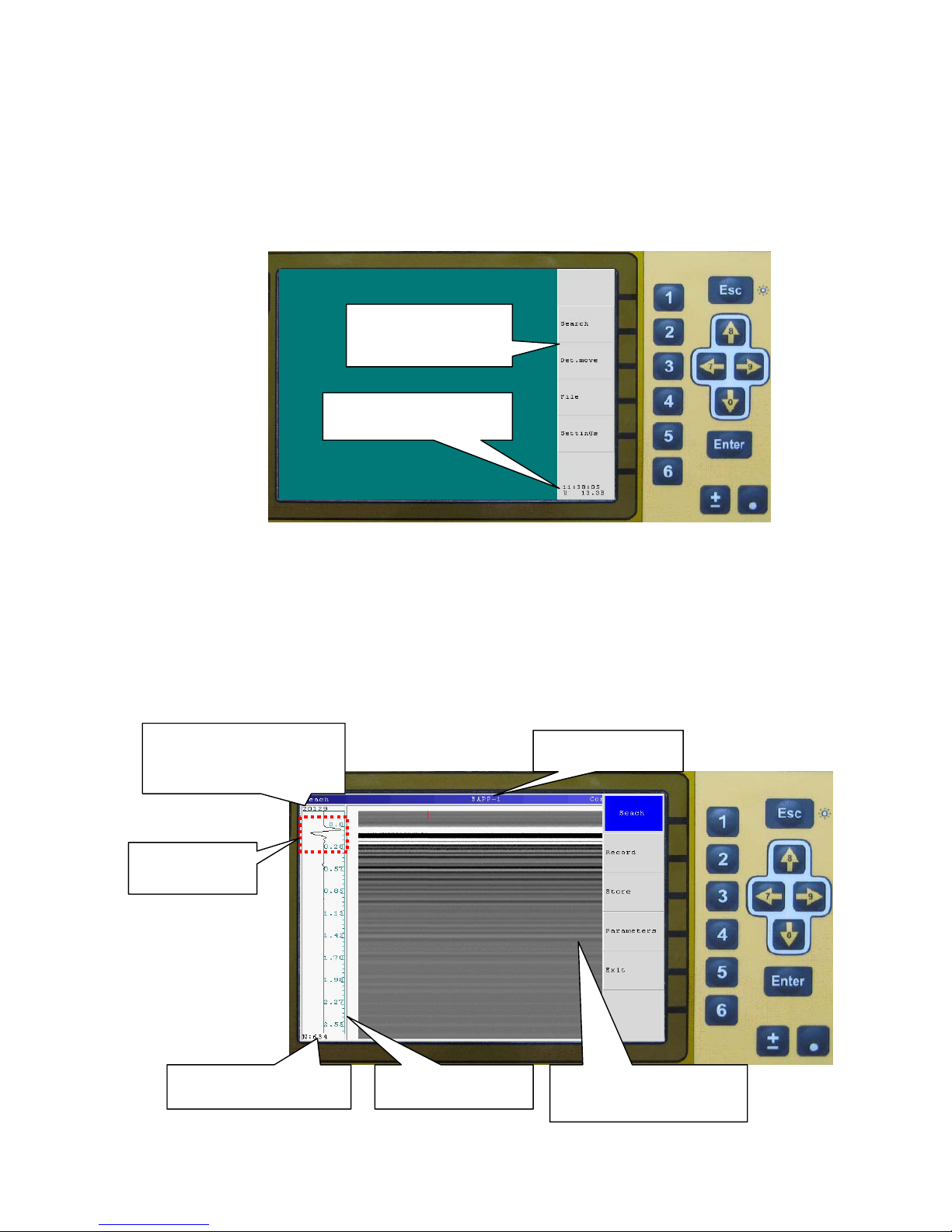
1. Press the key on BP case for switching on the power supply of the device. At that time the Led
indicator is to flash at the BP case and after several seconds of automatically SK testing and shorttime message «Ready», on the BUOI screen is to display operation mode select menu of device
(figure 3.3.1) current voltage of power supply unit and time. The points of menu are to choose by
pressing of functional buttons on the opposite corresponding name functions in the dark
rectangulars in the right part of screen BUOI.
Figure 3.3.1. A device operation mode selection menu
2. Press functional key «2» («Search»). The type of connected BAPP is defined automatically.
After the «Search» mode, the signals are to be displayed on the BUOI. These signals are
reflected from the objects and layers of the scanning zone in the way of black and white lines of
various brightness (colored lines) (figure 3.3.2). The wave picture of current written set of the
reflected signals of the selected record time range (as so-called lines of signal) is at the left side of the
screen. At that time Led indicator on the BAPP case is to be continuously lightning that is to identify
the operation of the transmitting unit of the device.
Figure 3.3.2. Display of written down signals
Signal amplitude of direct
transmitting for current
written set of the reflected
signals
Signal of the direct
transmitting
Number of current written
set of the reflected signals
Depth of scanning in
meters
Wave picture of current
written set of the reflected
signals
Connected type of the
antenna unit
Current functions of
corresponding
functional buttons
Current voltage of power
supply unit and time
Page 11
12
The first three half-periods of each line (on the figure 3.3.2 is allocate by a dotted frame in the
image of wave form) as so called the signal of direct transmitting. The signal of direct transmitting is
not to go to the scanning zone, it is to go directly – from transmitting antenna unit to the receiving and
as a rule, it has the biggest amplitude in the current line. The top area of noise is above the signal of
direct transmitting. The normal position of the signal of direct transmitting – figure 3.3.2.
If after switching on the device, the picture signal of the direct transmitting is below normal
position, using the following buttons “↑” и “↓” it is necessary to modify its position.
By the buttons «←» и «→» it is possible to change the contrast of radarogram (For additional
information use the program GeoScan32 Users manual).
3.4 Set parameters of scanning
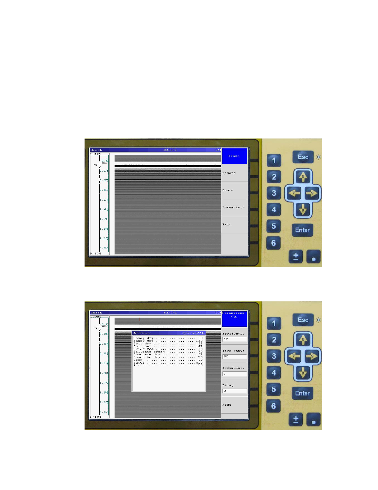
1. Press the key “Esc” to select the measurements mode menu (figure 3.4.1)
Figure 3.4.1. Measurements mode menu
2. Press the functional key «4» («Parameters») to select the options menu of parameter measurements
settings. (figure 3.4.2).
Figure 3.4.2. Menu of parameter measurements settings.
Page 12
13
3. Press the functional key «2» («Epsilon*10», figure 3.4.2) to activate the options of environment
dielectric permeability and with the following buttons “↑”and “↓” and to fix the required value of
dielectric permeability. The value of dielectric permeability multiplied x10 is displayed on the screen
for display convenience of a fractional part of dielectric permeability. This value is used for calculation
of a depth scale during the signals processing. Table on the screen helps to choose value of dielectric
permeability for some environments (figure 3.4.2).
4. Press the functional key «3» («Time range», figure 3.4.2) to activate the options of the depth
scanning (time range of the signals record) of the environment and with the buttons “↑” и “↓” install
the required value.
5. Press functional key «4» («Accumulat.», figure 3.4.2) to activate the mode of the accumulate
signals from antenna. Use “↑” и “↓” buttons for changing this value. Big value of this parameter
increases depth of sensing, but reduces to decrease in speed of scanning.
Recommend values of Accumulate:
1-4 – fast mode of scanning;
8-32 – basic mode of scanning.
6. Press the functional key «5» («Delay», figure 3.4.2) to activate the options of a discrete regulation
signal shift of a direct transmitting to the top profile (smooth regulation of a shift is made with the help
of the following buttons “↑” и “↓” in a «Search» mode) and by the pointers “↑” и “↓” fix the required
value.
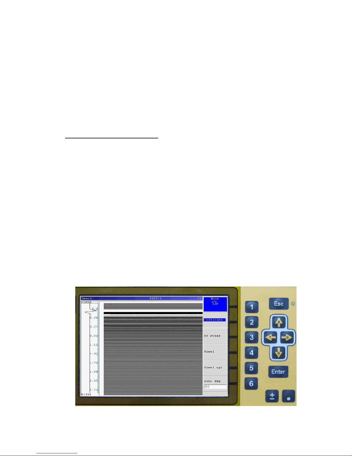
7. Press functional key «6» («Mode», figure 3.4.2). Menu «Mode» (figure 3.4.3) provide for select
the measurements mode of scanning.
• Continues – information about distance doesn’t record.
• By steps – each trace record by pressing «Enter»
• Wheel – If in the device modification stipulated the operation with a moving sensing transducer
(wheel) during work operation in the mode«Wheel», the lines are only recorded through the
distance of a given step (can’t use with BAPP1, BAPP2).
• «Wheel opt.» – It is necessary to check up the established parameters of the used moving
sensing transducer with the help of the menu «Wheel opt» when you use the given mode.
8. Press the functional key «1» («↑__») to return to the menu of parameter measurements settings.
Figure 3.4.3. Mode processing menu
Page 13
14
3.5 The operation of scanning
1. Set the antenna power supply unit on the surface which is to scan and press the functional button
«2» («Record», figure 3.5.1) for the record of a profile.
Figure 3.5.1. Measurements mode menu
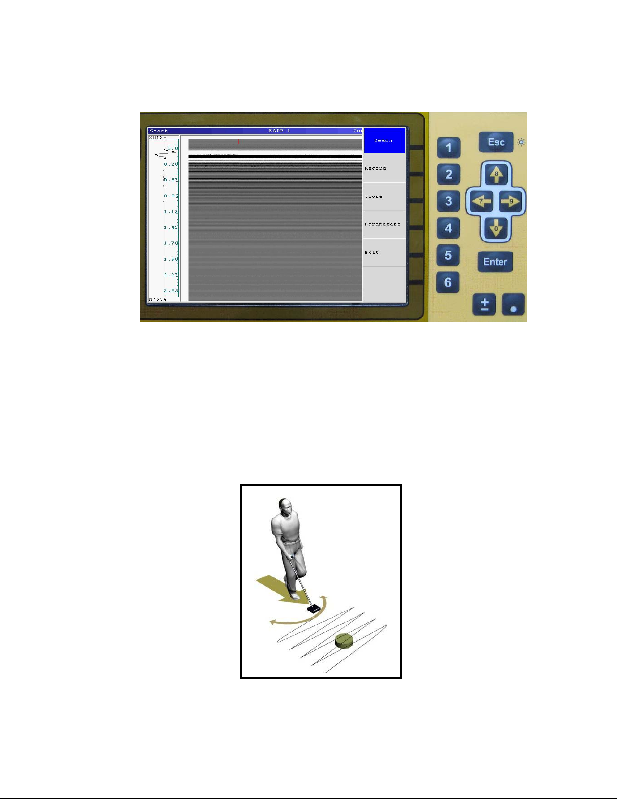
2. Smoothly move the antenna power supply unit on the planned trajectory. The search of the deep
objects is possible to make at the mode, that is similar to the operation with metal detectors and mine
detectors (figure 3.5.2). Antenna unit is possible to take of from a ground surface on a distance 5-10
sm. It doest influence on the detection characteristics. The device in equal intervals will radiate
impulses and accept signals from the moving antenna unit of the device, that are reflected from
inhomogeneities of the scanning environment. The wave picture of the profile (radogramma) will be
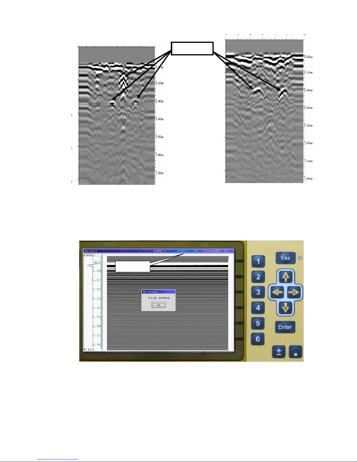
displayed on the BUOI screen while the device will be moving. The reflection of point objects is
displayed on the radogramma as hyperbola (a vertex of hyperbole is to correspond to the nearest point
of objects of the antenna unit), reflection from the objects and layers are represented in tended
horizontal lines (figure 3.5.3).
Figure 3.5.2. The moving trajectory of BAPP in searching of the dug objects
Page 14
15
Figure 3.5.3 The examples of radogramm of detection objects
3. Press button «5» during recording for drawing label. Drawing the label accompany by sound
signal. Program assign labels serial number.
4. Press «Esc» for save file and «Enter» for approval of saving (figure 3.5.4).
Figure 3.5.4. Saving file
5. The «Store» button allows to save a file with information from screen of BUOI.
Local objects
File name
Page 15
16
3.6 Detection of movement
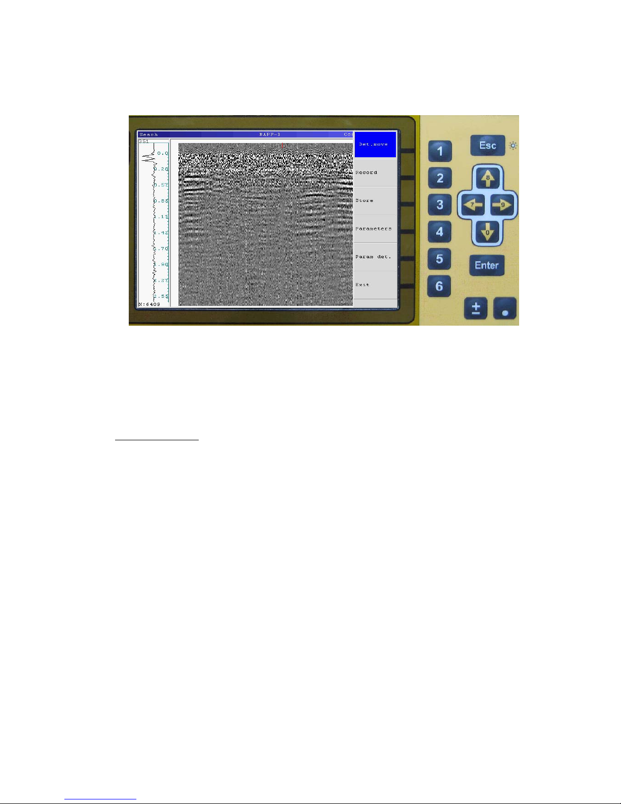
The mode intend for detecting the moving object in real time. Press the functional key «3» in
main menu of BUOI («Det. move», figure 3.4.1) to activate the mode. Select item «Param det»
(button «5», figure 3.6.1).
Figure 3.6.1. The detection of movement mode
Numerical value of parameter "Param det." is to define the quantity of the lines for averaging
and changes by the pointers “↑” и “↓” . If the value «1» is installed, the processing is not performed, if
the value more than 1, the set quantity of the lines is to average and the averaged lines is to subtract
from the again accepted lines. For example, this mode can be useful during the detection of the moving
objects behind the wall and so on.
Recommendation:
Param.det = 50;
Accumulate = 8;
Recording and saving files in this mode make in compliance with section “3.5. The operation
of scanning”.
Page 16
17
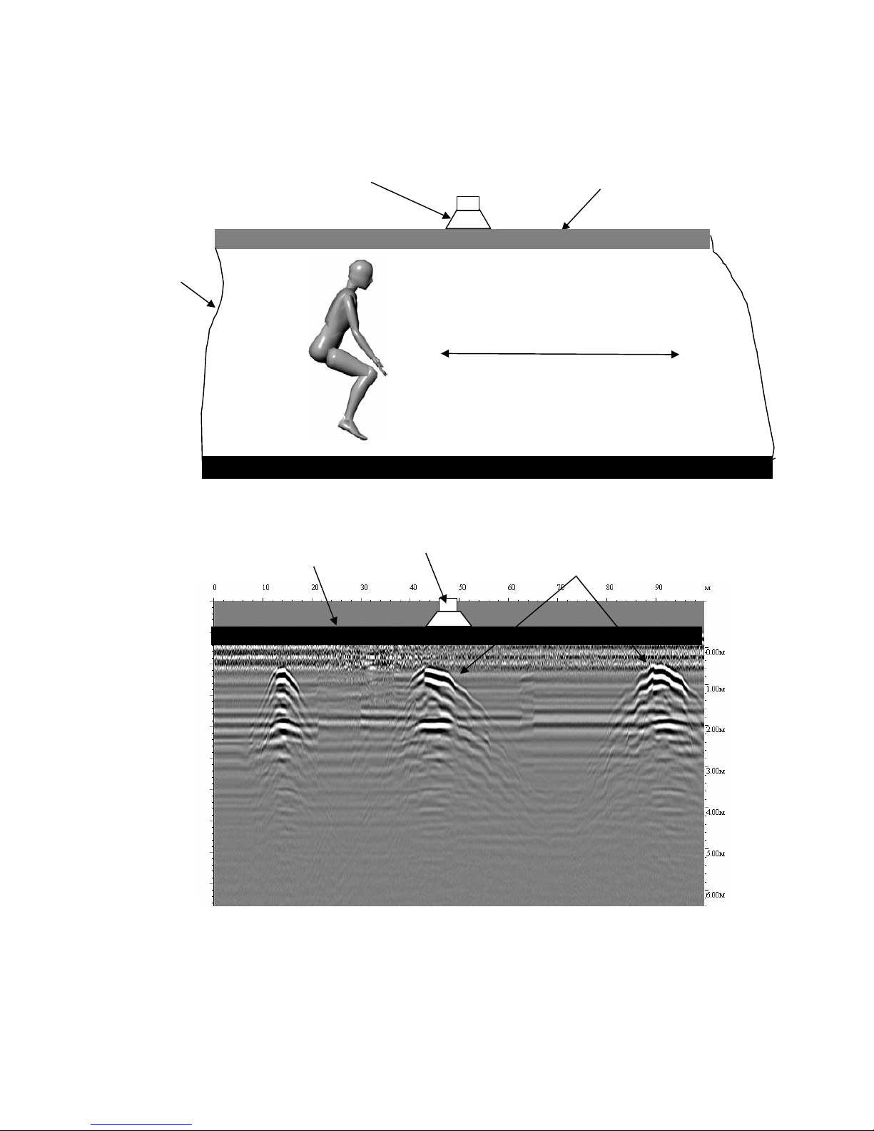
The main condition for the moving objects detection is to fix the antenna unit on the wall
through which the scanning of the adjoining room is made or to fix it on the floor for detection the
objects that are below, on the previous floor-level. On the figure 3.6.2 there is a scheme detection of a
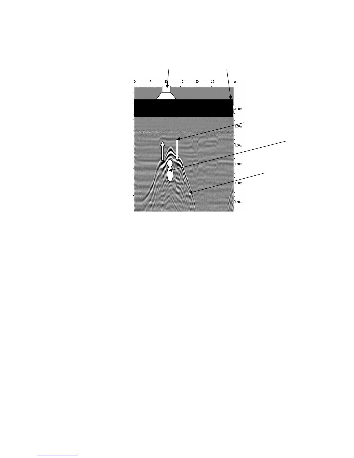
moving person in the concrete tunnel. On the figure 3.6.3 there is a detection radogramm of the
moving person in the concrete tunnel.
Figure 3.6.2. A scheme detection of a moving person in the concrete tunnel.
Figure 3.6.3. Detection radogramm of the moving person in the concrete tunnel
Antenna unit
Iron concrete
blockings
The moving way of a person
Tunnel
Antenna unit
Reflection of a signal
from a person
Iron concrete
blockin
g
s
Page 17
18
For detection the moving objects through the wall it is necessary to fix the antenna unit on the
wall, do not try to keep the unit by hands, it can make the detection of the moving objects complicated.
On the Figure 3.6.4 there is the detection radogramm of the moving animal (dog). The scanning was
made through the brick wall of the adjoining room, the thickness is 40 cm.
Figure.3.6.4. The detection radogramm of the moving animal (dog) that is scanning through the brick
wall
Antenna unit
Brick wall
Dog
Reflected signals
Movement way
Page 18

19
3.7 General recommendations
It is necessary to perform the following recommendations during search work:
1. The device should move along the trajectory planned by operator closely or with distance (up to
0,1 m) from the surface of the scanning environment.
2. The speed of the antenna block moving should be no more than 1 km/s while you are scanning the
complex surfaces on the relief. The antenna unit should contact the scanning surface.
3. For further construction three-dimensional image in the program GeoScan32 write down not less
than 7 parallel profiles (for more details see Users guide of the program GeoScan32).
4. Remove BAPP from the folding handle rod for scanning in the places with difficult access and use
the cable with the 5 meters length, perform the operations by two operators.
5. Press the functional key “Esc” at the final point of a trajectory, thus there will be «Mode Menu of
measurements» (Figure 2.8). Press a function key «3» «Save » to save all the dates on a hard disk of
BUOI. On the BUOI screen will appear the window with the number of a kept file, press twice the
fictional key Enter to confirm the keeping.
Press the functional key «2» for recording the following profile («Profile», Figure 2.8).
To input in the main choice menu of an operation mode press the functional key «5»
(«Output»,Figure. 2.8). The light-emitting diode (LED) indicator on the BAPP case will not flash, it
means that the transmitting unit of the device will be switched on.
3.8 Functioning of “Start-Stop” button.
Start-Stop” button (figure 3.1.3) is for the on-line control of the start and end of the signal
recording, putting marks (tags) during recording and it functions in the following way:
Short-term pressing of Start-Stop” button signals the start of signal recording (“Record” mode
is switched on).
Short-term pressing of Start-Stop” button while signals recording helps to put marks (tags) on
the profile. The marks serve for the additional referencing of the profile to the location.
Long pressing (about 2 sec.) of Start-Stop button while signals recording terminates the profile
recording and stores a profile file to the power supply independent memory unit of BUOI.
3.9 Device Switching off and Disassembling.
To switch off the device press only once the button on the case of PSU (power supply unit) to
switch off the power supply (wherein the LED indicator on PSU goes out).
After switching off SK the device must be disassembled (in the order opposite to assembling
order) and packed in transportation bag according to the scheme of packing.
Page 19
20
3.10 Viewing files
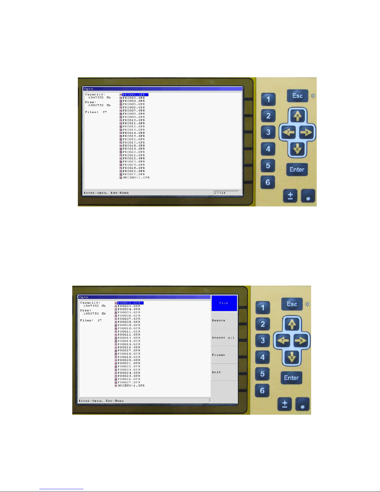
Pressing a“4” functional key in the menu of device operation mode selection («File», figure
3.3.1) select an operation mode “File.”
In opening operation mode menu a list of files of profiles with extension *.GPR stored in a
hard drive of BUOI is displayed. (Figure 3.10.1).
Figure 3.10.1. Menu list of the stored files.
To open a file use “↑” и “↓” keys to chose a required file and press an Enter button. If you
press Esc now, a menu for work with files will appear on the screen (figure 3.10.2), which eanables
either to delete this file or to delete all files, or to format a hard drive of BUOI.
Warning! BUOI hard drive formatting deletes all files on it! Formatting is to be used only for
correcting errors in file system of BUOI.
Figure 3.10.2 Menu of files operation
Page 20
21
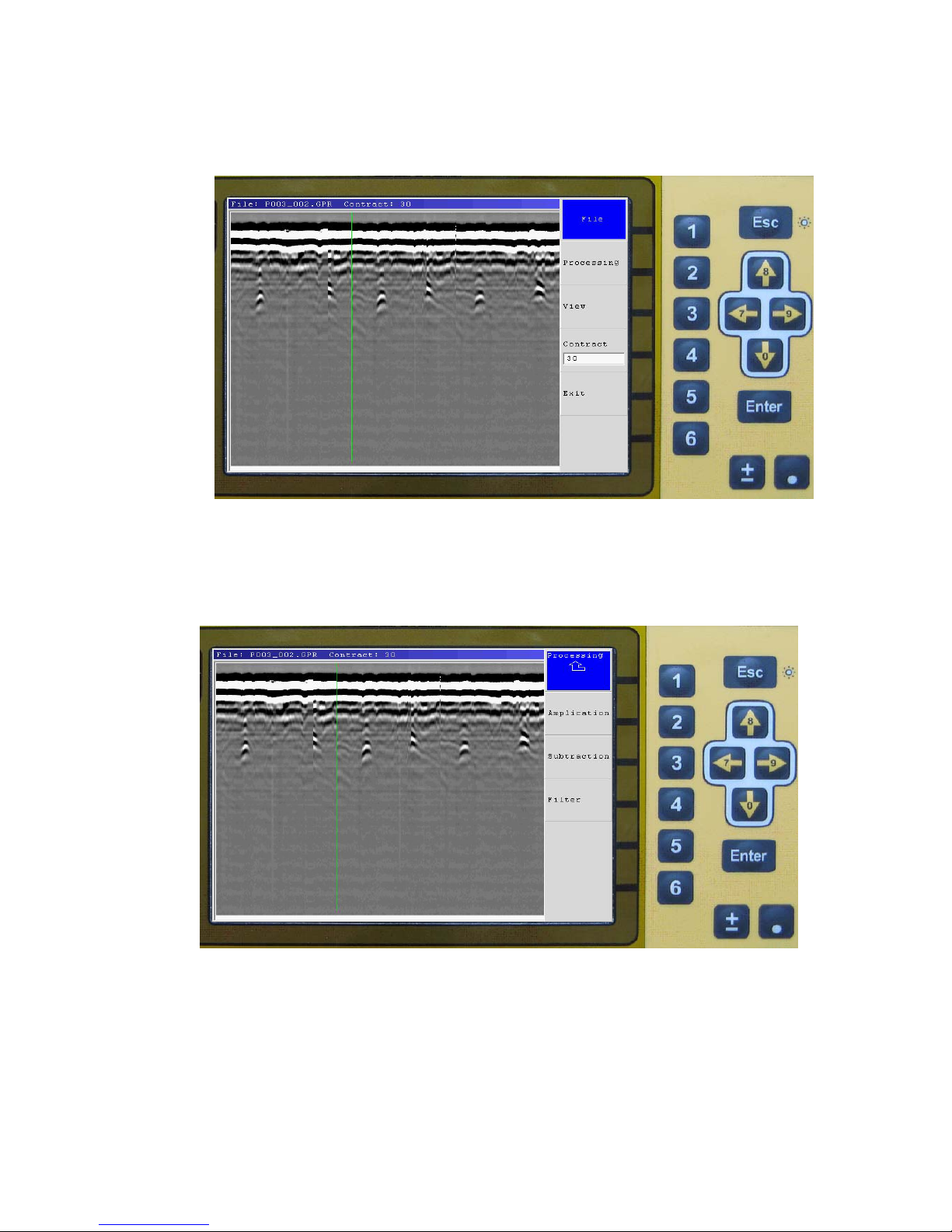
Press the key «Enter» («Open») to open the selected file, the name of the file is displayed at the
left corner of the screen. After the file is opened, press the button “Esc” (figure 3.10.3) the menu of the
processing file are selected, where become accessible the options of the processing «Processing»,
«View» and «Contract» (figure 3.10.4).
Figure 3.10.3. Menu of the fail processing list
Press the functional button «2» (figure 3.10.3) and the options of processing files
«Amplication», «Subtraction», «Filter» become accessible (figure 3.10.4). Assignment and necessity
of application of each kind of processing is represented in User s manual of the program GeoScan32.
Figure 3.10.4. File processing menu
Page 21
22
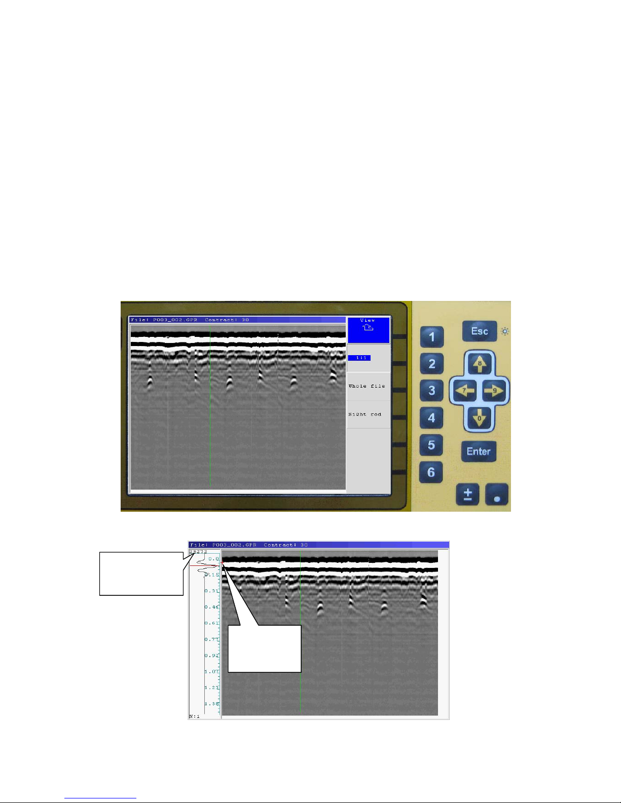
«View» button give an access to a menu for handling with a display of radarogramm on a
screen of BUOI (figure 3.10.5)
Press a “2” functional key («1:1» (figure 3.10.5) and then a Esc key a mode «1:1» is activated.
At that if the file size is less than a screen size, then a radarogramm takes only part of a screen ; if the
file size is more than a screen size, then only that part of a radarogramm that will have space on the
screen will display on a screen of BUOI. If the file size is more than a screen size than the keys «←»
and «→» enable to move a displayed part of the image.
Press a “3” functional key («Whole file»(figure 3.10.5)),and then an Esc key a radarogramm is
scaled that it could have space on a screen of BUOI.
Press a “4” functional key («Sight rod»,(Figure 3.10.5)), and then an Esc key, the oscillogramm
corresponding to a signal of direct transmission and reflected signals (figure 3.10.6) is displayed. Keys
«←» and «→» enable to move the oscillogramm on the file to the left or to the right , and keys «↑» or
«↓» enable to move up or down on the sight rod, while amplitude of the current point is being
displayed in the upper left corner of the sight rod window.
Press a “4” functional key («Contrast», figure 3.10.3) activates a mode of contrast ratio of a
radarogramm and “↑” & “↓” keys install a required value.
Figure 3.10.5. Menu "View"
Figure 3.10.6. The view of sighting
Amplitude of the
present point of
radogramma
The present
point of
radogramma
Page 22
23
3.11 Settings
Press a “4” functional key in a menu of a device operation mode (“Settings”, figure 3.3.1)
select an operation mode “Settings“.
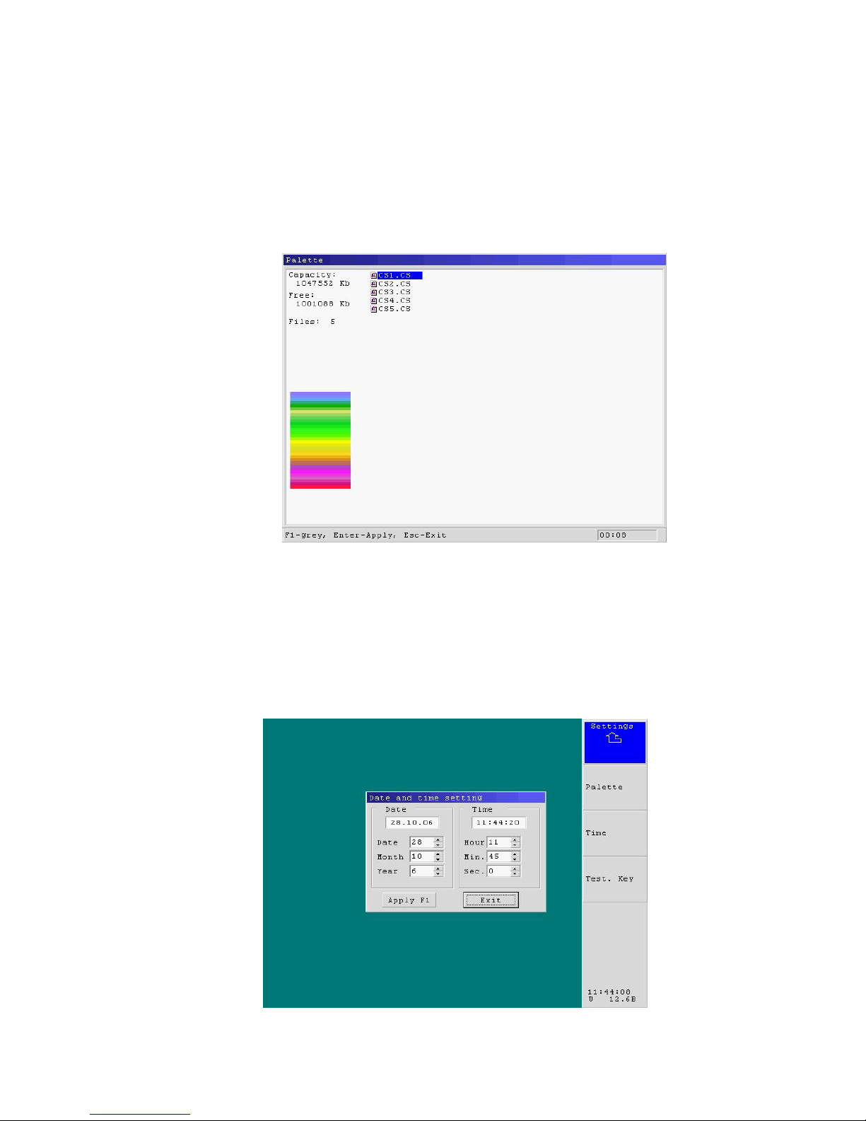
In an open menu of a Settings mode items of “Palette”, “Time”, and “Test. key” are displayed.
3.11.1 Palette
Press a “2” functional key “ Palette” (figure 2.11.1) displays a list of a colors palette files
(palette files can be recorded with the help of a GeoScan 32 program) and a sample of the palette
colors (blue color) for a file selected
Figure 3.11.1. List of colors palette
By “↑” & “↓” keys select a file with a required color palette. Black- and white palette is
selected by a “1” functional key. Press an Enter key enables to activate a selected palette for
representation of profiles.
3.11.2 Time settings
Press a “3” functional key ‘Time” enables to activate a menu of date and time settings (figure
3.11.2).
Figure 3.11.2. Date and time settings
Page 23
24
To set up date and time one should set up date and time in corresponding items from which the
timer will start counting out.
Item selection is made by "←", "→", "↑", "↓"keys.
To change the value of a selected item, press an "Enter" key, thereafter you can change the
value by "↑" или "↓"keys. Termination of a value change is enabled by pressing "Enter".
To change a value of timer counting out, you should chose “Use” key and press an "Enter" key.
A time setting window is closed by pressing an Enter key while an Exit key is selected or by
pressing an Esc key.
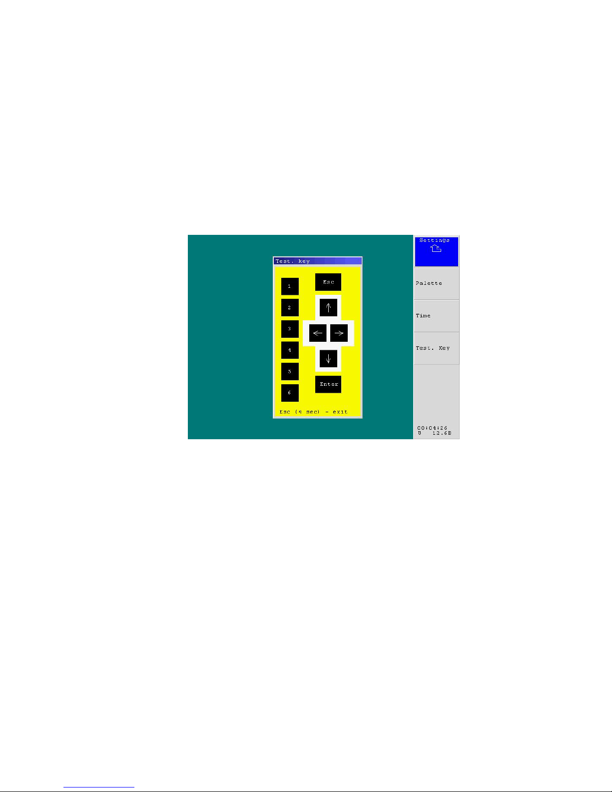
3.11.3 Testing keys
Press a “4” functional key («Тest. Key.») a display for testing operation of a BUOI keyboard
(figure 3.11.3). When the keys are pressed, their view on a screen is colored in a different color. To
enter the Main menu an ESC. Key is held for 4 seconds.
Figure 3.11.3. Testing keys
Page 24
25
4. File Transfer from BUOI into a computer
To transfer profiles which are in BUOI into hard drive of external PC the following steps are to
be fulfilled (the device must be in a working position and switched on):
1. Connect BUOI to an external PC using connecting PC cable (from the accessories) through
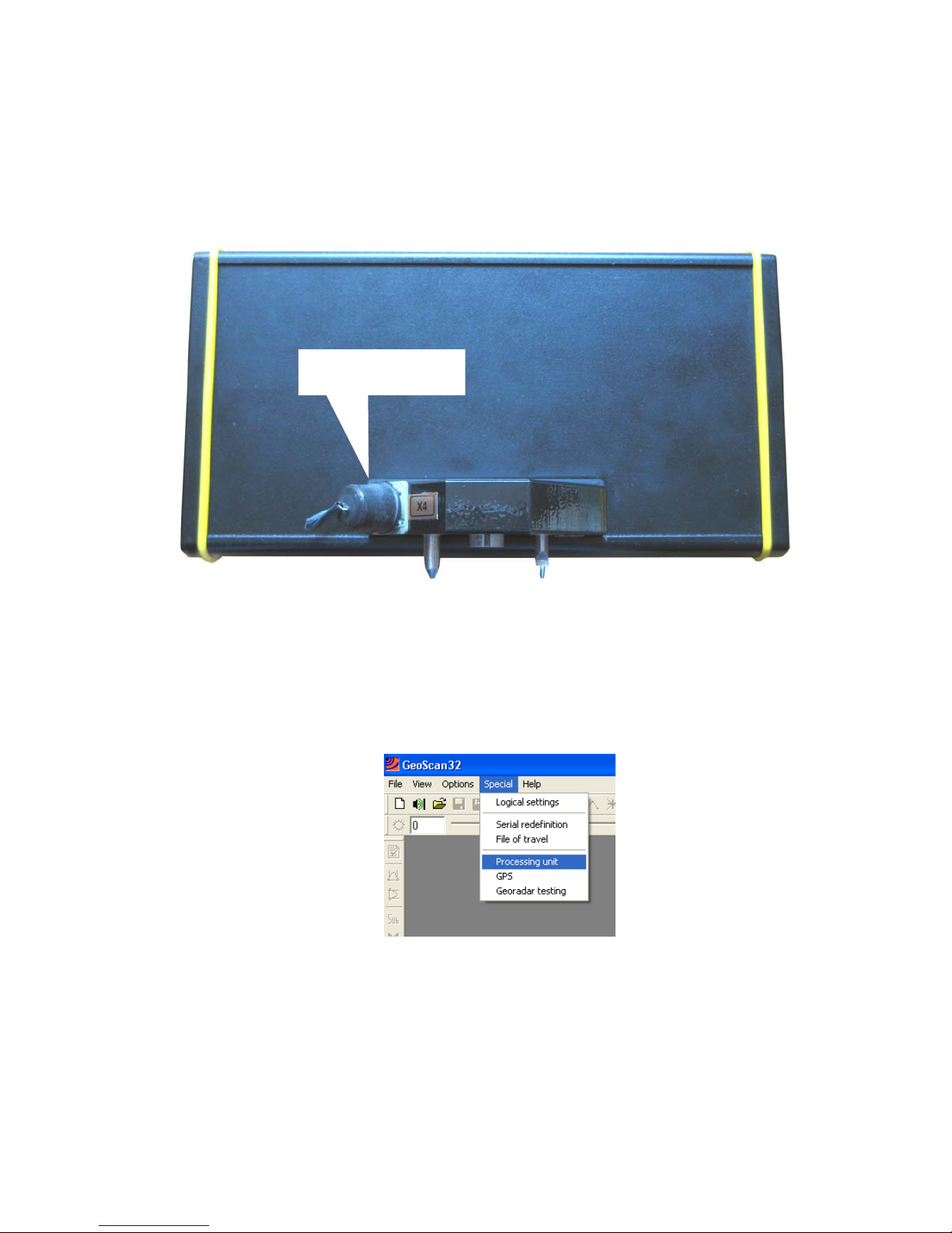
Ethernet port. Input connector of a connecting cable on a case of BUOI is shown in figure 4.1.
Figure 4.1. Input connector linking up BUOI with PC
2. Switch on PC and Search kit OKO-2 (Settings of network adapter and those of a computer Ethernet
port must be the following: IP-Internet protocol address is TCP/IP 10.0.0.100, subnetwork mask is
255.255.255.0, IP-georadar address is 10.0.0.200.).
Warning! After switching on BUOI do not exit a device operation mode selection menu
3. Start up GeoScan32 Program and select a menu item “Special/Processing Unit”
Figure 4.2. Program GeoScan32
Input connector of a
connecting cable
Page 25
26
After activating a menu item “Processing Unit” in GeoScan32 Program window, a window
“Transferring profiles from a Processing Unit” will display.
Figure 4.3. Window “Transferring profiles from a Processing Unit”
( If there is no file displayed in the window, you should disconnect BUOI from a computer,
shut all radarograms in GeoScan32 program window , enter “ Special” menu and click a line “ Logis
Settings”).
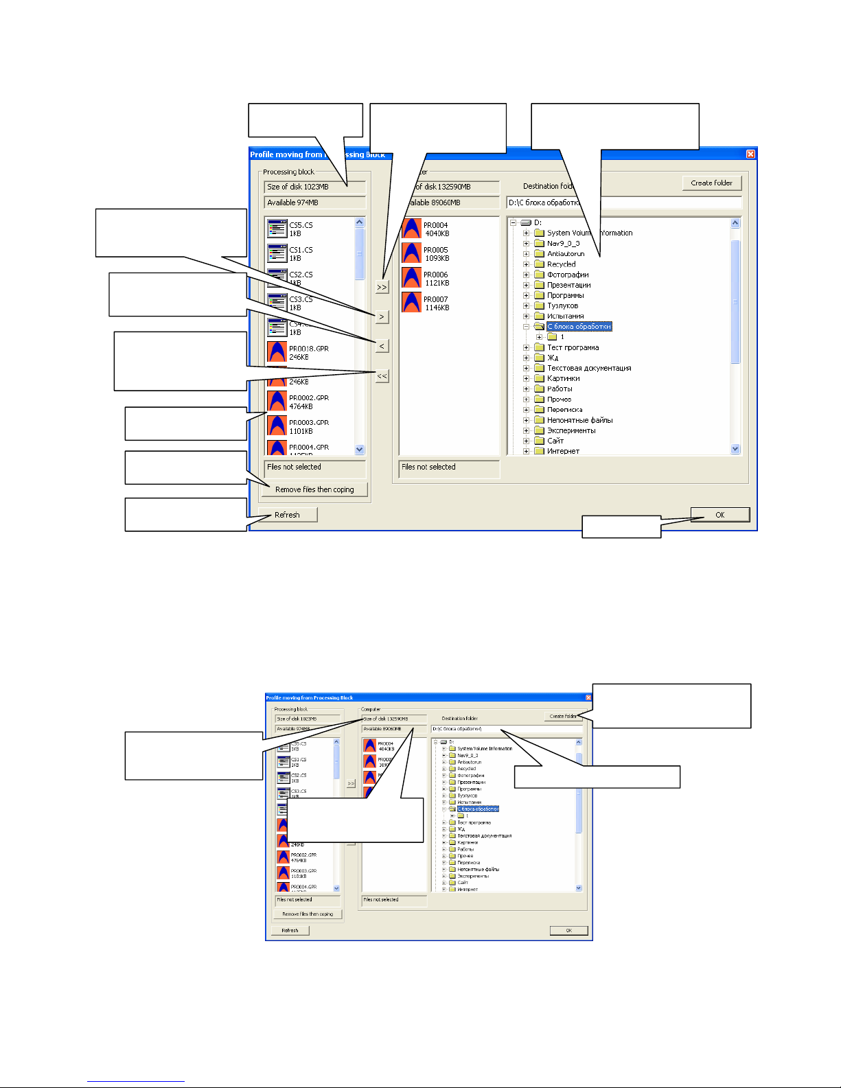
4. Chose a computer directory where all the files from BUOI will be copied (figure 4.4).
Figure 4.4. Window “Transferring profiles from a Processing Unit”
Flash - memory size
of Processin
g
Unit
The list of all files of
the Processin
g
Unit
Copy all the profiles from
the Processing Unit to the
computer
Copy the allocated profiles
from the Processing Unit to
the computer
Copy the allocated profiles
from the computer to the
Copy all the profiles
from the selected folder
of the computer to the
Processing Unit
The election of computer
directory where the files will be
copied from the Processing Unit
To delete files on the
Processin
g
Unit
To update (restore)
the list of files
Close panel
The overall size of a
selected logical hard drive
A size of accessible space
of a selected logical hard
drive
Full path to the selected folder
Create a new folder with name
written in the line below in the
chosen director
y
Page 26
27
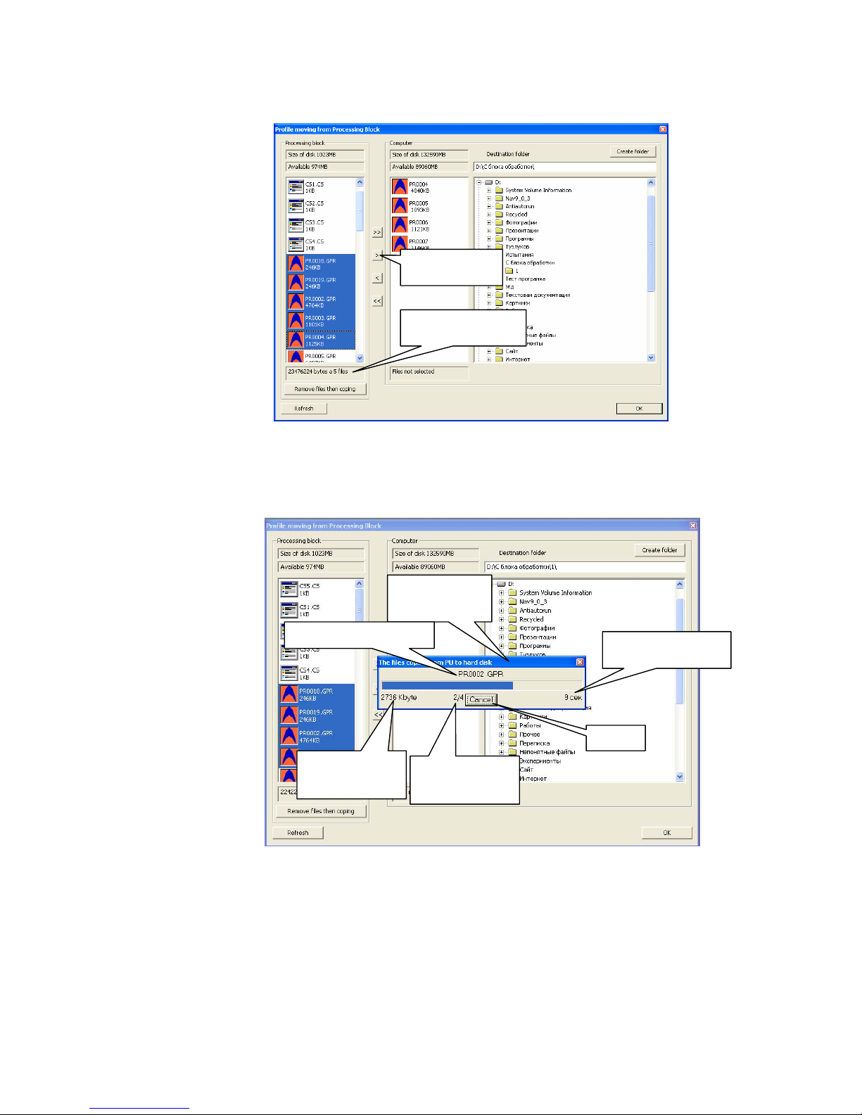
Holding a “Ctrl” key, and clicking the left mouse button select files. To select one file it is
enough to click the left mouse button on the sign of the required file (figure 4.5).
Figure 4.5. Selected files
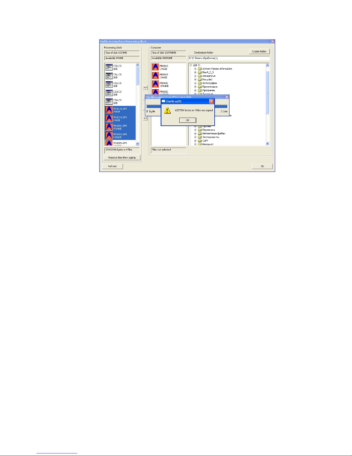
To start copying files press an “OK” key. After pressing “OK” key a window graphic
representation of copying process will display on the screen (figure 4.6).
Figure 4.6. Copying process
Key for coping
the selected files
The size and quantity
of the selected files
A window graphic
representation of
co
pying p
rocess
Name of the copying files:
Prospective time before
and of copying
The quantity which
has remained for
copying of data
The quantity which
has remained for
copying of files
Cancel
Page 27
28
After finishing a copying process a window with a corresponding message will display in the
screen (figure 4.7).
Figure 4.7. Finishing a copying process
After recording files on PC you can start processing them in GeoScan32 program. For details
about processing and analysis of radarogram see User Manual.
5. Operation with SK «Око-2» using a notebook.
SK «Oko-2» presupposes a possibility of standard work using a notebook as an external control
device along with a possibility to use all memory of notebook. You should do as follows:
1. Assemble SK «Oko-2» (see item 3.1 of the present manual);
2. Connect BUOI to a notebook with a connecting cable of PC through Ethernet port. Input connector
of a connecting cable on a case of BUOI is shown in figure 4.1;
3. Pressing the button on a case of Power Unit switch on power supply of a device. At this moment a
LED indicator will start flashing on a case of PU and in a few seconds after automatic testing SK
“Oko-2” and a short time message «ready for work», a device operation mode selection menu will
display on a screen of BUOI and a current voltage of BP too;
4. Switch on a notebook and wait for the loading of operating system;
5. Start up GeoScan32 program;
6. Further work is fulfilled according to a User Manual for GeoScan32 Program.
Page 28

29
6. Requirements on safe operation and electromagnetic
compatibility.
While using the device for the specified purpose (the transmitting unit of the device is switched
on, about which the LED indicator on the casing of BAPP signals), one may not set the antenna units
to the people. Safety of SK «Oko-2» when the standard position of the device is observed (BAPP is
set to the investigated cargo and is moved along or under the surface at the distance of up to 0.1 m
from the surface of the cargo) is confirmed by the conclusion of the sanitary supervision and disease
control of Center for Sanitary and Epidemiological Supervision of CSSS of the Russian Ministry of
Health dated 03.07.2007 г. № 50.99.04.431.П.008785.07.07.
• One may not sink the device or its separate parts into water or any other liquids.
• One should avoid (exclude) heavy blows and mechanical damages in running or transporting
the device.
• The device does not distribute electromagnetic interference (noise) higher than a permissible
noise level.(See Sanitary Certification).
7. Technical maintenance.
7.1 General instructions.
1. During technical maintenance some preventive maintenance is performed to maintain the proper
condition of the device and to provide its normal operation within the service life (8 years).
2. Recommended frequency and types of technical maintenance:
3. External examination – before each running – no damages incompatible with the operation isolation damages, cracks and so on may not be available on the case of the device and connecting
cables;
4. External cleaning – once in three months – decontamination of the device and split connectors
surface;
5. Battery charging PU 3,8/12 – not less than one time in 3 months-including power supply units
included in tools, parts and accessories ZIP-0, working as required.
7.2 Maintenance procedure
During the external examination of the device you should test the fastening BUOI, BP and
BAPP to a folding handle rod, paint–and-lacquer coating condition, lack of chips and cracks on the
parts made of glass-fiber material and plastic, as well as on painted parts.
Battery charging PU 3,8/12 is to be performed at reduced voltage 10.5 V, but not less than once
in 3 months ( including Power Unit(PU) from the accessories ZIP-0).
Page 29

30
Battery charging is performed as follows:
1. Connect a power unit (PU)3,8/12 to a charging unit (CU-2);
2. Switch a power unit.
3. Switch on a charging unit to the socket 220 V 50 herz, observing the necessary measures of
electrical safety;
4. Leave PU3,8/12 in such a condition for 8 – 10 hours.
The process of charging starts automatically after a connecting a charging unit to the electric
mains:
First phase of battery testing comes. This phase lasts about 10seconds while the red LED on the
case of a charging unit is flashing.
After finishing a test phase a process of charging PU 3,8/12 is switched on, which is indicated
by a constantly gleaming. After the end of a charging process a green LED starts to flash, a red LED is
not indicated, and a power unit turns to a mode of maintaining a charged status of the battery (trickle –
charge). A battery is charged but it may be connected to a charging unit for unlimited time.
To preventively discharge the batteries (in order to decrease “memory effect”, hold the button
PRESS for 2 seconds. After the process of discharging the battery, which may last several hours, a
charging process is switched on automatically.
If a red LED goes on flashing after the end of a test phase which lasts 10 seconds, and does not
turn to a steady shining light, indicating a charging process that signifies that there is a malfunction of
a battery and that the latter should be replaced by another one (from the accessories ZIP-0).
8. Routine Repair.
Routine repair is performed by a company manufacturing. To perform a routine repair a
defective unit of the device is sent to a company manufacturing with a detailed description of the
detected malfunctions. If the defects of the unit cannot be pin – pointed, the whole device is sent for
repair.
9. Storage
Storage conditions of a device are to meet the requirements of GOST В9.003-80 and GOST
15150-69. A device is to be stored in storage buildings in the packing of a company manufacturing
(not more than 5 packing sets may be in a pile) at the temperature of a surrounding air from +100 C up
to +30°С and humidity up to 80% at temperature of 25°С. O. A group of storage conditions – 1(А).
There must not be any vapor of acids or alkali, aggressive, gases and other hazardous
admixtures, causing a corrosion.
Storage time of a device before commencement of operation is not less than 5 years (without
accumulator unit / rechargeable battery).
Page 30

31
10. Transportation
Device transportation is performed by any transport to any distance in packing of a company
manufacturing in observing the following regulations:
1. SK Oko-2 transportation must be performed in a closed transport: railway cars, containers,
closed vehicles, holds without any marks of cement or chemicals transportation and so on. When
transported by air the apparatus must be placed in a sealed compartment.
2. The temperature of a surrounding air during transportation must be from -30°С up to + 50°С
an the pressure from 84 до 106,7 кPа (630-800 mm of a mecury column).
3. Placing and securing of a box with a device on transport facilities must provide a steady
position during transportation, lack of bias(displacement) and strikes and impacts of the devices by
each other
4. Requirements of signs indicated on packing must be observed in loading and unloading.
11. Utilization
Accumulator batteries Ni-Mh 3,8/12В from the unit (PU) БП 3,8/12 are subject to utilization
approved by RF State Technical Committee.
Page 31
32
Page 32
33
Page 33
34
 Loading...